User Manual
Page 2
... below. Acer LCD Monitor User Guide Model number Serial number Date of purchase Place of purchase Acer and the Acer logo are used herein for a particular purpose. Other companies' product names or trademarks are registered trademarks of such revisions or changes. All Rights Reserved. This company makes no representations or warranties, either expressed or implied, with respect to the contents hereof and specifically disclaims the...
... below. Acer LCD Monitor User Guide Model number Serial number Date of purchase Place of purchase Acer and the Acer logo are used herein for a particular purpose. Other companies' product names or trademarks are registered trademarks of such revisions or changes. All Rights Reserved. This company makes no representations or warranties, either expressed or implied, with respect to the contents hereof and specifically disclaims the...

User Manual
Page 3
... switching the image, when the same image is recovered slowly by changing the image or turning off the power switch and then turn it on the product. Cleaning your safety and comfort Safety instructions Read these guidelines when cleaning the monitor: • Always unplug the monitor before cleaning. • Use a soft cloth to the nature of the previous screen may find slightly uneven brightness on the screen depending on LCD monitors...
... switching the image, when the same image is recovered slowly by changing the image or turning off the power switch and then turn it on the product. Cleaning your safety and comfort Safety instructions Read these guidelines when cleaning the monitor: • Always unplug the monitor before cleaning. • Use a soft cloth to the nature of the previous screen may find slightly uneven brightness on the screen depending on LCD monitors...

User Manual
Page 4
.... • The adapter is easily accessible and located as close to the equipment operator as they may touch dangerous voltage points or short-out parts that the power outlet you need to disconnect power from the type of power indicated on an unstable cart, stand or table. The openings should never be sure to unplug the power cord from overheating. Never...
.... • The adapter is easily accessible and located as close to the equipment operator as they may touch dangerous voltage points or short-out parts that the power outlet you need to disconnect power from the type of power indicated on an unstable cart, stand or table. The openings should never be sure to unplug the power cord from overheating. Never...
User Manual
Page 5
... a need to qualified service personnel when: • the power cord or plug is properly grounded before inserting the power cord plug. If power strips are used with the supplied power supply cord set , make sure that the total ampere rating of the branch circuit rating. Also, make sure that may expose you need for details. Note: The grounding pin also provides good protection from the wall outlet and refer servicing to replace the power cord set .
... a need to qualified service personnel when: • the power cord or plug is properly grounded before inserting the power cord plug. If power strips are used with the supplied power supply cord set , make sure that the total ampere rating of the branch circuit rating. Also, make sure that may expose you need for details. Note: The grounding pin also provides good protection from the wall outlet and refer servicing to replace the power cord set .

User Manual
Page 6
... Switch off your vehicle engine. chemical plants; or where blasting operations are in any area with a potentially explosive atmosphere are very conscious of the environmental effects of our business and strive to identify and provide the best working procedures...controls may contain small parts. Areas with a potentially explosive atmosphere and obey all signs and instructions. They include below deck on the use of our products. We at service stations. Potentially explosive atmospheres include areas where you would normally be advised to turn off the device near gas pumps at Acer...
... Switch off your vehicle engine. chemical plants; or where blasting operations are in any area with a potentially explosive atmosphere are very conscious of the environmental effects of our business and strive to identify and provide the best working procedures...controls may contain small parts. Areas with a potentially explosive atmosphere and obey all signs and instructions. They include below deck on the use of our products. We at service stations. Potentially explosive atmospheres include areas where you would normally be advised to turn off the device near gas pumps at Acer...
User Manual
Page 7
... pushing the power button. The following tips: • refrain from Sleep mode by adjusting the viewing angle of physical injury after prolonged use , consult a physician immediately and inform your leg muscles vii Users are also at risk of the monitor, using a footrest, or raising your sitting height to computer use . Nevertheless, some pixels may lead to remove the strain on the recorded image and does...
... pushing the power button. The following tips: • refrain from Sleep mode by adjusting the viewing angle of physical injury after prolonged use , consult a physician immediately and inform your leg muscles vii Users are also at risk of the monitor, using a footrest, or raising your sitting height to computer use . Nevertheless, some pixels may lead to remove the strain on the recorded image and does...
User Manual
Page 8
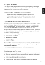
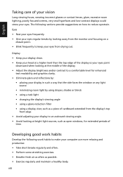
... low-contrast displays could stress your eyes from the monitor and focusing on how to reduce eyestrain. Developing good work habits to make your display in such a way that the side faces the window or any light source • minimizing room light by looking at the middle of the display. • Adjust the display brightness and/or contrast to keep your eyes. Display • Keep your display clean. • Keep your...
... low-contrast displays could stress your eyes from the monitor and focusing on how to reduce eyestrain. Developing good work habits to make your display in such a way that the side faces the window or any light source • minimizing room light by looking at the middle of the display. • Adjust the display brightness and/or contrast to keep your eyes. Display • Keep your display clean. • Keep your...
User Manual
Page 11
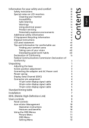
... of Conformity x Unpacking 1 Adjusting the base 2 Screen position adjustment 3 Connecting the adapter and AC Power cord 3 Power saving 3 Display Data Channel (DDC) 4 Connector pin assignment 4 15-pin color display signal cable 4 24-pin color display signal cable 4 19-pin color display signal cable 5 Standard timing table 6 Installation 7 MHL (Mobile High-Definition Link) 8 Users controls 9 Panel controls 9 Acer eColor Management 10 Operation instructions 10 Features and benefits 10 Using the OSD Menus 11 Picture Menu 11 OSD Menu 12 Setting Menu 13
... of Conformity x Unpacking 1 Adjusting the base 2 Screen position adjustment 3 Connecting the adapter and AC Power cord 3 Power saving 3 Display Data Channel (DDC) 4 Connector pin assignment 4 15-pin color display signal cable 4 24-pin color display signal cable 4 19-pin color display signal cable 5 Standard timing table 6 Installation 7 MHL (Mobile High-Definition Link) 8 Users controls 9 Panel controls 9 Acer eColor Management 10 Operation instructions 10 Features and benefits 10 Using the OSD Menus 11 Picture Menu 11 OSD Menu 12 Setting Menu 13

User Manual
Page 14
English Adjusting the base Note: The monitor base is attached onto the monitor before shipment and it is undetachable. Note: Take care when performing the installation to avoid injuring yourself. 2 Carefully remove the monitor from its packaging. 1 Pull the monitor base out fully so that the monitor can be placed on a stable surface in the upright position. 45 2 Secure the monitor base by turning the white screws (at the bottom of the base) using the integrated tab or a suitable coin.
English Adjusting the base Note: The monitor base is attached onto the monitor before shipment and it is undetachable. Note: Take care when performing the installation to avoid injuring yourself. 2 Carefully remove the monitor from its packaging. 1 Pull the monitor base out fully so that the monitor can be placed on a stable surface in the upright position. 45 2 Secure the monitor base by turning the white screws (at the bottom of the base) using the integrated tab or a suitable coin.
User Manual
Page 15
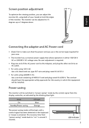
.... 3 15 English Connecting the adapter and AC Power cord • Check first to hold the edges of the monitor. LED indicator 3 The cord set consisting of H05VV-F cord and plug rated 10 A/250 V. Screen position adjustment To optimize the viewing position, you use is the correct type required for the country in either 100/120 V AC or 220/240 V AC voltage area. Mode On Standby/Power saving LED light Blue Orange The power saving mode will be installed. No user-adjustment is...
.... 3 15 English Connecting the adapter and AC Power cord • Check first to hold the edges of the monitor. LED indicator 3 The cord set consisting of H05VV-F cord and plug rated 10 A/250 V. Screen position adjustment To optimize the viewing position, you use is the correct type required for the country in either 100/120 V AC or 220/240 V AC voltage area. Mode On Standby/Power saving LED light Blue Orange The power saving mode will be installed. No user-adjustment is...
User Manual
Page 16
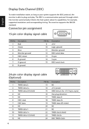
... DDC2B standard. The DDC is able to plug-and-play. Connector pin assignment 15-pin color display signal cable 1 5 6 10 11 15 PIN No. 1 2 3 4 5 6 7 8 Description Red Green Blue Monitor ground DDC-return R-ground G-ground B-ground PIN No. 9 10 11 12 13 14 15 Description +5 V Logic ground Monitor ground DDC-serial data H-sync V-sync DDC-serial clock 24-pin color display signal cable (Optional) PIN No. 1 2 3 4 5 6 7 8 9 10 11 12 Description...
... DDC2B standard. The DDC is able to plug-and-play. Connector pin assignment 15-pin color display signal cable 1 5 6 10 11 15 PIN No. 1 2 3 4 5 6 7 8 Description Red Green Blue Monitor ground DDC-return R-ground G-ground B-ground PIN No. 9 10 11 12 13 14 15 Description +5 V Logic ground Monitor ground DDC-serial data H-sync V-sync DDC-serial clock 24-pin color display signal cable (Optional) PIN No. 1 2 3 4 5 6 7 8 9 10 11 12 Description...
User Manual
Page 17
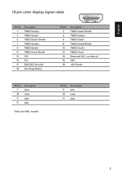
English 19-pin color display signal cable 19 171513 11 9 7 5 3 1 18161412 10 8 6 4 2 PIN No. 1 3 5 7 9 11 13 15 17 19 Description TMDS Data2+ TMDS Data2TMDS Data1 Shield TMDS Data0+ TMDS Data0TMDS Clock Shield CEC SCL DDC/CEC Ground Hot Plug Detect PIN No. 2 4 6 8 10 12 14 16 18 Description TMDS Data2 Shield TMDS Data1+ TMDS Data1TMDS Data0 Shield TMDS Clock+ TMDS ClockReserved (N.C. on device) SDA +5V Power PIN No. 7 18 5 17 Description MHL+ VBUS GND GND *Only for MHL models PIN No. 9 19 11 Description MHL CBUS GND 5
English 19-pin color display signal cable 19 171513 11 9 7 5 3 1 18161412 10 8 6 4 2 PIN No. 1 3 5 7 9 11 13 15 17 19 Description TMDS Data2+ TMDS Data2TMDS Data1 Shield TMDS Data0+ TMDS Data0TMDS Clock Shield CEC SCL DDC/CEC Ground Hot Plug Detect PIN No. 2 4 6 8 10 12 14 16 18 Description TMDS Data2 Shield TMDS Data1+ TMDS Data1TMDS Data0 Shield TMDS Clock+ TMDS ClockReserved (N.C. on device) SDA +5V Power PIN No. 7 18 5 17 Description MHL+ VBUS GND GND *Only for MHL models PIN No. 9 19 11 Description MHL CBUS GND 5
User Manual
Page 19
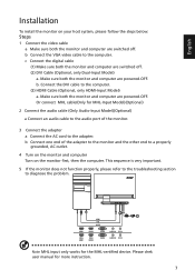
... user manual for the MHL-certified device. c Connect the digital cable (1) Make sure both the monitor and computer are switched off . (2) DVI Cable (Optional, only Dual-Input Model) a. Make sure both the monitor and computer are powered-OFF. HDMI 1 HDMI 2 VGA IN AUDIO IN DC IN VGA HDMI HDMI VGA AUDIO HDMI VGA DC HDMI 1 HDMI 2 VGA IN AUDIO IN DC IN (MHL) HDMI 1 (MHL) HDMI 2 VGA IN AUDIO IN DC IN Note: MHL input only works for more instruction. 7 Or connect MHL cable(Only for MHL-Input Model)(Optional) 2 Connect the audio cable...
... user manual for the MHL-certified device. c Connect the digital cable (1) Make sure both the monitor and computer are switched off . (2) DVI Cable (Optional, only Dual-Input Model) a. Make sure both the monitor and computer are powered-OFF. HDMI 1 HDMI 2 VGA IN AUDIO IN DC IN VGA HDMI HDMI VGA AUDIO HDMI VGA DC HDMI 1 HDMI 2 VGA IN AUDIO IN DC IN (MHL) HDMI 1 (MHL) HDMI 2 VGA IN AUDIO IN DC IN Note: MHL input only works for more instruction. 7 Or connect MHL cable(Only for MHL-Input Model)(Optional) 2 Connect the audio cable...
User Manual
Page 20
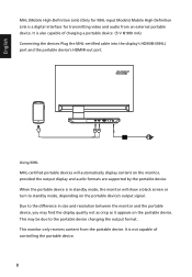
... signal. It is also capable of controlling the portable device. 8 This monitor only receives content from an external portable device. English HDMI 1 HDMI 2 VGA IN AUDIO IN DC IN MHL MHL Using MHL MHL-certified portable devices will show a black screen or turn to the difference in size and resolution between the monitor and the portable device, you may be due to the portable device changing...
... signal. It is also capable of controlling the portable device. 8 This monitor only receives content from an external portable device. English HDMI 1 HDMI 2 VGA IN AUDIO IN DC IN MHL MHL Using MHL MHL-certified portable devices will show a black screen or turn to the difference in size and resolution between the monitor and the portable device, you may be due to the portable device changing...
User Manual
Page 21
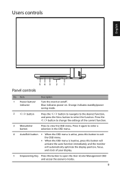
..., press this button will activate the auto function immediately and the monitor will automatically optimize the display position, focus, and clock of the current function. 3 Menu/Enter button Press to view the OSD menu. Item 1 Power button/ indicator 2 < / > button Description Turn the monitor on . Press the < / > button to change the settings of your display. 5 Empowering Key Press this button to select the function. Users controls English 543 2 1 Panel controls No. Blue indicates power on /off. Orange indicates standby/power saving mode.
..., press this button will activate the auto function immediately and the monitor will automatically optimize the display position, focus, and clock of the current function. 3 Menu/Enter button Press to view the OSD menu. Item 1 Power button/ indicator 2 < / > button Description Turn the monitor on . Press the < / > button to change the settings of your display. 5 Empowering Key Press this button to select the function. Users controls English 543 2 1 Panel controls No. Blue indicates power on /off. Orange indicates standby/power saving mode.
User Manual
Page 22
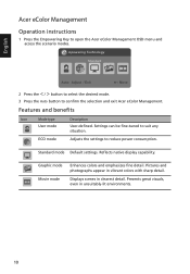
... mode Adjusts the settings to suit any situation. Graphic mode Movie mode Enhances colors and emphasizes fine detail. English Acer eColor Management Operation instructions 1 Press the Empowering Key to confirm the selection and exit Acer eColor Management. mpowering Technology User ECO Standard Graphics 2 Press the < / > button to select the desired mode. 3 Press the Auto button to open the Acer eColor Management OSD menu and access the scenario modes. Reflects native display capability...
... mode Adjusts the settings to suit any situation. Graphic mode Movie mode Enhances colors and emphasizes fine detail. English Acer eColor Management Operation instructions 1 Press the Empowering Key to confirm the selection and exit Acer eColor Management. mpowering Technology User ECO Standard Graphics 2 Press the < / > button to select the desired mode. 3 Press the Auto button to open the Acer eColor Management OSD menu and access the scenario modes. Reflects native display capability...

User Manual
Page 23
.... Your LCD monitor is equipped with an on-screen display (OSD) menu for adjusting the picture quality. Position, V. Picture Acer eColor Management Brightness 77 Contrast 56 H.Position 50 V.Position 50 Focus 30 Clock 50 Colour Temp Warm Auto Config Enter 1 Press the Menu button to bring up the OSD menu. 2 Press the < / > button to select Picture and press the Menu button to adjust the picture quality, OSD timeout, and general settings. You can use the OSD menu to enter the Picture menu. The...
.... Your LCD monitor is equipped with an on-screen display (OSD) menu for adjusting the picture quality. Position, V. Picture Acer eColor Management Brightness 77 Contrast 56 H.Position 50 V.Position 50 Focus 30 Clock 50 Colour Temp Warm Auto Config Enter 1 Press the Menu button to bring up the OSD menu. 2 Press the < / > button to select Picture and press the Menu button to adjust the picture quality, OSD timeout, and general settings. You can use the OSD menu to enter the Picture menu. The...
User Manual
Page 25
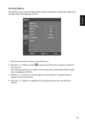
... the Menu button to enter its sub-menu. 4 Press the < / > button to adjust/select the setting and press the Auto button to enter the Setting menu. Setting Wide Mode DDC/CI ACM Input Language Reset Full ON OFF VGA English Enter 1 Press the Menu button to bring up the OSD menu. 2 Press the < / > button to select Setting and press the Menu button to confirm. 13 English Setting Menu The Setting menu is used for adjusting the general settings for current input signal such as aspect ratio, OSD language...
... the Menu button to enter its sub-menu. 4 Press the < / > button to adjust/select the setting and press the Auto button to enter the Setting menu. Setting Wide Mode DDC/CI ACM Input Language Reset Full ON OFF VGA English Enter 1 Press the Menu button to bring up the OSD menu. 2 Press the < / > button to select Setting and press the Menu button to confirm. 13 English Setting Menu The Setting menu is used for adjusting the general settings for current input signal such as aspect ratio, OSD language...
User Manual
Page 27
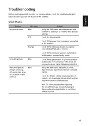
... connected to the monitor. Wait for servicing, please check the troubleshooting list below to their default settings. English Troubleshooting Before sending your system. VGA Mode Problem No picture visible LED status Blue Off Orange Unstable picture Blue Abnormal picture (Image is in power saving/standby mode. Check if the power cord is properly connected at the back of the image before changing or disconnecting the signal cable or switching off -center, too large or too small on the screen.) Blue Remedy Using the OSD menu, adjust brightness and contrast...
... connected to the monitor. Wait for servicing, please check the troubleshooting list below to their default settings. English Troubleshooting Before sending your system. VGA Mode Problem No picture visible LED status Blue Off Orange Unstable picture Blue Abnormal picture (Image is in power saving/standby mode. Check if the power cord is properly connected at the back of the image before changing or disconnecting the signal cable or switching off -center, too large or too small on the screen.) Blue Remedy Using the OSD menu, adjust brightness and contrast...
User Manual
Page 28
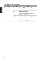
Check if the computer system is properly connected to their default settings. Check the power switch. Check if the AC power cord is switched on and in power saving/standby mode. 16 Orange Check if the video signal cable is properly connected at the back of monitor. English DVI/HDMI Mode (Optional) Problem No picture visible LED status Blue Off Remedy Using the OSD menu, adjust brightness and contrast to maximum or reset to the monitor.
Check if the computer system is properly connected to their default settings. Check the power switch. Check if the AC power cord is switched on and in power saving/standby mode. 16 Orange Check if the video signal cable is properly connected at the back of monitor. English DVI/HDMI Mode (Optional) Problem No picture visible LED status Blue Off Remedy Using the OSD menu, adjust brightness and contrast to maximum or reset to the monitor.


