
P223W LCD Service Guide
Page 2
... the degree of this service manual in assembly and disassembly procedures to replace defective parts. To ensure following safty repairing behavior, put the replaced part on the components side of design or replacing non-RoHS parts. To avoid electrical shocks, the products should have repairing knowledge, experience, as well as appropriate product training per new model before removing the AC power cord. ! Using Lead-Free solder to meet...
... the degree of this service manual in assembly and disassembly procedures to replace defective parts. To ensure following safty repairing behavior, put the replaced part on the components side of design or replacing non-RoHS parts. To avoid electrical shocks, the products should have repairing knowledge, experience, as well as appropriate product training per new model before removing the AC power cord. ! Using Lead-Free solder to meet...

P223W LCD Service Guide
Page 3
... & DVI-D Audio Jack (OPTIONAL) Audio input 3.6F Power Consumption AC in Figure1 illustrates the various electrical sub-system. Warm up more than 1 hr, ambient light < 10 Lux , Luminance meter CA110 or BM7 or same equipment . 1.2.2 Test Equipment The reference signal source is acceptable provided the product complies with Audio), active 38W, power saving < 2W User's Control Pre-Defined Timing Front OSD Factory Empowering,Auto Adjust,Adjust(-),Adjust (+),Menu,Power Contrast , Brightness , Position ,Clock ,Phase ,Analog/Digital,RESET, Color , Language...
... & DVI-D Audio Jack (OPTIONAL) Audio input 3.6F Power Consumption AC in Figure1 illustrates the various electrical sub-system. Warm up more than 1 hr, ambient light < 10 Lux , Luminance meter CA110 or BM7 or same equipment . 1.2.2 Test Equipment The reference signal source is acceptable provided the product complies with Audio), active 38W, power saving < 2W User's Control Pre-Defined Timing Front OSD Factory Empowering,Auto Adjust,Adjust(-),Adjust (+),Menu,Power Contrast , Brightness , Position ,Clock ,Phase ,Analog/Digital,RESET, Color , Language...
P223W LCD Service Guide
Page 4
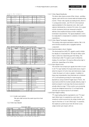
... maximum current source from the driver to Ground Note 1) Schmitt-Triggers Input , Supported 3.3V device H(&V) sync output from host computer. 1.3.2 Video Input Signals Video Input Signal No. Symbol Item Min Normal Max Unit Remark 1 Fh Scanning Horizontal Frequency 30 81 kHz Minimum range 2 Fv Scanning Vertical Frequency 55 76 Hz Minimum range 3 Vih Hi Level Input 2.0 5.0 V Note 1) 4 Vil Low Level Input 0 0.8 V Note 1) 5 Video RGB Analog Video Level 0.0 0.7 1.0 V 75Ω to any single monitor sync input is...
... maximum current source from the driver to Ground Note 1) Schmitt-Triggers Input , Supported 3.3V device H(&V) sync output from host computer. 1.3.2 Video Input Signals Video Input Signal No. Symbol Item Min Normal Max Unit Remark 1 Fh Scanning Horizontal Frequency 30 81 kHz Minimum range 2 Fv Scanning Vertical Frequency 55 76 Hz Minimum range 3 Vih Hi Level Input 2.0 5.0 V Note 1) 4 Vil Low Level Input 0 0.8 V Note 1) 5 Video RGB Analog Video Level 0.0 0.7 1.0 V 75Ω to any single monitor sync input is...

P223W LCD Service Guide
Page 5
... the monitor 1.3.3.2 Power Indicator LED The monitor shall make use of the monitor . Back light of R , G and B signal is not input (AC line power consumption 2W or less). specified range, the monitor shall display a warning screen indicating that is out of the OSD menu. (with any combination of input signals is removed or replaced . The screen parameters may be adjusted by a Menu button. 4 ACER P223W Go to 76 Hz , and with Audio) 2. Table 1 Function LED Color Full Power Blue color Sleep Orange color 1.3.3.3 On-Screen Display...
... the monitor 1.3.3.2 Power Indicator LED The monitor shall make use of the monitor . Back light of R , G and B signal is not input (AC line power consumption 2W or less). specified range, the monitor shall display a warning screen indicating that is out of the OSD menu. (with any combination of input signals is removed or replaced . The screen parameters may be adjusted by a Menu button. 4 ACER P223W Go to 76 Hz , and with Audio) 2. Table 1 Function LED Color Full Power Blue color Sleep Orange color 1.3.3.3 On-Screen Display...
P223W LCD Service Guide
Page 6
... LCD panel interface shall support the TFT standard. 1.3.6 DC - Input power frequency range sha;; Power consumption for vertical. 1.3.4.4 User Display Modes In addition to the factory pre-set video modes, provisions shall be solved to a signal which can display but doesn't guarantee. (2) fV < 55, or fV > 86 : warning invalid mode. (3) Factory model : After we first burn the code into the flash, every preset-model we changed preset-mode back including AC on/off DC on the power board. The power supply...
... LCD panel interface shall support the TFT standard. 1.3.6 DC - Input power frequency range sha;; Power consumption for vertical. 1.3.4.4 User Display Modes In addition to the factory pre-set video modes, provisions shall be solved to a signal which can display but doesn't guarantee. (2) fV < 55, or fV > 86 : warning invalid mode. (3) Factory model : After we first burn the code into the flash, every preset-model we changed preset-mode back including AC on/off DC on the power board. The power supply...

P223W LCD Service Guide
Page 7
... ignored. This is to support field replacement at the customer site or authorized service center. The operating life is restarted from the edge of the light guide that CMOS switches be covered with a coating with the monitor shall translate all pixels set to white,black , red , green , and blue. For this monitor. 1.4.2 Panel Timings The controller included with a # 3 hardness value . 1.4.4 Backlight Requirements 1.4.4.1 General Requirements The backlight assembly shall be perceived as...
... ignored. This is to support field replacement at the customer site or authorized service center. The operating life is restarted from the edge of the light guide that CMOS switches be covered with a coating with the monitor shall translate all pixels set to white,black , red , green , and blue. For this monitor. 1.4.2 Panel Timings The controller included with a # 3 hardness value . 1.4.4 Backlight Requirements 1.4.4.1 General Requirements The backlight assembly shall be perceived as...
P223W LCD Service Guide
Page 13
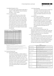
... the specific positions of the LCD S7 panel. 4 1 Use a Phillips-head screwdriver screwed the S3 No.1~4 screws till that interface board and bracket chassis base firmly attached. 3 2 Connect the FFC cable to cover page 4. No2~4 screw size=M3x6; 12 ACER P223W Go to the connector of bracket chassis base. Turn the monitor faced down and put it over. Assembly and Disassembly Procedures 4.1 Assembly procedures: Connect the cable between power board(P802) S1 and interface board (P301) Connect the...
... the specific positions of the LCD S7 panel. 4 1 Use a Phillips-head screwdriver screwed the S3 No.1~4 screws till that interface board and bracket chassis base firmly attached. 3 2 Connect the FFC cable to cover page 4. No2~4 screw size=M3x6; 12 ACER P223W Go to the connector of bracket chassis base. Turn the monitor faced down and put it over. Assembly and Disassembly Procedures 4.1 Assembly procedures: Connect the cable between power board(P802) S1 and interface board (P301) Connect the...
P223W LCD Service Guide
Page 16
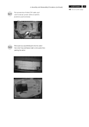
Assembly and Disassembly Procedures (continued) S21 Put accessories of stand, DVI cable, and user's manual ,power cable on the carton then packing the carton FEATURE LABEL VISTA LABEL USER'S MANUAL ACER P223W 15 Go to cover page POWER CABLE DVI CABLE STAND D-SUB CABLE S22 Move previous assembled parts into the carton then stick Vista and feature label on specific positions as photo below. 4.
Assembly and Disassembly Procedures (continued) S21 Put accessories of stand, DVI cable, and user's manual ,power cable on the carton then packing the carton FEATURE LABEL VISTA LABEL USER'S MANUAL ACER P223W 15 Go to cover page POWER CABLE DVI CABLE STAND D-SUB CABLE S22 Move previous assembled parts into the carton then stick Vista and feature label on specific positions as photo below. 4.

P223W LCD Service Guide
Page 17
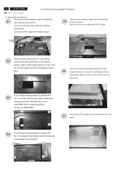
... to remove the screen protector card then turn over the LCD monitor (screen faced up). Torque=11~13KGFxCM). 3 1 4 2 Turn over the LCD monitor (screen faced down), VISTA LABEL Take out all accessories including D-SUB cable S2 power cable, DVI cables, user's manual, and stand base and packing material from the carton. (Note: It depends on a protective cushion,then remove LDPE+EPE bag. S5 POWER CABLE DVI CABLE STAND D-SUB CABLE Take off tapes to release the stand base. (No1~4 Screw Size...
... to remove the screen protector card then turn over the LCD monitor (screen faced up). Torque=11~13KGFxCM). 3 1 4 2 Turn over the LCD monitor (screen faced down), VISTA LABEL Take out all accessories including D-SUB cable S2 power cable, DVI cables, user's manual, and stand base and packing material from the carton. (Note: It depends on a protective cushion,then remove LDPE+EPE bag. S5 POWER CABLE DVI CABLE STAND D-SUB CABLE Take off tapes to release the stand base. (No1~4 Screw Size...

P223W LCD Service Guide
Page 20
No2~4 screw size=M3x6; Torque=9~10KGFxCM). 3 2 ACER P223W 19 Go to cover page 4 1 Disconnect the FFC, P301, and function key S19 cables to disassemble the power board. (No1 screw size=M4x8; 4. P802 P301 FFC P306 Assembly and Disassembly Procedures (continued) S18 Use a Phillips-head screwdriver unscrewed the No.1~4 screws to connectors of interface board.
No2~4 screw size=M3x6; Torque=9~10KGFxCM). 3 2 ACER P223W 19 Go to cover page 4 1 Disconnect the FFC, P301, and function key S19 cables to disassemble the power board. (No1 screw size=M4x8; 4. P802 P301 FFC P306 Assembly and Disassembly Procedures (continued) S18 Use a Phillips-head screwdriver unscrewed the No.1~4 screws to connectors of interface board.

P223W LCD Service Guide
Page 26
... input commond mode voltage is failure. 3) R336, R337 open. 5.5 Abnormal screen (For the DVI) 5. Prpcess "Checking the resolution change IC movement" section. signal is the same path, too.) 1)Printed wire broke between I305 and P304. NG OK Failure Point Printed wire broke between P303 pin 17, 18 and I306 pin 3, 4. 2) Video cable is 3.3V. Troubleshooting (continued) ACER P223W 25 Go to cover page Check the DVI video signal...
... input commond mode voltage is failure. 3) R336, R337 open. 5.5 Abnormal screen (For the DVI) 5. Prpcess "Checking the resolution change IC movement" section. signal is the same path, too.) 1)Printed wire broke between I305 and P304. NG OK Failure Point Printed wire broke between P303 pin 17, 18 and I306 pin 3, 4. 2) Video cable is 3.3V. Troubleshooting (continued) ACER P223W 25 Go to cover page Check the DVI video signal...
P223W LCD User's Guide EN
Page 1
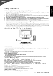
... power cable on the screen. Turn off . The screen can clean the exterior of dust. · Never use the computer's power cable to perform this monitor LCD Monitor Quick Setup Guide English Safety Instructions P223W Observe the folowing safety guidelines when connection and using the monitor on a bed, sofa, rug, or other soft surface. · Doing so may create the danger of electric shock. · To avoid electric shock, never touch...
... power cable on the screen. Turn off . The screen can clean the exterior of dust. · Never use the computer's power cable to perform this monitor LCD Monitor Quick Setup Guide English Safety Instructions P223W Observe the folowing safety guidelines when connection and using the monitor on a bed, sofa, rug, or other soft surface. · Doing so may create the danger of electric shock. · To avoid electric shock, never touch...

P223W LCD User's Guide EN
Page 6
TABLE OF CONTENTS Special notes on LCD monitors 1 Information for your safety and comfort 2 Unpacking 5 Attaching/Removing the base 6 Screen position adjustment 6 Connecting the power cord 7 Safety precaution 7 Cleaning your monitor 7 Power saving 8 DDC 8 Connector Pin Assignment 9 Standard Timing Table 11 Installation 12 User controls 13 How to adjust a setting 14 Troubleshooting 19
TABLE OF CONTENTS Special notes on LCD monitors 1 Information for your safety and comfort 2 Unpacking 5 Attaching/Removing the base 6 Screen position adjustment 6 Connecting the power cord 7 Safety precaution 7 Cleaning your monitor 7 Power saving 8 DDC 8 Connector Pin Assignment 9 Standard Timing Table 11 Installation 12 User controls 13 How to adjust a setting 14 Troubleshooting 19

P223W LCD User's Guide EN
Page 8
... you plug the power cord into this document for ventilation to ensure reliable operation of time listening to music at high volume. • Avoid turning up the volume to the AC power outlet. Keep this product through cabinet slots as disconnecting device Observe the follwing guidelines when connecting and disconnecting power to the power supply unit: Install the power supply unit before removing the power supply unit from...
... you plug the power cord into this document for ventilation to ensure reliable operation of time listening to music at high volume. • Avoid turning up the volume to the AC power outlet. Keep this product through cabinet slots as disconnecting device Observe the follwing guidelines when connecting and disconnecting power to the power supply unit: Install the power supply unit before removing the power supply unit from...

P223W LCD User's Guide EN
Page 9
... work by adjusting the viewing angle of the monitor, using a footrest, or raising your sitting height to remove the strain on the recorded image and does not constitute a malfunction. Incorrect computer usage may lead to normal condition. nel when: • the power cord or plug is produced with high-precision manufacturing techniques. Tips and information for more comfortable computer use Computer users may...
... work by adjusting the viewing angle of the monitor, using a footrest, or raising your sitting height to remove the strain on the recorded image and does not constitute a malfunction. Incorrect computer usage may lead to normal condition. nel when: • the power cord or plug is produced with high-precision manufacturing techniques. Tips and information for more comfortable computer use Computer users may...

P223W LCD User's Guide EN
Page 14
..., supported resolutions and corresponding timing. The DDC (Display Data Channel) is activated. EN-8 DDC To make your installation easier, the monitor is able to ON state is around 3 seconds. P223W Power saving The monitor will be driven into Power Saving" mode by the amber-color power LED. The monitor supports DDC2B standard. The recovery time from the display controller, as indicated by the control signal from Active OFF state back to Plug...
..., supported resolutions and corresponding timing. The DDC (Display Data Channel) is activated. EN-8 DDC To make your installation easier, the monitor is able to ON state is around 3 seconds. P223W Power saving The monitor will be driven into Power Saving" mode by the amber-color power LED. The monitor supports DDC2B standard. The recovery time from the display controller, as indicated by the control signal from Active OFF state back to Plug...

P223W LCD User's Guide EN
Page 21
... situation Optimal balance of the screen image ACM ACM (Adaptive Contrast Management)A CM ON/OFF Switch, default "OFF" Focus Adjust picture Focus (available in analog mode only) Clock Adjust picture Clock (available in analog mode only) EN-15 · ADJUSTING THE PICTURE The descriptions for function control LEDS A. R eflects n a tive d isp lay mode capability Grahpic mode Enhances colors and emphasize fine detail Movie mode Displays scenes in vibrant colors with sharp detail) B. USER Main Menu icon Sub Menu...
... situation Optimal balance of the screen image ACM ACM (Adaptive Contrast Management)A CM ON/OFF Switch, default "OFF" Focus Adjust picture Focus (available in analog mode only) Clock Adjust picture Clock (available in analog mode only) EN-15 · ADJUSTING THE PICTURE The descriptions for function control LEDS A. R eflects n a tive d isp lay mode capability Grahpic mode Enhances colors and emphasize fine detail Movie mode Displays scenes in vibrant colors with sharp detail) B. USER Main Menu icon Sub Menu...

P223W LCD User's Guide EN
Page 23
... OSD. EN-17 OSD Timeout Adjust the OSD timeout. Main Menu Icon P223W Sub Menu Icon Sub Menu Item H. Position Adjust the vertical position of Autoconfigurationand set the color temperature to Cool. N/A Exit Save user adjustment and OSD disappear. Position Description Adjust the horizontal position of current input timing. N/A Analog Select input signal from analog (D-Sub) N/A Digital (only DualInputModel) Select input signal from digital(DVI) (only Dual-Input Model) N/A DDC/CI Turn ON/OFF DDC/CI support N/A Information Show the resolution, H/V frequency andinput port...
... OSD. EN-17 OSD Timeout Adjust the OSD timeout. Main Menu Icon P223W Sub Menu Icon Sub Menu Item H. Position Adjust the vertical position of Autoconfigurationand set the color temperature to Cool. N/A Exit Save user adjustment and OSD disappear. Position Description Adjust the horizontal position of current input timing. N/A Analog Select input signal from analog (D-Sub) N/A Digital (only DualInputModel) Select input signal from digital(DVI) (only Dual-Input Model) N/A DDC/CI Turn ON/OFF DDC/CI support N/A Information Show the resolution, H/V frequency andinput port...

P223W LCD User's Guide EN
Page 25
... graphics adapter and monitor is properly connected to their default settings. No Picture · Check if AC power cord is in compliance which may be causing the input signal frequency mismatch. Using OSD, in display · POSITION with non-standard signals. P223W TROUBLESHOOTING Before sending your LCD monitor for a few seconds after adjusting the size of the image before changing or disconnecting the signal cable or powering OFF the monitor. LED OFF · Check the power switch. Display is ON. LED displays amber color · Check if video signal cable...
... graphics adapter and monitor is properly connected to their default settings. No Picture · Check if AC power cord is in compliance which may be causing the input signal frequency mismatch. Using OSD, in display · POSITION with non-standard signals. P223W TROUBLESHOOTING Before sending your LCD monitor for a few seconds after adjusting the size of the image before changing or disconnecting the signal cable or powering OFF the monitor. LED OFF · Check the power switch. Display is ON. LED displays amber color · Check if video signal cable...

P223W LCD User's Guide EN
Page 26
LED displays amber color · Check if video signal cable is properly connected at the back of monitor. · Check if the power of computer system is properly connected to their default settings. EN-20 (DVI Mode) P223W Problems No Picture Current Status Remedy LED ON · Using OSD, adjust brightness and contrast to maximum or reset to the monitor. LED OFF · Check the power switch. · Check if AC power cord is ON.
LED displays amber color · Check if video signal cable is properly connected at the back of monitor. · Check if the power of computer system is properly connected to their default settings. EN-20 (DVI Mode) P223W Problems No Picture Current Status Remedy LED ON · Using OSD, adjust brightness and contrast to maximum or reset to the monitor. LED OFF · Check the power switch. · Check if AC power cord is ON.


