
Service Guide
Page 6
... Infomation 33 Main 34 Advanced 36 Security 37 Boot 41 Exit 42 BIOS Flash Utility 43 Chapter 3 Machine Disassembly and Replacement 45 General Information 46 Before You Begin 46 Disassembly Procedure Flowchart 47 Removing the Battery Pack 50 Removing the Optical Module/HDD Module/Wireless Lan Card and LCD...module . .51 Removing the Optical Module 51 Removing the HDD Module 51 Removing the Wireless LAN Card 51 Removing the LCD Module 52 Disassembling the Main Unit 53 Remove the function key board and the keyboard 53 Separate the main unit into the logic upper and the logic ...
... Infomation 33 Main 34 Advanced 36 Security 37 Boot 41 Exit 42 BIOS Flash Utility 43 Chapter 3 Machine Disassembly and Replacement 45 General Information 46 Before You Begin 46 Disassembly Procedure Flowchart 47 Removing the Battery Pack 50 Removing the Optical Module/HDD Module/Wireless Lan Card and LCD...module . .51 Removing the Optical Module 51 Removing the HDD Module 51 Removing the Wireless LAN Card 51 Removing the LCD Module 52 Disassembling the Main Unit 53 Remove the function key board and the keyboard 53 Separate the main unit into the logic upper and the logic ...
Service Guide
Page 7
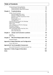
Table of Contents Disassembling the External Modules 59 Disassembling the HDD Module 59 Disassembling the Optical Drive Module 59 Chapter 4 Troubleshooting 61 System Check Procedures 62 External Diskette Drive Check 62 External CD-ROM Drive Check... 85 Top View 85 Bottom View 86 Chapter 6 FRU (Field Replaceable Unit) List 87 Exploded Diagram 88 Appendix A Model Definition and Configuration 96 Ferrari 3200 Series 96 Appendix B Test Compatible Components 97 Microsoft® Windows® XP Home Environment Test 98 Appendix C Online Support Information 101 Index ...
Table of Contents Disassembling the External Modules 59 Disassembling the HDD Module 59 Disassembling the Optical Drive Module 59 Chapter 4 Troubleshooting 61 System Check Procedures 62 External Diskette Drive Check 62 External CD-ROM Drive Check... 85 Top View 85 Bottom View 86 Chapter 6 FRU (Field Replaceable Unit) List 87 Exploded Diagram 88 Appendix A Model Definition and Configuration 96 Ferrari 3200 Series 96 Appendix B Test Compatible Components 97 Microsoft® Windows® XP Home Environment Test 98 Appendix C Online Support Information 101 Index ...
Service Guide
Page 52
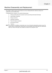
..., group the screws with the corresponding components to disassemble the notebook computer for the different components vary in size. When you need the following tools: T Wrist grounding strap and conductive mat for preventing ...T Plastic flat blade screwdriver T Hex wrench (2.5mm) T Tweezers NOTE: The screws for maintenance and troubleshooting. To disassemble the computer, you remove the stripe cover, please be careful not to scrape the cover. Chapter 3 Machine Disassembly and Replacement This chapter contains step-by-step procedures on how to avoid mismatch when putting back...
..., group the screws with the corresponding components to disassemble the notebook computer for the different components vary in size. When you need the following tools: T Wrist grounding strap and conductive mat for preventing ...T Plastic flat blade screwdriver T Hex wrench (2.5mm) T Tweezers NOTE: The screws for maintenance and troubleshooting. To disassemble the computer, you remove the stripe cover, please be careful not to scrape the cover. Chapter 3 Machine Disassembly and Replacement This chapter contains step-by-step procedures on how to avoid mismatch when putting back...
Service Guide
Page 53
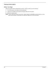
General Information Before You Begin Before proceeding with the disassembly procedure, make sure that you disconnect different FFC/FPC/connectors. 46 Chapter 3 Remove the battery pack. Unplug the AC adapter and all peripherals. 2. Turn off the power to tear the tape or mylar before you do the following: 1. NOTE: Ferrari 3200 series product uses mylar or tape to fasten the FFC/FPC/connectors/cable, you may need to the system and all power and signal cables from the system. 3.
General Information Before You Begin Before proceeding with the disassembly procedure, make sure that you disconnect different FFC/FPC/connectors. 46 Chapter 3 Remove the battery pack. Unplug the AC adapter and all peripherals. 2. Turn off the power to tear the tape or mylar before you do the following: 1. NOTE: Ferrari 3200 series product uses mylar or tape to fasten the FFC/FPC/connectors/cable, you may need to the system and all power and signal cables from the system. 3.
Service Guide
Page 54
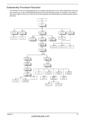
... The flowchart on the succeeding page gives you a graphic representation on the entire disassembly sequence and instructs you on the components that order. Start Battery Hx2 HDD Door Hx2 Dimm Door HDD Module Memory Hx2 Mx3 Keyboard Ox4 Middle ... 4-in that need to remove the system board, you want to be removed during servicing. For example, if you must first remove the keyboard, then disassemble the inside assembly frame in -1 Card Rearder Fx2 Smart Card Reader Hx1 Top Cover Shielding Tx2 HDD Bracket Hx2 Modem/ Bluetooth Combo Card Ex4 Thermal...
... The flowchart on the succeeding page gives you a graphic representation on the entire disassembly sequence and instructs you on the components that order. Start Battery Hx2 HDD Door Hx2 Dimm Door HDD Module Memory Hx2 Mx3 Keyboard Ox4 Middle ... 4-in that need to remove the system board, you want to be removed during servicing. For example, if you must first remove the keyboard, then disassemble the inside assembly frame in -1 Card Rearder Fx2 Smart Card Reader Hx1 Top Cover Shielding Tx2 HDD Bracket Hx2 Modem/ Bluetooth Combo Card Ex4 Thermal...
Service Guide
Page 60
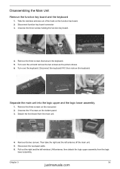
... connector 3. Then take the right and the left wireless LAN antenna, then detach the logic upper assembly from the main unit. 4. Chapter 3 53 justmanuals.com Disassembling the Main Unit Remove the function key board and the keyboard 1. Remove the two screws.
... connector 3. Then take the right and the left wireless LAN antenna, then detach the logic upper assembly from the main unit. 4. Chapter 3 53 justmanuals.com Disassembling the Main Unit Remove the function key board and the keyboard 1. Remove the two screws.
Service Guide
Page 61
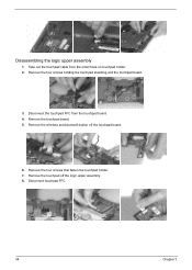
Remove the touchpad board. 5. Remove the four screws holding the touchpad shielding and the touchpad board. 3. Remove the four screws that fasten the touchpad holder. 7. Disconnect touchpad FFC. 54 Chapter 3 Remove the wireless and bluetooth button off the logic upper assembly. 8. Disassembling the logic upper assembly 1. Take out the touchpad cable from the touchpad board. 4. Disconnect the touchpad FFC from the small hook on touchpad holder. 2. Remove the touchpad off the touchpad board. 6.
Remove the touchpad board. 5. Remove the four screws holding the touchpad shielding and the touchpad board. 3. Remove the four screws that fasten the touchpad holder. 7. Disconnect touchpad FFC. 54 Chapter 3 Remove the wireless and bluetooth button off the logic upper assembly. 8. Disassembling the logic upper assembly 1. Take out the touchpad cable from the touchpad board. 4. Disconnect the touchpad FFC from the small hook on touchpad holder. 2. Remove the touchpad off the touchpad board. 6.
Service Guide
Page 62
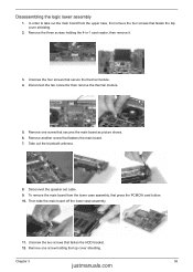
... main board. 7. Remove another screw that fasten the HDD bracket. 12. Disconnect the speaker set cable. 9. Remove the three screws holding the top cover shielding. Disassembling the logic lower assembly 1. Unscrew the four screws that secure the thermal module. 4.
... main board. 7. Remove another screw that fasten the HDD bracket. 12. Disconnect the speaker set cable. 9. Remove the three screws holding the top cover shielding. Disassembling the logic lower assembly 1. Unscrew the four screws that secure the thermal module. 4.
Service Guide
Page 64
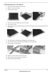
... LCD coaxial cable. 8. Chapter 3 57 justmanuals.com Then remove the right and the left LCD brackets. Disconnect LCD inverter. 4. Disconnect the LCD coaxial cable. . 10. Disassembling the LCD Module 1. Remove the six screw pad and the six screws. 2. Remove the LCD latch kit bracket. Tear off the electric conductive tape that...
... LCD coaxial cable. 8. Chapter 3 57 justmanuals.com Then remove the right and the left LCD brackets. Disconnect LCD inverter. 4. Disconnect the LCD coaxial cable. . 10. Disassembling the LCD Module 1. Remove the six screw pad and the six screws. 2. Remove the LCD latch kit bracket. Tear off the electric conductive tape that...
Service Guide
Page 66
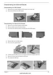
... holding the ODD bracket. 2. two on the back side of the ODD module. 4. Remove another screw as the picture shows. 3. Then remove the optical bracket. 6. Disassembling the Optical Drive Module 1. Slide the ODD from the HDD bracket. Chapter 3 59 justmanuals.com Then detach the ODD door. In order to open the... remove the last two screws on each side. 2. Take out the HDD from the ODD bracket. 5. Remove the three screws that fasten the ODD door. 8. Disassembling the External Modules Disassembling the HDD Module 1. Remove the two screws holding the HDD bracket;
... holding the ODD bracket. 2. two on the back side of the ODD module. 4. Remove another screw as the picture shows. 3. Then remove the optical bracket. 6. Disassembling the Optical Drive Module 1. Slide the ODD from the HDD bracket. Chapter 3 59 justmanuals.com Then detach the ODD door. In order to open the... remove the last two screws on each side. 2. Take out the HDD from the ODD bracket. 5. Remove the three screws that fasten the ODD door. 8. Disassembling the External Modules Disassembling the HDD Module 1. Remove the two screws holding the HDD bracket;
Service Guide
Page 68
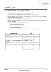
... and secured; POST detects an error and displayed messages on page 77 Chapter 4 61 justmanuals.com Non-Acer products, prototype cards, or modified options can check the following: power cords are intended to . Disassemble and assemble the unit without any problem occurs, you can perform visual inspection before you fellow this model...
... and secured; POST detects an error and displayed messages on page 77 Chapter 4 61 justmanuals.com Non-Acer products, prototype cards, or modified options can check the following: power cords are intended to . Disassemble and assemble the unit without any problem occurs, you can perform visual inspection before you fellow this model...

Service Guide
Page 110
... CPU core voltage 22 package 22 type 22 D DIMM Index Combinations 23 external 51 package 22 removing 51 socket number 22 Speed 22 voltage 22 Disassembly Battery Pack 48 CD-ROM/DVD-ROM Module 53 Floppy Disk Drive 57 Procedure Flowchart 47 Display Standby Mode 29 E Embedded Numeric Keypad 14 Environmental...
... CPU core voltage 22 package 22 type 22 D DIMM Index Combinations 23 external 51 package 22 removing 51 socket number 22 Speed 22 voltage 22 Disassembly Battery Pack 48 CD-ROM/DVD-ROM Module 53 Floppy Disk Drive 57 Procedure Flowchart 47 Display Standby Mode 29 E Embedded Numeric Keypad 14 Environmental...


