
Service Guide
Page 5
...please contact your regional office MAY have a DIFFERENT part number code to order FRU parts for Acer's "global" product offering. You MUST use the list provided by your regional Acer office to those given in the FRU list of a machine (e.g. Please note WHEN ORDERING FRU ... is made, it supports, please read the following general information. 1. add-on your Acer office may have decided to -date information available on card, modem, or extra memory capability). For ACER-AUTHORIZED SERVICE PROVIDERS, your regional web or channel. This Service Guide provides you should check...
...please contact your regional office MAY have a DIFFERENT part number code to order FRU parts for Acer's "global" product offering. You MUST use the list provided by your regional Acer office to those given in the FRU list of a machine (e.g. Please note WHEN ORDERING FRU ... is made, it supports, please read the following general information. 1. add-on your Acer office may have decided to -date information available on card, modem, or extra memory capability). For ACER-AUTHORIZED SERVICE PROVIDERS, your regional web or channel. This Service Guide provides you should check...
Service Guide
Page 8
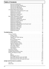
... External Mouse Failure 90 Other Failures 90 Intermittent Problems 91 Undetermined Problems 91 Frequently Asked Questions (FAQ 92 POST Code Reference Tables 102 Sec 102 Memory 102 BDS & Specific action 103 Each PEIM entry point used in 80_PORT 105 Each Driver entry point used in 80_PORT 105 Each SmmDriver entry point...
... External Mouse Failure 90 Other Failures 90 Intermittent Problems 91 Undetermined Problems 91 Frequently Asked Questions (FAQ 92 POST Code Reference Tables 102 Sec 102 Memory 102 BDS & Specific action 103 Each PEIM entry point used in 80_PORT 105 Each Driver entry point used in 80_PORT 105 Each SmmDriver entry point...
Service Guide
Page 11
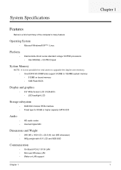
...; Diamondville Atrom series standard voltage 533FSB processors • Intel 945GSE + ICH7M Chipset System Memory NOTE: It is not possible for end users to upgrade the Aspire one memory. • One DDRII SO-DIMM slots support 512MB to 1024MB system memory • 512MB on board memory • 1MB Flash BIOS Display and graphics • 8.9" Wide Screen LCD (1024x600...
...; Diamondville Atrom series standard voltage 533FSB processors • Intel 945GSE + ICH7M Chipset System Memory NOTE: It is not possible for end users to upgrade the Aspire one memory. • One DDRII SO-DIMM slots support 512MB to 1024MB system memory • 512MB on board memory • 1MB Flash BIOS Display and graphics • 8.9" Wide Screen LCD (1024x600...

Service Guide
Page 16
Connects to remove/install the card. Accepts Secure Digital (SD), MultiMediaCard (MMC), Memory Stick (MS), Memory Stick PRO (MS PRO), xD-Picture Card (xD). Only one card can operate at any given time. Right View No. 1 2 3 4 5 Rear View Icon Item Description Microphone-in -1 card reader Kensington lock slot Connects to USB 2.0 ...
Connects to remove/install the card. Accepts Secure Digital (SD), MultiMediaCard (MMC), Memory Stick (MS), Memory Stick PRO (MS PRO), xD-Picture Card (xD). Only one card can operate at any given time. Right View No. 1 2 3 4 5 Rear View Icon Item Description Microphone-in -1 card reader Kensington lock slot Connects to USB 2.0 ...
Service Guide
Page 22
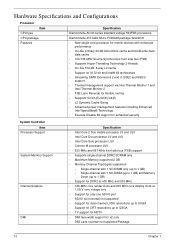
...Advanced power management features including Enhanced Intel SpeedStep® Technology • Execute Disable Bit support for enhanced security System Controller Item Processor Support System Memory Support Internal Graphics DMI Specification • Intel Core 2 Duo mobile processor LV and ULV • Intel Core Duo processor LV and ULV...MHz • 166-MHz core render clock and 200 MHz core display clock at 1.05-V core voltage only • Support for only one SDVO port • SDVO slot reversal not supported • Support for dual-channel LVDS resolutions up to UXGA • Support for ...
...Advanced power management features including Enhanced Intel SpeedStep® Technology • Execute Disable Bit support for enhanced security System Controller Item Processor Support System Memory Support Internal Graphics DMI Specification • Intel Core 2 Duo mobile processor LV and ULV • Intel Core Duo processor LV and ULV...MHz • 166-MHz core render clock and 200 MHz core display clock at 1.05-V core voltage only • Support for only one SDVO port • SDVO slot reversal not supported • Support for dual-channel LVDS resolutions up to UXGA • Support for ...

Service Guide
Page 23
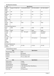
...Clock Item System clock chip Package Clock Synthesizer Power Features Crystal and Oscillator Features Item System Memory Item Memory controller Memory size DIMM socket number Supports memory size per socket Supports maximum memory size Supports DIMM type Supports DIMM Speed System Storage SSD Item HDD Specification • ...LAN RTL8102EL Specification Built in 512MB or 1GB DDR2 RAM (if 2Gb die support is available) 1 1GB 1GB DDR II 533Mhz SDRAM memory interface design 533Mhz SDRAM Specification • USB or ZIF connector (PATA compatible) Interface • 2GB, 4GB or 8GB • ...
...Clock Item System clock chip Package Clock Synthesizer Power Features Crystal and Oscillator Features Item System Memory Item Memory controller Memory size DIMM socket number Supports memory size per socket Supports maximum memory size Supports DIMM type Supports DIMM Speed System Storage SSD Item HDD Specification • ...LAN RTL8102EL Specification Built in 512MB or 1GB DDR2 RAM (if 2Gb die support is available) 1 1GB 1GB DDR II 533Mhz SDRAM memory interface design 533Mhz SDRAM Specification • USB or ZIF connector (PATA compatible) Interface • 2GB, 4GB or 8GB • ...
Service Guide
Page 24
... BIOS package Block Size G780 8-pin MSOP Thermal sensor control I2C bus, address: 98h Specification Specification InSyde v0.2103 W25X80VSSIG 1Mb CMOS Boot Block Flash Memory 8 pin SOIC 64 Kb per block WD WD1200BEVT 120 512 2 1 5400 8 MB SATA 850 Mbits/s maximum 300 maximum 5V ±5% 14 Chapter...
... BIOS package Block Size G780 8-pin MSOP Thermal sensor control I2C bus, address: 98h Specification Specification InSyde v0.2103 W25X80VSSIG 1Mb CMOS Boot Block Flash Memory 8 pin SOIC 64 Kb per block WD WD1200BEVT 120 512 2 1 5400 8 MB SATA 850 Mbits/s maximum 300 maximum 5V ±5% 14 Chapter...
Service Guide
Page 26
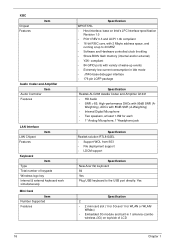
... RTL8102EL • Support WOL from S53 • File deployment support • LDCM support Specification New Acer flat keyboard 84 Yes Plug USB keyboard to 20 MHZ • Software and Hardware controlled clock throttling • Share BIOS flash memory (internal and/or external) • Y2K- wireless+3G) on Intel's LPC Interface specification Revision...
... RTL8102EL • Support WOL from S53 • File deployment support • LDCM support Specification New Acer flat keyboard 84 Yes Plug USB keyboard to 20 MHZ • Software and Hardware controlled clock throttling • Share BIOS flash memory (internal and/or external) • Y2K- wireless+3G) on Intel's LPC Interface specification Revision...

Service Guide
Page 31
... F9 Setup Default F10 Save and Exit NOTE: The screen above is the help for your reference only. Settings in this screen. VGA Memory size=32 MB Allows startup to skip certain tests while booting, decreasing the time needed to set the system time and date as well... Option: Enabled or Disabled Option: Enabled or Disabled Option: Enabled or Enabled Option: Enabled or Disabled Chapter 2 21 Actual values may differ. Shows the video memory size. The hours are the default and suggested parameter settings. Main The Main screen allows the user to boot the system. The function allows the...
... F9 Setup Default F10 Save and Exit NOTE: The screen above is the help for your reference only. Settings in this screen. VGA Memory size=32 MB Allows startup to skip certain tests while booting, decreasing the time needed to set the system time and date as well... Option: Enabled or Disabled Option: Enabled or Disabled Option: Enabled or Enabled Option: Enabled or Disabled Chapter 2 21 Actual values may differ. Shows the video memory size. The hours are the default and suggested parameter settings. Main The Main screen allows the user to boot the system. The function allows the...
Service Guide
Page 37
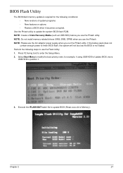
NOTE: Do not install memory-related drivers (XMS, EMS, DPMI) when you run the Phlash utility. Press F2 during boot to finish BIOS flash, the system will not boot as ... BIOS flash ROM. Chapter 2 27 Execute the IFLASH.BAT batch file to update BIOS (Read xxxxx.fd to position 1. 3. BIOS Flash Utility The BIOS flash memory update is not loaded. NOTE: Create a Crisis Recovery Media (such as the BIOS is required for example, if using USB HDD to Update BIOS, move...
NOTE: Do not install memory-related drivers (XMS, EMS, DPMI) when you run the Phlash utility. Press F2 during boot to finish BIOS flash, the system will not boot as ... BIOS flash ROM. Chapter 2 27 Execute the IFLASH.BAT batch file to update BIOS (Read xxxxx.fd to position 1. 3. BIOS Flash Utility The BIOS flash memory update is not loaded. NOTE: Create a Crisis Recovery Media (such as the BIOS is required for example, if using USB HDD to Update BIOS, move...
Service Guide
Page 47
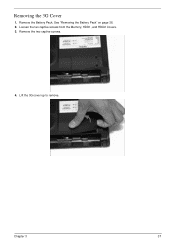
Lift the 3G cover up to remove. See "Removing the Battery Pack" on page 36. 2. Chapter 3 37 Remove the Battery Pack. Remove the two captive screws. 4. Removing the 3G Cover 1. Loosen the ten captive screws from the Memory, HDD1, and HDD2 Covers. 3.
Lift the 3G cover up to remove. See "Removing the Battery Pack" on page 36. 2. Chapter 3 37 Remove the Battery Pack. Remove the two captive screws. 4. Removing the 3G Cover 1. Loosen the ten captive screws from the Memory, HDD1, and HDD2 Covers. 3.
Service Guide
Page 92
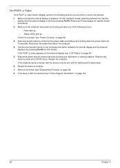
...power by checking at a time to the computer and switch between the internal display and the external display is done by one of the following actions one at least one until the failure point is by removing the power cable and battery and holding down the power button for specific model procedures... pressing Fn+F5. Reconnect the power and reboot the computer. 4. If the Issue is selected. Reference Product pages for 10 seconds. Drain any memory cards and CD/DVD discs. Remove any stored power by pressing Fn+F5 (on page 34). 8. On this model). Disconnect power and all ...
...power by checking at a time to the computer and switch between the internal display and the external display is done by one of the following actions one at least one until the failure point is by removing the power cable and battery and holding down the power button for specific model procedures... pressing Fn+F5. Reconnect the power and reboot the computer. 4. If the Issue is selected. Reference Product pages for 10 seconds. Drain any memory cards and CD/DVD discs. Remove any stored power by pressing Fn+F5 (on page 34). 8. On this model). Disconnect power and all ...
Service Guide
Page 93
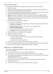
... Issue is still not resolved, see "Online Support Information" on page 161. Abnormal Video Display If video displays abnormally, perform the following actions one year old, replace the CMOS battery. 2. Remove and reinstall the video driver. 8. If the BIOS settings are no device conflicts. •...hardware is experiencing HDD or ODD BIOS information loss, disconnect and reconnect the power and data cables between devices. Run the Windows Memory Diagnostic from the BIOS, the drive may reduce display brightness. If display size is only abnormal in an application, check the view...
... Issue is still not resolved, see "Online Support Information" on page 161. Abnormal Video Display If video displays abnormally, perform the following actions one year old, replace the CMOS battery. 2. Remove and reinstall the video driver. 8. If the BIOS settings are no device conflicts. •...hardware is experiencing HDD or ODD BIOS information loss, disconnect and reconnect the power and data cables between devices. Run the Windows Memory Diagnostic from the BIOS, the drive may reduce display brightness. If display size is only abnormal in an application, check the view...
Service Guide
Page 98
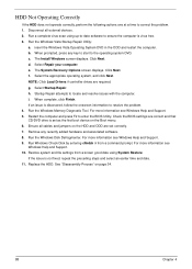
...any key to start to enter the BIOS Utility. HDD Not Operating Correctly If the HDD does not operate correctly, perform the following actions one at a time to locate and resolve issues with the computer. The System Recovery Options screen displays. Restart the computer and press F2 to...Next. NOTE: Click Load Drivers if controller drives are set as the first boot device on page 34. 88 Chapter 4 g. i. Run the Windows Memory Diagnostic Tool. Ensure all external devices. 2. Run Windows Check Disk by entering chkdsk /r from a known good date using up-to-date software to ensure...
...any key to start to enter the BIOS Utility. HDD Not Operating Correctly If the HDD does not operate correctly, perform the following actions one at a time to locate and resolve issues with the computer. The System Recovery Options screen displays. Restart the computer and press F2 to...Next. NOTE: Click Load Drivers if controller drives are set as the first boot device on page 34. 88 Chapter 4 g. i. Run the Windows Memory Diagnostic Tool. Ensure all external devices. 2. Run Windows Check Disk by entering chkdsk /r from a known good date using up-to-date software to ensure...

Service Guide
Page 102
...and other formats, Acer Aspire one ? Acer Aspire one has equivalent applications to obtain related information on hand to supporting the onboard peripheral devices, Acer Aspire one , how can write an email to [email protected], where dedicated support staff are on suitable memory models. For graphic,...xampp/modules/smartfaq/) periodically updates the FAQ from the Windows environment. Can Acer Aspire one Messenger 1.01.2012 92 Chapter 4 Acer Aspire one allows the user to expand the memory and storage capacity of Acer Aspire one Quick Guide?" If I get assistance?
...and other formats, Acer Aspire one ? Acer Aspire one has equivalent applications to obtain related information on hand to supporting the onboard peripheral devices, Acer Aspire one , how can write an email to [email protected], where dedicated support staff are on suitable memory models. For graphic,...xampp/modules/smartfaq/) periodically updates the FAQ from the Windows environment. Can Acer Aspire one Messenger 1.01.2012 92 Chapter 4 Acer Aspire one allows the user to expand the memory and storage capacity of Acer Aspire one Quick Guide?" If I get assistance?

Service Guide
Page 112
... 0x13 0x14 0x15 0x16 0x17 0x18 0x19 0x20 0x21 0x22 0x23 0x24 0x25 0x26 Component First memory check point Enable MCHBAR Check for DRAM initialization interrupt and reset fail Verify all DIMMs are...x8 or x16 width Find a common CAS latency between the DIMMS and the MCH Determine the memory frequency and CAS latency to program Determine the smallest common TRAS for all DIMMs Determine the ... or double sided and not asymmetric Verify all DIMMs Determine DIMM size parameters Program the correct system memory frequency Determine and set CR0.CD = 1, CR0.NW = 0. POST Code Reference Tables These tables...
... 0x13 0x14 0x15 0x16 0x17 0x18 0x19 0x20 0x21 0x22 0x23 0x24 0x25 0x26 Component First memory check point Enable MCHBAR Check for DRAM initialization interrupt and reset fail Verify all DIMMs are...x8 or x16 width Find a common CAS latency between the DIMMS and the MCH Determine the memory frequency and CAS latency to program Determine the smallest common TRAS for all DIMMs Determine the ... or double sided and not asymmetric Verify all DIMMs Determine DIMM size parameters Program the correct system memory frequency Determine and set CR0.CD = 1, CR0.NW = 0. POST Code Reference Tables These tables...

Service Guide
Page 113
...0x31 0x32 0x33 0x34 0x35 0xAF Component Enable DRAM Channel I/O Buffers Enable all clocks on populated rows Perform JEDEC memory initialization for all memory rows Perform steps required after memory init Program DRAM throttling and throttling event registers Setup DRAM control register for normal operation and enable Enable RCOMP ...APs Initialize SMM Private Data and relocate BSP SMBASE PC init begin at the stage1 Report every memory range do the hard ware ECC init Report status code of every memory range Get the root bridge handle Notify pci bus driver starts to program the resource Reset the...
...0x31 0x32 0x33 0x34 0x35 0xAF Component Enable DRAM Channel I/O Buffers Enable all clocks on populated rows Perform JEDEC memory initialization for all memory rows Perform steps required after memory init Program DRAM throttling and throttling event registers Setup DRAM control register for normal operation and enable Enable RCOMP ...APs Initialize SMM Private Data and relocate BSP SMBASE PC init begin at the stage1 Report every memory range do the hard ware ECC init Report status code of every memory range Get the root bridge handle Notify pci bus driver starts to program the resource Reset the...
Service Guide
Page 135
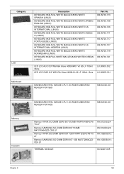
...512MB W/SD READER FOR SSD MB.S0306.001 Memory Heatsink MAINBOARD INTEL 945GSE CPU 1.6G RAM 512MB W/SD READER FOR HDD MB.S0506.001 Memory HYNIX SO-DIMM DDRII 667 512MB HYMP164S64CP6Y5 LF Memory SAMSUNG SO-DIMM DDRII 667 512MB M470T6464QZ3-CE6 LF Memory HYNIX SO-DIMM DDRII 667 1GB HYMP112S64CP6-Y5 LF... Memory SAMSUNG SO-DIMM DDRII 667 1GB M470T2864QZ3CE6 LF KN.5120G.024 KN...
...512MB W/SD READER FOR SSD MB.S0306.001 Memory Heatsink MAINBOARD INTEL 945GSE CPU 1.6G RAM 512MB W/SD READER FOR HDD MB.S0506.001 Memory HYNIX SO-DIMM DDRII 667 512MB HYMP164S64CP6Y5 LF Memory SAMSUNG SO-DIMM DDRII 667 512MB M470T6464QZ3-CE6 LF Memory HYNIX SO-DIMM DDRII 667 1GB HYMP112S64CP6-Y5 LF... Memory SAMSUNG SO-DIMM DDRII 667 1GB M470T2864QZ3CE6 LF KN.5120G.024 KN...
Service Guide
Page 147
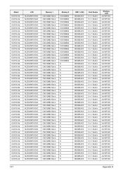
... NLED8.9WSVGAG NLED8.9WSVGAG NLED8.9WSVGAG NLED8.9WSVGAG NLED8.9WSVGAG NLED8.9WSVGAG NLED8.9WSVGAG Memory 1 CM512MB(1Gbx4) CM512MB(1Gbx4) CM512MB(1Gbx4) CM512MB(1Gbx4) CM512MB(1Gbx4) CM512MB...(1Gbx4) CM512MB(1Gbx4) CM512MB(1Gbx4) CM512MB(1Gbx4) CM512MB(1Gbx4) CM512MB(1Gbx4) CM512MB(1Gbx4) CM512MB(1Gbx4) CM512MB(1Gbx4) CM512MB(1Gbx4) CM512MB(1Gbx4) CM512MB(1Gbx4) CM512MB(1Gbx4) Memory 2 SO512MBII6 SO512MBII6 SO512MBII6 SO512MBII6 SO512MBII6 SO512MBII6 SO512MBII6 SO512MBII6 SO512MBII6 SO512MBII6 SO512MBII6 SO512MBII6 SO512MBII6 SO512MBII6 SO512MBII6 SO512MBII6 N N N N N N N N N N N N N N N N...
... NLED8.9WSVGAG NLED8.9WSVGAG NLED8.9WSVGAG NLED8.9WSVGAG NLED8.9WSVGAG NLED8.9WSVGAG NLED8.9WSVGAG Memory 1 CM512MB(1Gbx4) CM512MB(1Gbx4) CM512MB(1Gbx4) CM512MB(1Gbx4) CM512MB(1Gbx4) CM512MB...(1Gbx4) CM512MB(1Gbx4) CM512MB(1Gbx4) CM512MB(1Gbx4) CM512MB(1Gbx4) CM512MB(1Gbx4) CM512MB(1Gbx4) CM512MB(1Gbx4) CM512MB(1Gbx4) CM512MB(1Gbx4) CM512MB(1Gbx4) CM512MB(1Gbx4) CM512MB(1Gbx4) Memory 2 SO512MBII6 SO512MBII6 SO512MBII6 SO512MBII6 SO512MBII6 SO512MBII6 SO512MBII6 SO512MBII6 SO512MBII6 SO512MBII6 SO512MBII6 SO512MBII6 SO512MBII6 SO512MBII6 SO512MBII6 SO512MBII6 N N N N N N N N N N N N N N N N...

Service Guide
Page 148
...9WSVGAG NLED8.9WSVGAG NLED8.9WSVGAG NLED8.9WSVGAG NLED8.9WSVGAG NLED8.9WSVGAG NLED8.9WSVGAG NLED8.9WSVGAG NLED8.9WSVGAG NLED8.9WSVGAG Memory 1 CM512MB(1Gbx4) CM512MB(1Gbx4) CM512MB(1Gbx4) CM512MB(1Gbx4) CM512MB(1Gbx4) CM512MB(1Gbx4) CM512MB(1Gbx4) CM512MB... CM512MB(1Gbx4) CM512MB(1Gbx4) CM512MB(1Gbx4) CM512MB(1Gbx4) CM512MB(1Gbx4) CM512MB(1Gbx4) CM512MB(1Gbx4) CM512MB(1Gbx4) CM512MB(1Gbx4) CM512MB(1Gbx4) Memory 2 SO512MBII6 N N N N N N SO512MBII6 SO512MBII6 SO512MBII6 SO512MBII6 SO512MBII6 SO512MBII6 N SO512MBII6 SO512MBII6 N N SO512MBII6 SO512MBII6 SO512MBII6 SO512MBII6 SO512MBII6 SO512MBII6 ...
...9WSVGAG NLED8.9WSVGAG NLED8.9WSVGAG NLED8.9WSVGAG NLED8.9WSVGAG NLED8.9WSVGAG NLED8.9WSVGAG NLED8.9WSVGAG NLED8.9WSVGAG NLED8.9WSVGAG Memory 1 CM512MB(1Gbx4) CM512MB(1Gbx4) CM512MB(1Gbx4) CM512MB(1Gbx4) CM512MB(1Gbx4) CM512MB(1Gbx4) CM512MB(1Gbx4) CM512MB... CM512MB(1Gbx4) CM512MB(1Gbx4) CM512MB(1Gbx4) CM512MB(1Gbx4) CM512MB(1Gbx4) CM512MB(1Gbx4) CM512MB(1Gbx4) CM512MB(1Gbx4) CM512MB(1Gbx4) CM512MB(1Gbx4) Memory 2 SO512MBII6 N N N N N N SO512MBII6 SO512MBII6 SO512MBII6 SO512MBII6 SO512MBII6 SO512MBII6 N SO512MBII6 SO512MBII6 N N SO512MBII6 SO512MBII6 SO512MBII6 SO512MBII6 SO512MBII6 SO512MBII6 ...


