Service Guide
Page 15
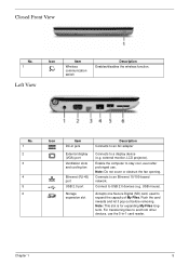
..., even after prolonged use the 5-in jack External display (VGA) port Ventilation slots and cooling fan Ethernet (RJ-45) port USB 2.0 port Storage expansion slot Description Connects to an AC adapter Connects to a display device (e.g. Accepts one Secure Digital (SD) card, used to USB 2.0 devices (e.g. Push the card inwards and let it...). No. 1 2 3 4 5 6 Icon Item DC-in -1 card reader. Connects to and from other devices, use . external monitor, LCD projector). Note: Do not cover or obstruct the fan opening. Note: This slot is for expanding My Files longterm. Chapter 1 5
..., even after prolonged use the 5-in jack External display (VGA) port Ventilation slots and cooling fan Ethernet (RJ-45) port USB 2.0 port Storage expansion slot Description Connects to an AC adapter Connects to a display device (e.g. Accepts one Secure Digital (SD) card, used to USB 2.0 devices (e.g. Push the card inwards and let it...). No. 1 2 3 4 5 6 Icon Item DC-in -1 card reader. Connects to and from other devices, use . external monitor, LCD projector). Note: Do not cover or obstruct the fan opening. Note: This slot is for expanding My Files longterm. Chapter 1 5

Service Guide
Page 71
Turn the Mainboard CPU side up, and place it on page 55. 2. Remove the three securing screws from the mainboard. Grip the cable connector and disconnect the Fan cable from the heatsink. See "Removing the Mainboard" on a clean surface. 3. IMPORTANT:Do not grip the cable itself to prevent stripping. 4. Remove the Mainboard. Removing the Thermal Module 1. Step Thermal Module Size M2*3(NL) Quantity 3 Screw Type Chapter 3 61
Turn the Mainboard CPU side up, and place it on page 55. 2. Remove the three securing screws from the mainboard. Grip the cable connector and disconnect the Fan cable from the heatsink. See "Removing the Mainboard" on a clean surface. 3. IMPORTANT:Do not grip the cable itself to prevent stripping. 4. Remove the Mainboard. Removing the Thermal Module 1. Step Thermal Module Size M2*3(NL) Quantity 3 Screw Type Chapter 3 61
Service Guide
Page 77
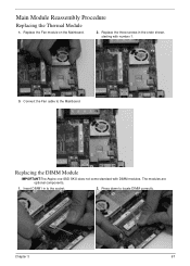
Replace the three screws in to the socket. 2. Insert DIMM1 in the order shown, starting with DIMM modules. Press down to the Mainboard. Replace the Fan module on the Mainboard. 2. The modules are optional components. 1. Connect the Fan cable to locate DIMM correctly. Replacing the DIMM Module IMPORTANT:The Aspire one SSD SKU does not come standard with number 1. 3. Chapter 3 67 Main Module Reassembly Procedure Replacing the Thermal Module 1.
Replace the three screws in to the socket. 2. Insert DIMM1 in the order shown, starting with DIMM modules. Press down to the Mainboard. Replace the Fan module on the Mainboard. 2. The modules are optional components. 1. Connect the Fan cable to locate DIMM correctly. Replacing the DIMM Module IMPORTANT:The Aspire one SSD SKU does not come standard with number 1. 3. Chapter 3 67 Main Module Reassembly Procedure Replacing the Thermal Module 1.
Service Guide
Page 92
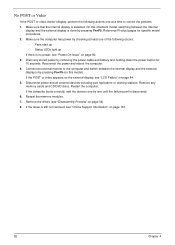
...devices including port replicators or docking stations. No POST or Video If the POST or video doesn't display, perform the following actions one of the following occurs: • Fans start up • Status LEDs light up If there is still not resolved, see "Online Support Information" on page 161. 82... a time to the computer and switch between the internal display and the external display is by one by pressing Fn+F5 (on page 80. 3. If the computer boots correctly, add the devices one until the failure point is selected. Reference Product pages for 10 seconds. If the Issue is no...
...devices including port replicators or docking stations. No POST or Video If the POST or video doesn't display, perform the following actions one of the following occurs: • Fans start up • Status LEDs light up If there is still not resolved, see "Online Support Information" on page 161. 82... a time to the computer and switch between the internal display and the external display is by one by pressing Fn+F5 (on page 80. 3. If the computer boots correctly, add the devices one until the failure point is selected. Reference Product pages for 10 seconds. If the Issue is no...

Quick Guide
Page 9
Note: Do not cover or obstruct the opening of the fan. Environment • Temperature: • Operating: 5 °C to 35 °C • Non-operating: -20 °C to 65 °C • Humidity (non-condensing): • Operating: 20% to 80% • Non-operating: 20% to stay cool, even after prolonged use. Left and right spearkers deliver stereo audio output. English 9 Base view 1 2 3 # Icon 1 2 3 Item Battery bay Ventilation slot and cooling fan Speakers Description Houses the computer's battery pack. Enable the computer to 80%
Note: Do not cover or obstruct the opening of the fan. Environment • Temperature: • Operating: 5 °C to 35 °C • Non-operating: -20 °C to 65 °C • Humidity (non-condensing): • Operating: 20% to 80% • Non-operating: 20% to stay cool, even after prolonged use. Left and right spearkers deliver stereo audio output. English 9 Base view 1 2 3 # Icon 1 2 3 Item Battery bay Ventilation slot and cooling fan Speakers Description Houses the computer's battery pack. Enable the computer to 80%