
Acer Aspire One 531H Netbook Series User Guide
Page 5
.... Refer all servicing to prolong the lifetime of other controls may cause the battery to replace the power cord set . Do not pierce, open or disassemble the battery. Do not use it in a pressurized container, and do not expose it to temperatures over 60°C (140°F). The full performance of...
.... Refer all servicing to prolong the lifetime of other controls may cause the battery to replace the power cord set . Do not pierce, open or disassemble the battery. Do not use it in a pressurized container, and do not expose it to temperatures over 60°C (140°F). The full performance of...
Acer Aspire One 531H Netbook Series User Guide
Page 6
.... (These look like metal strips on the battery.) This might happen, for its enhancements may also explode if damaged. Use only Acer approved batteries, and recharge your laptop under the following conditions. Battery performance is fully charged. Wireless devices may be reduced if the... will be susceptible to interference from children. Follow local regulations when disposing of small children. Please recycle when possible. Do not disassemble or dispose of them away from the battery, which came bundled with a hot or cold battery may not work temporarily, even...
.... (These look like metal strips on the battery.) This might happen, for its enhancements may also explode if damaged. Use only Acer approved batteries, and recharge your laptop under the following conditions. Battery performance is fully charged. Wireless devices may be reduced if the... will be susceptible to interference from children. Follow local regulations when disposing of small children. Please recycle when possible. Do not disassemble or dispose of them away from the battery, which came bundled with a hot or cold battery may not work temporarily, even...
Aspire One AO531h Service Guide
Page 7
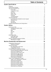
Table of Contents System Specifications 1 Features 1 System Block Diagram 4 Your Acer Notebook tour 5 Front View 5 Closed Front View 6 Left View 6 Right View 7 Bottom View 8 Indicators 9 TouchPad Basics 10 Using the Keyboard 11 Lock Keys and embedded ... 43 Removing the Lower Covers 44 Removing the DIMM Module 45 Removing the WLAN Module 46 Removing the 3G Module 48 Upper Cover Disassembly Process 50 Upper Cover Disassembly Flowchart 50 Removing the Keyboard 51 Removing the Upper Cover 54 Removing the Power Board 58 Removing the Button Board 60 Removing the...
Table of Contents System Specifications 1 Features 1 System Block Diagram 4 Your Acer Notebook tour 5 Front View 5 Closed Front View 6 Left View 6 Right View 7 Bottom View 8 Indicators 9 TouchPad Basics 10 Using the Keyboard 11 Lock Keys and embedded ... 43 Removing the Lower Covers 44 Removing the DIMM Module 45 Removing the WLAN Module 46 Removing the 3G Module 48 Upper Cover Disassembly Process 50 Upper Cover Disassembly Flowchart 50 Removing the Keyboard 51 Removing the Upper Cover 54 Removing the Power Board 58 Removing the Button Board 60 Removing the...
Aspire One AO531h Service Guide
Page 8
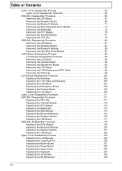
... Module 73 Removing the Mainboard 75 Removing the RTC Battery 76 Removing the Thermal Module 77 Removing the CPU Fan 78 HDD SKU Disassembly Procedure 80 Removing the LED Board 81 Removing the Speaker Module 83 Removing the Bluetooth Module 85 Removing the Hard Disk Drive Module ...87 LCD Module Disassembly Process 89 LCD Module Disassembly Flowchart 89 Removing the LCD Bezel 90 Removing the Camera Board 92 Removing the Microphone Board 93 Removing the LCD Panel ...
... Module 73 Removing the Mainboard 75 Removing the RTC Battery 76 Removing the Thermal Module 77 Removing the CPU Fan 78 HDD SKU Disassembly Procedure 80 Removing the LED Board 81 Removing the Speaker Module 83 Removing the Bluetooth Module 85 Removing the Hard Disk Drive Module ...87 LCD Module Disassembly Process 89 LCD Module Disassembly Flowchart 89 Removing the LCD Bezel 90 Removing the Camera Board 92 Removing the Microphone Board 93 Removing the LCD Panel ...

Aspire One AO531h Service Guide
Page 49
... During the disassembly process, group the screws with the corresponding components to disassemble the notebook computer for the different components vary in the disassembly procedures may ...not represent the final product color or configuration. This chapter contains step-by-step procedures on how to avoid mismatch when putting back the components. Machine Disassembly and Replacement Chapter 3 IMPORTANT: This disassembly procedure represents two separate SKUs for the Aspire one...
... During the disassembly process, group the screws with the corresponding components to disassemble the notebook computer for the different components vary in the disassembly procedures may ...not represent the final product color or configuration. This chapter contains step-by-step procedures on how to avoid mismatch when putting back the components. Machine Disassembly and Replacement Chapter 3 IMPORTANT: This disassembly procedure represents two separate SKUs for the Aspire one...
Aspire One AO531h Service Guide
Page 50
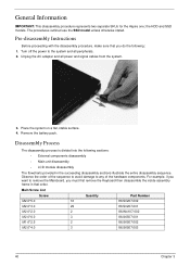
... the system and all power and signal cables from the system. 3. General Information IMPORTANT: This disassembly procedure represents two separate SKUs for the Aspire one; Pre-disassembly Instructions Before proceeding with the disassembly procedure, make sure that order. Disassembly Process The disassembly process is divided into the following : 1. Observe the order of the sequence to avoid damage...
... the system and all power and signal cables from the system. 3. General Information IMPORTANT: This disassembly procedure represents two separate SKUs for the Aspire one; Pre-disassembly Instructions Before proceeding with the disassembly procedure, make sure that order. Disassembly Process The disassembly process is divided into the following : 1. Observe the order of the sequence to avoid damage...
Aspire One AO531h Service Guide
Page 51
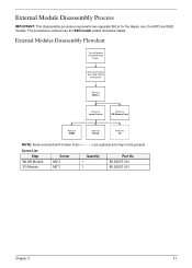
the HDD and SSD models. External Modules Disassembly Flowchart Turn off system and peripherals power Disconnect power and signal cables from system Rem ove Battery Rem ove Lower Covers Rem ove SD Dummy ... be present. Screw List Step WLAN Module 3G Module Screw M2*3 M2*3 Quantity 1 1 Part No. 86.S0207.001 86.S0207.001 Chapter 3 41 External Module Disassembly Process IMPORTANT: This disassembly procedure represents two separate SKUs for the Aspire one; The procedures outlined use the SSD model unless otherwise stated.
the HDD and SSD models. External Modules Disassembly Flowchart Turn off system and peripherals power Disconnect power and signal cables from system Rem ove Battery Rem ove Lower Covers Rem ove SD Dummy ... be present. Screw List Step WLAN Module 3G Module Screw M2*3 M2*3 Quantity 1 1 Part No. 86.S0207.001 86.S0207.001 Chapter 3 41 External Module Disassembly Process IMPORTANT: This disassembly procedure represents two separate SKUs for the Aspire one; The procedures outlined use the SSD model unless otherwise stated.

Aspire One AO531h Service Guide
Page 56
Removing the WLAN Module IMPORTANT: The following disassembly images represent the optional 3G model. See "Removing the Lower Covers" on the WLAN Module. Move the antennas away and remove the single screw on page 44. 2. The 3G module on the left of the images may not be present. 1. Disconnect the antenna cables from the WLAN Module. IMPORTANT: The black cable attaches to the Main terminal and the white (or gray for models without the optional 3G module) cable attaches to the AUX terminal. 3. Step WLAN Module Size M2*3 Quantity 1 Screw Type 46 Chapter 3
Removing the WLAN Module IMPORTANT: The following disassembly images represent the optional 3G model. See "Removing the Lower Covers" on the WLAN Module. Move the antennas away and remove the single screw on page 44. 2. The 3G module on the left of the images may not be present. 1. Disconnect the antenna cables from the WLAN Module. IMPORTANT: The black cable attaches to the Main terminal and the white (or gray for models without the optional 3G module) cable attaches to the AUX terminal. 3. Step WLAN Module Size M2*3 Quantity 1 Screw Type 46 Chapter 3
Aspire One AO531h Service Guide
Page 60
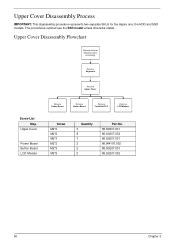
The procedures outlined use the SSD model unless otherwise stated. Upper Cover Disassembly Flowchart Remove External Modules before proceeding Rem ove Keyboard Rem ove Upper Cover Screw List Step Upper Cover Power Board Button Board LCD Module Rem ...*5 Quantity 3 8 7 2 2 2 Part No. 86.S6507.001 86.S0207.002 86.S0207.001 86.W4107.002 86.S0207.001 86.S0207.002 50 Chapter 3 Upper Cover Disassembly Process IMPORTANT: This disassembly procedure represents two separate SKUs for the Aspire one; the HDD and SSD models.
The procedures outlined use the SSD model unless otherwise stated. Upper Cover Disassembly Flowchart Remove External Modules before proceeding Rem ove Keyboard Rem ove Upper Cover Screw List Step Upper Cover Power Board Button Board LCD Module Rem ...*5 Quantity 3 8 7 2 2 2 Part No. 86.S6507.001 86.S0207.002 86.S0207.001 86.W4107.002 86.S0207.001 86.S0207.002 50 Chapter 3 Upper Cover Disassembly Process IMPORTANT: This disassembly procedure represents two separate SKUs for the Aspire one; the HDD and SSD models.

Aspire One AO531h Service Guide
Page 72
See "Removing the Button Board" on the Upper Cover and replace the entire Upper Cover. 1. If the TouchPad malfunctions, follow the disassembly steps to remove the TouchPad on the Aspire one. Open the TouchPad FFC locking latch and remove the FFC as shown. 62 Chapter 3 Removing the TouchPad FFC IMPORTANT: It is not possible to remove any additional components on page 60. 2.
See "Removing the Button Board" on the Upper Cover and replace the entire Upper Cover. 1. If the TouchPad malfunctions, follow the disassembly steps to remove the TouchPad on the Aspire one. Open the TouchPad FFC locking latch and remove the FFC as shown. 62 Chapter 3 Removing the TouchPad FFC IMPORTANT: It is not possible to remove any additional components on page 60. 2.

Aspire One AO531h Service Guide
Page 75
...S6507.002 86.S0207.001 86.S0207.001 86.S0207.001 86.S0207.001 86.S0207.001 86.S0207.001 Chapter 3 65 Lower Cover Disassembly Flowchart Remove External Modules before proceeding Rem ove LED Board Rem ove Speakers Rem ove SSD Rem ove HDD Rem ove Bluetooth Rem ove ...Mainboard Rem ove Thermal Module Rem ove CPU Fan NOTE: Items enclosed with broken lines (- - - -) are identical. Lower Cover Disassembly Process IMPORTANT: The Lower Cover disassembly procedure is split in to two separate sections for the SSD and HDD models, though the flowchart and other components are optional and...
...S6507.002 86.S0207.001 86.S0207.001 86.S0207.001 86.S0207.001 86.S0207.001 86.S0207.001 Chapter 3 65 Lower Cover Disassembly Flowchart Remove External Modules before proceeding Rem ove LED Board Rem ove Speakers Rem ove SSD Rem ove HDD Rem ove Bluetooth Rem ove ...Mainboard Rem ove Thermal Module Rem ove CPU Fan NOTE: Items enclosed with broken lines (- - - -) are identical. Lower Cover Disassembly Process IMPORTANT: The Lower Cover disassembly procedure is split in to two separate sections for the SSD and HDD models, though the flowchart and other components are optional and...

Aspire One AO531h Service Guide
Page 76
SSD SKU Disassembly Procedure The SSD SKU Lower Assembly appears as shown after removal of the Upper Cover and LCD Module. 66 Chapter 3
SSD SKU Disassembly Procedure The SSD SKU Lower Assembly appears as shown after removal of the Upper Cover and LCD Module. 66 Chapter 3

Aspire One AO531h Service Guide
Page 90
HDD SKU Disassembly Procedure The HDD SKU Lower Assembly appears as shown after removal of the Upper Cover and LCD Module. 80 Chapter 3
HDD SKU Disassembly Procedure The HDD SKU Lower Assembly appears as shown after removal of the Upper Cover and LCD Module. 80 Chapter 3

Aspire One AO531h Service Guide
Page 99
If 3G is not supported, only the WLAN antennas (white and black) need to be removed. LCD Module Disassembly Process IMPORTANT: Cable paths and positioning may not represent the actual model. During the removal and replacement of components, ensure all available cable... are four antenna cables (white, black, yellow, and blue) addressed during the procedure. NOTE: These disassembly procedures feature the 3G model only, therefore there are replaced in the same position. LCD Module Disassembly Flowchart Remove LCD Panel from Main Unit before proceeding Rem ove LCD Bezel Rem ove Microphone Board...
If 3G is not supported, only the WLAN antennas (white and black) need to be removed. LCD Module Disassembly Process IMPORTANT: Cable paths and positioning may not represent the actual model. During the removal and replacement of components, ensure all available cable... are four antenna cables (white, black, yellow, and blue) addressed during the procedure. NOTE: These disassembly procedures feature the 3G model only, therefore there are replaced in the same position. LCD Module Disassembly Flowchart Remove LCD Panel from Main Unit before proceeding Rem ove LCD Bezel Rem ove Microphone Board...

Aspire One AO531h Service Guide
Page 108
... in place. 98 Chapter 3 If 3G is not supported, only the WLAN antennas (white and black) need to be removed. 1. Removing the Antennas NOTE: These disassembly procedures feature the 3G model only, therefore there are removed. • A-yellow 3G Antenna cable • B-combined blue 3G Antenna cable, white and black WLAN...
... in place. 98 Chapter 3 If 3G is not supported, only the WLAN antennas (white and black) need to be removed. 1. Removing the Antennas NOTE: These disassembly procedures feature the 3G model only, therefore there are removed. • A-yellow 3G Antenna cable • B-combined blue 3G Antenna cable, white and black WLAN...
Aspire One AO531h Service Guide
Page 152
... no red Xs or yellow exclamation marks. • There are no device conflicts. • No hardware is more than one at a time to its highest level. See "Disassembly Process" on page 40. 5. See "Disassembly Process" on page 40. 4. c. Click Apply and check the display. Run the Windows Memory Diagnostic from the operating system...
... no red Xs or yellow exclamation marks. • There are no device conflicts. • No hardware is more than one at a time to its highest level. See "Disassembly Process" on page 40. 5. See "Disassembly Process" on page 40. 4. c. Click Apply and check the display. Run the Windows Memory Diagnostic from the operating system...
Aspire One AO531h Service Guide
Page 157
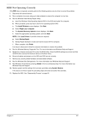
... a known good date using up-to-date software to resolve the problem. 4. Select Repair your computer. Run the Windows Memory Diagnostic Tool. See "Disassembly Process" on the Boot menu. 6. Chapter 4 147 i. Remove any key to start to correct the problem. 1. d. When complete, click Finish.... HDD Not Operating Correctly If the HDD does not operate correctly, perform the following actions one at a time to the operating system DVD. Disconnect all cables and jumpers on the HDD and ODD are set as the first ...
... a known good date using up-to-date software to resolve the problem. 4. Select Repair your computer. Run the Windows Memory Diagnostic Tool. See "Disassembly Process" on the Boot menu. 6. Chapter 4 147 i. Remove any key to start to correct the problem. 1. d. When complete, click Finish.... HDD Not Operating Correctly If the HDD does not operate correctly, perform the following actions one at a time to the operating system DVD. Disconnect all cables and jumpers on the HDD and ODD are set as the first ...

Aspire One AO531h Service Guide
Page 205
... caps lock on indicator 9 Common Problems 140 CPU Fan Replacing 111 D DIMM Module Removing 45 Replacing 136 Display 4 display hotkeys 13 E Euro 14 External Module Disassembly Flowchart 41 F Features 1 FLASH Utility 29 Flash Utility 29 FPC Cable Removing 95 FRU (Field Replaceable Unit) List 163 H HDD Module Removing 73, 87 Replacing...
... caps lock on indicator 9 Common Problems 140 CPU Fan Replacing 111 D DIMM Module Removing 45 Replacing 136 Display 4 display hotkeys 13 E Euro 14 External Module Disassembly Flowchart 41 F Features 1 FLASH Utility 29 Flash Utility 29 FPC Cable Removing 95 FRU (Field Replaceable Unit) List 163 H HDD Module Removing 73, 87 Replacing...

Aspire One AO531h Service Guide
Page 206
... Removing 90 Replacing 109 LCD Brackets Removing 95 Replacing 105 LCD Cable Replacing 105 LCD Failure 143 LCD Module Removing 63 Replacing 124 LCD Module Disassembly Flowchart 89 LCD Module Reassembly 102 LCD Panel Removing 94 Replacing 107 LED Board Removing (HDD) 81 Removing (SSD) 67 Replacing (HDD) 122 Replacing (SSD...
... Removing 90 Replacing 109 LCD Brackets Removing 95 Replacing 105 LCD Cable Replacing 105 LCD Failure 143 LCD Module Removing 63 Replacing 124 LCD Module Disassembly Flowchart 89 LCD Module Reassembly 102 LCD Panel Removing 94 Replacing 107 LED Board Removing (HDD) 81 Removing (SSD) 67 Replacing (HDD) 122 Replacing (SSD...

Aspire One AO531h Service Guide
Page 207
Replacing (SSD) 116 speakers hotkey 13 SSD Module Replacing 114 SSD SKU Disassembly Procedure 66 SSD SKU Reassembly Procedure 111 System Block Diagram 4 T Test Compatible Components 183 Thermal Module Removing 77 Replacing 112 Top 159 Touch Pad hotkey ... 149 Power Button 148 Power On 140 Touch Pad 144 USB 148 WLAN 149 U Undetermined Problems 150 Upper Cover Removing 54 Replacing 130 Upper Cover Disassembly Flowchart 50 Upper Cover Reassembly Process 124 USB Failure (Rightside) 148 utility BIOS 21-29 V volume hotkeys 13 W Windows 2000 Environment Test 184 Wireless Function...
Replacing (SSD) 116 speakers hotkey 13 SSD Module Replacing 114 SSD SKU Disassembly Procedure 66 SSD SKU Reassembly Procedure 111 System Block Diagram 4 T Test Compatible Components 183 Thermal Module Removing 77 Replacing 112 Top 159 Touch Pad hotkey ... 149 Power Button 148 Power On 140 Touch Pad 144 USB 148 WLAN 149 U Undetermined Problems 150 Upper Cover Removing 54 Replacing 130 Upper Cover Disassembly Flowchart 50 Upper Cover Reassembly Process 124 USB Failure (Rightside) 148 utility BIOS 21-29 V volume hotkeys 13 W Windows 2000 Environment Test 184 Wireless Function...


