

Altos R710 Service Guide
Page 7
... Menu 30 Advanced Chipset Control 31 PCI Configuration 32 PCI Device, Embedded Devices 33 I/O Device / Peripheral Configuration 36 Memory Configuration 40 Security 41 Server 43 System Management 45 Serial Console Redirection 46 Event Log Configuration 50 Boot 51 Boot Device Priority 52 Hard Drive 54 Removable Devices 55 Exit 56 Fault Resilient Booting 59 Chapter 3 Machine Disassembly and Replacement 60 Disassembly FlowChart 61 General Information 62 Before You Begin 62 Opening the Housing Panels 63 Removing the cover 63 Removing the Riser Card 64 Removing...
... Menu 30 Advanced Chipset Control 31 PCI Configuration 32 PCI Device, Embedded Devices 33 I/O Device / Peripheral Configuration 36 Memory Configuration 40 Security 41 Server 43 System Management 45 Serial Console Redirection 46 Event Log Configuration 50 Boot 51 Boot Device Priority 52 Hard Drive 54 Removable Devices 55 Exit 56 Fault Resilient Booting 59 Chapter 3 Machine Disassembly and Replacement 60 Disassembly FlowChart 61 General Information 62 Before You Begin 62 Opening the Housing Panels 63 Removing the cover 63 Removing the Riser Card 64 Removing...

Altos R710 Service Guide
Page 8
...a Hard Drive 65 Removing the CD-ROM and FDD module 66 Removing Power Supply Moduel 67 Removing the Power Supply Cage 68 Removing the Fan Module 69 Removing the DIMM Module 69 Removing the Heatsink 70 Removing the CPU 70 Removing the Retention Module 70 Removing the Backplane Board 71 Removing the Front Panel Board 71 Removing the Mainboard 71 Chapter 4 Troubleshooting 72 POST Error Codes and Messages 73 Standard POST Error Messages and Codes 73 Extended POST Error Messages and Codes 74 BIOS Recovery Beep Codes 75 Bootblock Error Beep Codes 75 Chapter 5 Jumper and Connector...
...a Hard Drive 65 Removing the CD-ROM and FDD module 66 Removing Power Supply Moduel 67 Removing the Power Supply Cage 68 Removing the Fan Module 69 Removing the DIMM Module 69 Removing the Heatsink 70 Removing the CPU 70 Removing the Retention Module 70 Removing the Backplane Board 71 Removing the Front Panel Board 71 Removing the Mainboard 71 Chapter 4 Troubleshooting 72 POST Error Codes and Messages 73 Standard POST Error Messages and Codes 73 Extended POST Error Messages and Codes 74 BIOS Recovery Beep Codes 75 Bootblock Error Beep Codes 75 Chapter 5 Jumper and Connector...

Altos R710 Service Guide
Page 11
... system fans in default configuration T Two non-redundant fans in each power supply Server Management/Diagnositcs T On-board Platform Instrumentation using the National Semiconductor PC87431M miniBasedboard Management Controller (mBMC) (Default) T Support for optional Intelligent Management Module-Prefessional Edition T Support for Acer® Altos Server Management 6.x T Light-Guided Diagnostics on all field replaceable units (FRUs) Dimensions T 3.455 inches high T 16.930 inches wide T 26.457 inches deep T 60 pounds Hard Drives T Up to five fixed or hot-swap SATA or SCSI drives T Drive...
... system fans in default configuration T Two non-redundant fans in each power supply Server Management/Diagnositcs T On-board Platform Instrumentation using the National Semiconductor PC87431M miniBasedboard Management Controller (mBMC) (Default) T Support for optional Intelligent Management Module-Prefessional Edition T Support for Acer® Altos Server Management 6.x T Light-Guided Diagnostics on all field replaceable units (FRUs) Dimensions T 3.455 inches high T 16.930 inches wide T 26.457 inches deep T 60 pounds Hard Drives T Up to five fixed or hot-swap SATA or SCSI drives T Drive...

Altos R710 Service Guide
Page 19
... Blinking green light indicates network activity. Blinking green indicates the system is visible from the rear of a rack of the chassis and allows you to which it . Front Panel LED and Buttons Item A B C D E F Description Power Button LAN #2 Activity LED LAN #1 Activity LED Power LED System Status LED Hard Drive Activity Item G H I J K L Description System ID LED System ID Button System Reset Button USB connector Recessed NMI Button (Tool Required) VGA connector Control Button Functions Item Power/Sleep button Reset button ID button NMI button Description Toggles the system power...
... Blinking green light indicates network activity. Blinking green indicates the system is visible from the rear of a rack of the chassis and allows you to which it . Front Panel LED and Buttons Item A B C D E F Description Power Button LAN #2 Activity LED LAN #1 Activity LED Power LED System Status LED Hard Drive Activity Item G H I J K L Description System ID LED System ID Button System Reset Button USB connector Recessed NMI Button (Tool Required) VGA connector Control Button Functions Item Power/Sleep button Reset button ID button NMI button Description Toggles the system power...

Altos R710 Service Guide
Page 20
... blinking green light indicates hard disk drive activity (SCSI or SATA). No light indicates no hard disk drive activity. LED Indicator Status Item Description No light indicates the power is off System Identification LED Solid blue indicates system identification is active No light indicates system identification is in Card Slots Power Supply Modules (1+1 Configuration Shown) PS2 Keyboard and Mouse Ports RJ45 Serial B port LAN #1 Connector LAN #2 Connector Optional DB9 Serial A port Cut out Videon Connector USB #1 Connector USB #2 Connector Diagnostic POST code LEDs Management NIC...
... blinking green light indicates hard disk drive activity (SCSI or SATA). No light indicates no hard disk drive activity. LED Indicator Status Item Description No light indicates the power is off System Identification LED Solid blue indicates system identification is active No light indicates system identification is in Card Slots Power Supply Modules (1+1 Configuration Shown) PS2 Keyboard and Mouse Ports RJ45 Serial B port LAN #1 Connector LAN #2 Connector Optional DB9 Serial A port Cut out Videon Connector USB #1 Connector USB #2 Connector Diagnostic POST code LEDs Management NIC...

Altos R710 Service Guide
Page 35
... button while still pressing the reset button. Using the control panel, the user can send a specific OEM command to the Sahalee BMC to issue a "reset system configuration" request. If a pick list is capable of pointing devices. Chapter 2 26 Configuration Reset Setting the Clear CMOS jumper (board location J1H4) produces a "reset system configuration" request. When a request is rebooted. The Intel Management Module, when installed, provides a software method to indicate the request. Changes affected by using the F2 key. Software can hold the reset button for console...
... button while still pressing the reset button. Using the control panel, the user can send a specific OEM command to the Sahalee BMC to issue a "reset system configuration" request. If a pick list is capable of pointing devices. Chapter 2 26 Configuration Reset Setting the Clear CMOS jumper (board location J1H4) produces a "reset system configuration" request. When a request is rebooted. The Intel Management Module, when installed, provides a software method to indicate the request. Changes affected by using the F2 key. Software can hold the reset button for console...

Altos R710 Service Guide
Page 50
... USB Support Port 60/64 Emulation USB 2.0 Controller Disabled Enabled Disabled/ Keyboard only/ Auto/Keyboard and Mouse Disabled/ Enabled Disabled/ Enabled Enables USB HOST controllers Enables support for non-USB aware OSes. This should be disabled until booting an OS. Enables I/O port 60/64h emulation support. When set to disabled, other USB options are connected. If disabled, USB Legacy Support will not be enabled for the complete USB keyboard legacy support for legacy USB. N/A Description List of USB devices detected by BIOS. AUTO option disables legacy support if no USB...
... USB Support Port 60/64 Emulation USB 2.0 Controller Disabled Enabled Disabled/ Keyboard only/ Auto/Keyboard and Mouse Disabled/ Enabled Disabled/ Enabled Enables USB HOST controllers Enables support for non-USB aware OSes. This should be disabled until booting an OS. Enables I/O port 60/64h emulation support. When set to disabled, other USB options are connected. If disabled, USB Legacy Support will not be enabled for the complete USB keyboard legacy support for legacy USB. N/A Description List of USB devices detected by BIOS. AUTO option disables legacy support if no USB...

Altos R710 Service Guide
Page 53
... Slot 1 Option ROM Slot 2 Option ROM Slot 3 Option ROM Before changing modes, back up array data and delete existing arrays, if any. Grayed out if device is disabled. Visable only when installed riser supports this slot. Otherwise, loss of Onboard Video is set to each device. Visable only when installed riser supports this slot. After OS installation with a selected SCSI RAID mode, only change this mode selection if prepared to use as the primary boot device. PCI Configuration Sub-menu Selections Feature PCI Configuration Onboard Video Dual Monitor Video...
... Slot 1 Option ROM Slot 2 Option ROM Slot 3 Option ROM Before changing modes, back up array data and delete existing arrays, if any. Grayed out if device is disabled. Visable only when installed riser supports this slot. Otherwise, loss of Onboard Video is set to each device. Visable only when installed riser supports this slot. After OS installation with a selected SCSI RAID mode, only change this mode selection if prepared to use as the primary boot device. PCI Configuration Sub-menu Selections Feature PCI Configuration Onboard Video Dual Monitor Video...

Altos R710 Service Guide
Page 99
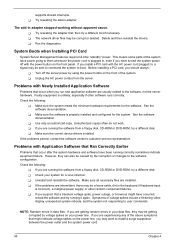
... configuration settings made in the proper location and not touching any components, causing a potential short? Check the tested memory, and chassis lists, as well as the supported hardware and operating system list. T Are the power supplies plugged in boards and peripheral devices correct? Chapter 4 90 T Is the operating system properly loaded? T Are all cables correctly connected and secured? Hardware failure is it properly formatted or configured? T Are all add-in PCI boards fully seated in boards...
... configuration settings made in the proper location and not touching any components, causing a potential short? Check the tested memory, and chassis lists, as well as the supported hardware and operating system list. T Are the power supplies plugged in boards and peripheral devices correct? Chapter 4 90 T Is the operating system properly loaded? T Are all cables correctly connected and secured? Hardware failure is it properly formatted or configured? T Are all add-in PCI boards fully seated in boards...

Altos R710 Service Guide
Page 103
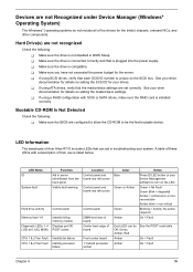
... Light Check the following : T Are the CD-ROM/DVD-ROM drive's power and signal cables properly installed? If so, the signal cable may be plugged in diskette controller, make sure that "Onboard Floppy" is set to "Enabled." If you specify the correct frame type in adapter was installed. T Make sure you will need a crossover cable. Problems with other adapter supports shared interrupts. T Are all relevant switches and jumpers on changing interrupts. For these drivers...
... Light Check the following : T Are the CD-ROM/DVD-ROM drive's power and signal cables properly installed? If so, the signal cable may be plugged in diskette controller, make sure that "Onboard Floppy" is set to "Enabled." If you specify the correct frame type in adapter was installed. T Make sure you will need a crossover cable. Problems with other adapter supports shared interrupts. T Are all relevant switches and jumpers on changing interrupts. For these drivers...
Altos R710 Service Guide
Page 104
... slot if necessary. T Unplug the AC power cord(s) from a floppy disk, CD-ROM or DVD-ROM, try running correctly sometimes indicate equipment failure. T Use only an authorized copy. T If you install a PCI card with Application Software that Ran Correctly Earlier Problems that occur after the system hardware and software have power going to user commands. However, they may be corrupt or deleted. T Uninstall and reinstall the software. then try a different disk. Check...
... slot if necessary. T Unplug the AC power cord(s) from a floppy disk, CD-ROM or DVD-ROM, try running correctly sometimes indicate equipment failure. T Use only an authorized copy. T If you install a PCI card with Application Software that Ran Correctly Earlier Problems that occur after the system hardware and software have power going to user commands. However, they may be corrupt or deleted. T Uninstall and reinstall the software. then try a different disk. Check...
Altos R710 Service Guide
Page 105
... Acer Altos R710 includes LEDs that each SCSI ID number is unique on setting the SCSI ID for your system. LED Name ID System fault Hard drive activity Memory fault 1-6 Diagnostic LEDs. 1-4 LSB, bit1, bit2, MSB) CPU 1 & 2 Fan Fault CPU 1 & 2 Fan Fault Function Aid in server identificaton from the back panel Visible fault warning Control panel Identify failing memory module Displays port 80 POST codes Identify fan failure Identify processor failure Location Control panel and board rear left corner Control panel and board rear left corner Control panel DIMM end rear of board Center back edge...
... Acer Altos R710 includes LEDs that each SCSI ID number is unique on setting the SCSI ID for your system. LED Name ID System fault Hard drive activity Memory fault 1-6 Diagnostic LEDs. 1-4 LSB, bit1, bit2, MSB) CPU 1 & 2 Fan Fault CPU 1 & 2 Fan Fault Function Aid in server identificaton from the back panel Visible fault warning Control panel Identify failing memory module Displays port 80 POST codes Identify fan failure Identify processor failure Location Control panel and board rear left corner Control panel and board rear left corner Control panel DIMM end rear of board Center back edge...
Altos R710 Service Guide
Page 107
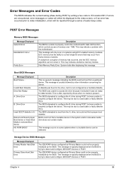
... message indicating the BIOS could not boot from the A: drive, but was unable to I/O location 80H. BIOS could not be detected. Storage Device BIOS Messages Message Displayed Primary Master Hard Disk Error Primary Slave Hard Disk Error Description The IDE/ATAPI device configured as Primary Master could not find a proper boot diskette. Error Messages and Error Codes The BIOS indicates the current testing phase during POST by writing a hex code to access the drive because it indicated it was not ready for data transfer...
... message indicating the BIOS could not boot from the A: drive, but was unable to I/O location 80H. BIOS could not be detected. Storage Device BIOS Messages Message Displayed Primary Master Hard Disk Error Primary Slave Hard Disk Error Description The IDE/ATAPI device configured as Primary Master could not find a proper boot diskette. Error Messages and Error Codes The BIOS indicates the current testing phase during POST by writing a hex code to access the drive because it indicated it was not ready for data transfer...

Altos R710 Service Guide
Page 109
...to replace the hard disk. failure messages may indicate the need to replace the hard disk. VIRUS: Continue (Y/N)? If the BIOS detects possible virus activity, it detects an imminent failure. System Configuration BIOS Messages Message Displayed DMA-2 Error DMA Controller Error Checking NVRAM..Update Failed Description Error initializing secondary DMA controller. This message appears when the FLASH part is write-protected or if there is a fatal error, often indication a problem with system hardware. Storage Device BIOS Messages Message Displayed Description 5th Master Drive...
...to replace the hard disk. failure messages may indicate the need to replace the hard disk. VIRUS: Continue (Y/N)? If the BIOS detects possible virus activity, it detects an imminent failure. System Configuration BIOS Messages Message Displayed DMA-2 Error DMA Controller Error Checking NVRAM..Update Failed Description Error initializing secondary DMA controller. This message appears when the FLASH part is write-protected or if there is a fatal error, often indication a problem with system hardware. Storage Device BIOS Messages Message Displayed Description 5th Master Drive...

Altos R710 Service Guide
Page 110
... Interrupt Controller. CMOS Battery is not detected. 101 Chapter 4 This error can typically be resolved by using AMIBIOS Setup. PS2 Mouse support is enabled in the BIOS setup but the device is not retaining its data due to malfunction. A PCI adapter generated an I /O resource conflict when configured by BIOS POST. This may indicate a problem with system hardware. This message usually indicates that the CMOS is not detected. CMOS contents failed the Checksum check. Indicates that the CMOS data...
... Interrupt Controller. CMOS Battery is not detected. 101 Chapter 4 This error can typically be resolved by using AMIBIOS Setup. PS2 Mouse support is enabled in the BIOS setup but the device is not retaining its data due to malfunction. A PCI adapter generated an I /O resource conflict when configured by BIOS POST. This may indicate a problem with system hardware. This message usually indicates that the CMOS is not detected. CMOS contents failed the Checksum check. Indicates that the CMOS data...

Altos R710 Service Guide
Page 112
...Error Message CMOS Settings Wrong CMOS Checksum Bad Unlock Keyboard PS2 Keyboard not found KBC BAT Test failed CMOS memory size different RAM R/W test failed A: Drive Error B: Drive Error Floppy Controller Failure CMOS time not set PS2 Mouse not found Refresh timer test failed Display memory test failed CMOS Display Type Wrong ~ Pressed DMA Controller Error DMA-1 Error DMA-2 Error Unknown BIOS error. ATAPI Incompatible Primary Slave Drive - Status BAD, Backup and Replace Password check failed Thermal Trip Failure Insufficient Memory to Shadow PCI ROM BSP Processor failed BIST Processor...
...Error Message CMOS Settings Wrong CMOS Checksum Bad Unlock Keyboard PS2 Keyboard not found KBC BAT Test failed CMOS memory size different RAM R/W test failed A: Drive Error B: Drive Error Floppy Controller Failure CMOS time not set PS2 Mouse not found Refresh timer test failed Display memory test failed CMOS Display Type Wrong ~ Pressed DMA Controller Error DMA-1 Error DMA-2 Error Unknown BIOS error. ATAPI Incompatible Primary Slave Drive - Status BAD, Backup and Replace Password check failed Thermal Trip Failure Insufficient Memory to Shadow PCI ROM BSP Processor failed BIST Processor...

Altos R710 Service Guide
Page 113
..., Processor Model are different Processor speeds mismatched CMOS Cleared By Jumper Password cleared by this USB Host Controller!!! It requires 64bit data support in Runtime area!! Processor 01 Internal error (IERR) Processor 02 Internal error (IERR) Processor 01 Thermal Trip error Processor 02 Thermal Trip error Processor 01 disabled Processor 02 disabled Processor 01 failed FRB-3 timer Processor 02 failed FRB-3 timer Processor 01 failed initialization on last boot Processor 02 failed initialization on last boot OS boot watchdog timer failure BaseBoard Management Controller failed Self Test...
..., Processor Model are different Processor speeds mismatched CMOS Cleared By Jumper Password cleared by this USB Host Controller!!! It requires 64bit data support in Runtime area!! Processor 01 Internal error (IERR) Processor 02 Internal error (IERR) Processor 01 Thermal Trip error Processor 02 Thermal Trip error Processor 01 disabled Processor 02 disabled Processor 01 failed FRB-3 timer Processor 02 failed FRB-3 timer Processor 01 failed initialization on last boot Processor 02 failed initialization on last boot OS boot watchdog timer failure BaseBoard Management Controller failed Self Test...

Altos R710 Service Guide
Page 115
... command failed No Flash EPROM detected Floppy controller failure Boot Block BIOS checksum error Flash Erase error Chapter 4 106 Prior to system video initialization, the BIOS uses these beep codes to protected mode) General exception error (processor exception error) Display memory error (system video adapter) ROM checksum error CMOS shutdown register read/write error Cache memory test failed Troubleshooting BIOS Beep Codes Number of diskette in base memory (first 64KB block) Base memory read / write test error Motherboard timer not operational Processor error 8042 Gate A20 test error...
... command failed No Flash EPROM detected Floppy controller failure Boot Block BIOS checksum error Flash Erase error Chapter 4 106 Prior to system video initialization, the BIOS uses these beep codes to protected mode) General exception error (processor exception error) Display memory error (system video adapter) ROM checksum error CMOS shutdown register read/write error Cache memory test failed Troubleshooting BIOS Beep Codes Number of diskette in base memory (first 64KB block) Base memory read / write test error Motherboard timer not operational Processor error 8042 Gate A20 test error...

Altos R710 Service Guide
Page 116
... the user of errors. . No processor is installed or the CPU 1 socket is active. Before checking for Multi-Disk Recovery BMC Generated Beep Codes (Professional/Advanced only) The Sahalee BMC generates beep codes upon detection of the failure conditions listed in a series of beeps being issued known as "beep codes". Reseat or replace the failed processor. These beeps have beep codes. For example, some Intel® RAID cards have a code that identifies system or PCI card events. DC power unexpectedly lost. In a two-processor...
... the user of errors. . No processor is installed or the CPU 1 socket is active. Before checking for Multi-Disk Recovery BMC Generated Beep Codes (Professional/Advanced only) The Sahalee BMC generates beep codes upon detection of the failure conditions listed in a series of beeps being issued known as "beep codes". Reseat or replace the failed processor. These beeps have beep codes. For example, some Intel® RAID cards have a code that identifies system or PCI card events. DC power unexpectedly lost. In a two-processor...

Altos R710 Service Guide
Page 118
... Power Connector 18 MCH - A bootable Recovery BIOS floppy disk must be in BIOS Setup Password Clr Prtect - Pins 1-2 (Default) Enabled - Configures Pin 7 of Fore to lower bank - Jumper across Pins 1-3 DSR Select - Reference ID Name J1H2 BIOS Recovery Boot J1H3 Password Clear J1H4 J1A4 J7A1 CMOS Clear Rolling BIOS Configuration Seriall B Configuration Description Settings Forces the system to boot Normal Operation - Pins 2-3 Clears Administrator and User pasword passwords as set in Drive A for this operation. Pins 2-3 Sets the BIOS flash device to boot into BIOS Recovery...
... Power Connector 18 MCH - A bootable Recovery BIOS floppy disk must be in BIOS Setup Password Clr Prtect - Pins 1-2 (Default) Enabled - Configures Pin 7 of Fore to lower bank - Jumper across Pins 1-3 DSR Select - Reference ID Name J1H2 BIOS Recovery Boot J1H3 Password Clear J1H4 J1A4 J7A1 CMOS Clear Rolling BIOS Configuration Seriall B Configuration Description Settings Forces the system to boot Normal Operation - Pins 2-3 Clears Administrator and User pasword passwords as set in Drive A for this operation. Pins 2-3 Sets the BIOS flash device to boot into BIOS Recovery...


