
AL506 Monitor Service Guide
Page 1
... 1 Service Tools ...13 5. Front View ...3 2-2. Remove Bezel ...22 6-5. Definition of the Connector Pin of Computer 43 8-2. Programs: ...48 9-2. Glossary...54 Method for LCD Monitor Testing after Servicing 43 8-1. Specification ...45 8-5. Troubleshooting Analysis...14 6.Level 1Service Items--MonitorAssembly and Disassembly 19 6-1. Install BIOS Software (Simply way to ROM) & kit 48 9-4. Remove AD PCBA ...29 6-8. Remove Stand Bottom ...20 6-2. Test Method Without Connection of Signal Cable 44 8-4. System Block Diagram ...5 2-4. Remove FFC...
... 1 Service Tools ...13 5. Front View ...3 2-2. Remove Bezel ...22 6-5. Definition of the Connector Pin of Computer 43 8-2. Programs: ...48 9-2. Glossary...54 Method for LCD Monitor Testing after Servicing 43 8-1. Specification ...45 8-5. Troubleshooting Analysis...14 6.Level 1Service Items--MonitorAssembly and Disassembly 19 6-1. Install BIOS Software (Simply way to ROM) & kit 48 9-4. Remove AD PCBA ...29 6-8. Remove Stand Bottom ...20 6-2. Test Method Without Connection of Signal Cable 44 8-4. System Block Diagram ...5 2-4. Remove FFC...

AL506 Monitor Service Guide
Page 2
ACER Monitor AL506 1. If you are not sure of the type of the monitor include casing and tighten the screw while servicing the monitor to prevent hazard. Turn on power for testing only after complete the assembly of power available, consult your dealer or local power company.. 1-2. The LCD shall be operated from the power supply before cleaning. 1-5. The surface of smell 1-6. Disconnect the monitor from the type...
ACER Monitor AL506 1. If you are not sure of the type of the monitor include casing and tighten the screw while servicing the monitor to prevent hazard. Turn on power for testing only after complete the assembly of power available, consult your dealer or local power company.. 1-2. The LCD shall be operated from the power supply before cleaning. 1-5. The surface of smell 1-6. Disconnect the monitor from the type...
AL506 Monitor Service Guide
Page 3
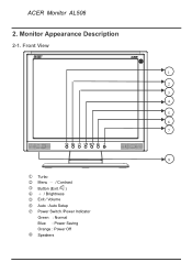
Monitor Appearance Description 2-1. Front View 1 2 3 4 5 6 7 8 1 Turbo 2 Menu - / Contrast 3 Button (Exit / ) 4 + / Brightness 5 Exit / Volume 6 Auto : Auto Setup 7 Power Switch /Power Indicator Green : Normal Blue : Power Saving Orange : Power Off 8 Speakers ACER Monitor AL506 2.
Monitor Appearance Description 2-1. Front View 1 2 3 4 5 6 7 8 1 Turbo 2 Menu - / Contrast 3 Button (Exit / ) 4 + / Brightness 5 Exit / Volume 6 Auto : Auto Setup 7 Power Switch /Power Indicator Green : Normal Blue : Power Saving Orange : Power Off 8 Speakers ACER Monitor AL506 2.
AL506 Monitor Service Guide
Page 8
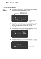
... switched by using the +/-Buttons. Adjustment icon Current horizontal frequency, vertical refresh rate and resolution Select the Menu page that contains the adjustment icon relating to the adjustment you press the Menu Button. Use the +/-Buttons to highlight the desired adjustment icon. V-Position 50 Displayed while Turbo is active Displayed while Mute is active Page no. Press the Menu Button again. Buttons to make . The vertical position of the adjustment being made OSD Menu Screen Operate Explanation Press the Menu Button to change the vertical position...
... switched by using the +/-Buttons. Adjustment icon Current horizontal frequency, vertical refresh rate and resolution Select the Menu page that contains the adjustment icon relating to the adjustment you press the Menu Button. Use the +/-Buttons to highlight the desired adjustment icon. V-Position 50 Displayed while Turbo is active Displayed while Mute is active Page no. Press the Menu Button again. Buttons to make . The vertical position of the adjustment being made OSD Menu Screen Operate Explanation Press the Menu Button to change the vertical position...
AL506 Monitor Service Guide
Page 9
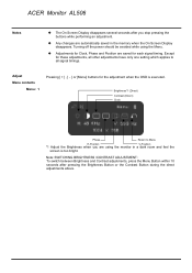
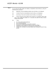
... all signal timings. Any changes are saved for the adjustment when the OSD is too bright. Turning off the power should be avoided while using the monitor in the memory when the On Screen Display disappears. ACER Monitor AL506 Notes The On Screen Display disappears several seconds after pressing the Brightness Button or the Contrast Button during the direct adjustments above. Adjust Menu contents Menu: 1 Pressing or [Menu] buttons for each signal timing. Adjustments for these adjustments, all other adjustments have...
... all signal timings. Any changes are saved for the adjustment when the OSD is too bright. Turning off the power should be avoided while using the monitor in the memory when the On Screen Display disappears. ACER Monitor AL506 Notes The On Screen Display disappears several seconds after pressing the Brightness Button or the Contrast Button during the direct adjustments above. Adjust Menu contents Menu: 1 Pressing or [Menu] buttons for each signal timing. Adjustments for these adjustments, all other adjustments have...

AL506 Monitor Service Guide
Page 10
... signal input is changed . Button to Menu *1 For best results, use the Auto Set-up in reverse numerical order. Note: Auto Set-up Setting: No: The Auto Set-up *1 (Direct) Color Temp. sRGB: User sRGB is an international standard which defines and unifies the difference of less than 1024 × 768. Sharpness Return to change the picture quality in numerical order. Color 2: 7500K; ACER Monitor AL506 Menu: 2 Auto Set-up is not performed when the signal input...
... signal input is changed . Button to Menu *1 For best results, use the Auto Set-up in reverse numerical order. Note: Auto Set-up Setting: No: The Auto Set-up *1 (Direct) Color Temp. sRGB: User sRGB is an international standard which defines and unifies the difference of less than 1024 × 768. Sharpness Return to change the picture quality in numerical order. Color 2: 7500K; ACER Monitor AL506 Menu: 2 Auto Set-up is not performed when the signal input...
AL506 Monitor Service Guide
Page 12
... brightness) Text: Text Mode (Normal) Eco Economy (Brightness of back-light is reduced) Changing to Text Mode when working with text. Auto Set-up: Press the Auto Button when the Menu is off, holding this button for long periods. When OSD menu is not displayed. Change from Picture Mode to a lower brightness mode can skip the Menu pages and display an adjustment scale directly by using the following button operations: Brightness: Press the Brightness Button when the Menu is not displayed. ACER Monitor AL506...
... brightness) Text: Text Mode (Normal) Eco Economy (Brightness of back-light is reduced) Changing to Text Mode when working with text. Auto Set-up: Press the Auto Button when the Menu is off, holding this button for long periods. When OSD menu is not displayed. Change from Picture Mode to a lower brightness mode can skip the Menu pages and display an adjustment scale directly by using the following button operations: Brightness: Press the Brightness Button when the Menu is not displayed. ACER Monitor AL506...

AL506 Monitor Service Guide
Page 14
ACER Monitor AL506 5. Troubleshooting Analysis Defect Mode Failure Analysis Repair Testing Light On Test ※ " Panel Change" Should be Performed to Level 3 Repair stage Abnormal Display Missing Line Bright Dot Dark Dot Backlight Light Leakage Mura Image Sticking Brightness spot Particle Dot Defect No display Check PCB Check Panel Check Panel Check PCB AD/B Change Panel Change Panel Change AD/B Change Inverter Change Check Panel Panel Change Noise A Check PCB Check Panel Next Step AD/B Change Panel Change NG TEST Completed
ACER Monitor AL506 5. Troubleshooting Analysis Defect Mode Failure Analysis Repair Testing Light On Test ※ " Panel Change" Should be Performed to Level 3 Repair stage Abnormal Display Missing Line Bright Dot Dark Dot Backlight Light Leakage Mura Image Sticking Brightness spot Particle Dot Defect No display Check PCB Check Panel Check Panel Check PCB AD/B Change Panel Change Panel Change AD/B Change Inverter Change Check Panel Panel Change Noise A Check PCB Check Panel Next Step AD/B Change Panel Change NG TEST Completed

AL506 Monitor Service Guide
Page 15
ACER Monitor AL506 Defect Mode A Failure Analysis Repair Testing ※ " Panel Change" Should be Performed to Level 3 Repair stage Flicker Check PCB Check OSD AD/B Change Inverter Change Adjust VCOM Gray value display R.G.B display abnormal Check PCB Check Panel Check PCB AD/B Change Panel Change AD/B Change Display Shut Down No signal Check PCB Check Panel Check PCB AD/B Change Inverter Change Panel Change AD/B Change Power on Display abnormal A Check PCB Next Step AD/B Change NG TEST Completed
ACER Monitor AL506 Defect Mode A Failure Analysis Repair Testing ※ " Panel Change" Should be Performed to Level 3 Repair stage Flicker Check PCB Check OSD AD/B Change Inverter Change Adjust VCOM Gray value display R.G.B display abnormal Check PCB Check Panel Check PCB AD/B Change Panel Change AD/B Change Display Shut Down No signal Check PCB Check Panel Check PCB AD/B Change Inverter Change Panel Change AD/B Change Power on Display abnormal A Check PCB Next Step AD/B Change NG TEST Completed

AL506 Monitor Service Guide
Page 16
ACER Monitor AL506 Defect Mode Failure Analysis Repair Testing ※ " Panel Change" Should be Performed to Level 3 Repair stage ON/OF Abnormal No Power Check PCB Check Wire AD/B Change SW/B Change FFC Change LED display abnormal LED Off LED Dark LED Abnormal LED Flicker Check PCB Check Wire AD/B Change SW/B Change FFC Change Abnormal Keyboard Unavailable Check PCB Check Wire Next Step AD/B Change SW/B Change FFC Change NG TEST Completed
ACER Monitor AL506 Defect Mode Failure Analysis Repair Testing ※ " Panel Change" Should be Performed to Level 3 Repair stage ON/OF Abnormal No Power Check PCB Check Wire AD/B Change SW/B Change FFC Change LED display abnormal LED Off LED Dark LED Abnormal LED Flicker Check PCB Check Wire AD/B Change SW/B Change FFC Change Abnormal Keyboard Unavailable Check PCB Check Wire Next Step AD/B Change SW/B Change FFC Change NG TEST Completed

AL506 Monitor Service Guide
Page 17
ACER Monitor AL506 Defect Mode Failure Analysis Repair Testing ※ " Panel Change" Should be Performed at Level 3 Repair stage Abnormal BIOS &OSD Can't Input Can't Read Check PCB AD/B Change Other Abnormal Display Display Shut Down Check PCB Display flicker (tapping ) Check Panel Check PCB Check Panel Next Step AD/B Change Inverter Change Panel Change AD/B Change Inverter Change NG TEST Completed
ACER Monitor AL506 Defect Mode Failure Analysis Repair Testing ※ " Panel Change" Should be Performed at Level 3 Repair stage Abnormal BIOS &OSD Can't Input Can't Read Check PCB AD/B Change Other Abnormal Display Display Shut Down Check PCB Display flicker (tapping ) Check Panel Check PCB Check Panel Next Step AD/B Change Inverter Change Panel Change AD/B Change Inverter Change NG TEST Completed

AL506 Monitor Service Guide
Page 18
ACER Monitor AL506 Defect Mode Failure Analysis Repair Testing ※ " Panel Change" Should be Performed at Level 3 Repair stage Audio Abnormal Sound adjust abnormal No sound Single sound Check PCB Check speaker Check FFC Check PCB AD/B change Speaker change FFC change AD/B change SW/B change TEST Completed
ACER Monitor AL506 Defect Mode Failure Analysis Repair Testing ※ " Panel Change" Should be Performed at Level 3 Repair stage Audio Abnormal Sound adjust abnormal No sound Single sound Check PCB Check speaker Check FFC Check PCB AD/B change Speaker change FFC change AD/B change SW/B change TEST Completed

AL506 Monitor Service Guide
Page 19
ACER Monitor AL506 6. Level 1 Service Items--Monitor Assembly and Disassembly The flow of Monitor assembly and disassembly procedure as below : ※ Must to protect the Polarizar Scratch ※ Must to protect ESD issue 1 Separate Stand 2 Separate Cover 3 Remove Inverter 4 Change Inverter 5 Remove AD PCBA 6 Change AD PCBA 7 Cover Assembly 8 Stand Assembly
ACER Monitor AL506 6. Level 1 Service Items--Monitor Assembly and Disassembly The flow of Monitor assembly and disassembly procedure as below : ※ Must to protect the Polarizar Scratch ※ Must to protect ESD issue 1 Separate Stand 2 Separate Cover 3 Remove Inverter 4 Change Inverter 5 Remove AD PCBA 6 Change AD PCBA 7 Cover Assembly 8 Stand Assembly

AL506 Monitor Service Guide
Page 22
Remove FFC Step 1 - Pull out FFC from connectors at Switch Board and AD PCBA Step 2 - Completed 6-4. Remove Bezel Step 1 - Lift up LCD module and Remove Bezel Step 2 - Completed ACER Monitor AL506 6-3.
Remove FFC Step 1 - Pull out FFC from connectors at Switch Board and AD PCBA Step 2 - Completed 6-4. Remove Bezel Step 1 - Lift up LCD module and Remove Bezel Step 2 - Completed ACER Monitor AL506 6-3.
AL506 Monitor Service Guide
Page 41
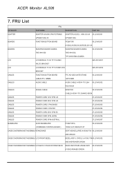
....006 CABLES POWER CORD 3PIN AUSTRIAL 27.L03VG.007 MAINBOARD AL506 MAINBOARD PCBA FOR A 55.L03VG.003 ( FIRMWARE CONTROL BOARD ) 150X2-S,X7,RIGID,201-07 CASE/COVER/BRACKET/ASSEMBLYSTAND BASE SEAT ASSY(ELLIPSE) A150X2-T04 60.L03VG.001 ABS ORIGIN CASE/COVER/BRACKET/ASSEMBLYLCD FRONT BEZEL BEZEL ASSY ( CIRCLE ) A15X2-T04 60.L03VG.002 ABS W/SPEAKER ORIGIN CASE/COVER/BRACKET/ASSEMBLYLCD BACK COVER W/STAND...
....006 CABLES POWER CORD 3PIN AUSTRIAL 27.L03VG.007 MAINBOARD AL506 MAINBOARD PCBA FOR A 55.L03VG.003 ( FIRMWARE CONTROL BOARD ) 150X2-S,X7,RIGID,201-07 CASE/COVER/BRACKET/ASSEMBLYSTAND BASE SEAT ASSY(ELLIPSE) A150X2-T04 60.L03VG.001 ABS ORIGIN CASE/COVER/BRACKET/ASSEMBLYLCD FRONT BEZEL BEZEL ASSY ( CIRCLE ) A15X2-T04 60.L03VG.002 ABS W/SPEAKER ORIGIN CASE/COVER/BRACKET/ASSEMBLYLCD BACK COVER W/STAND...

AL506 Monitor Service Guide
Page 42
... version. ACER Monitor AL506 CASE/COVER/BRACKET/ASSEMBLYMAINBOARD COVER METAL COVER AD/POWER-PCB 33.L03VG.001 A150X2 TIN PLATE t=0.4MM CASE/COVER/BRACKET/ASSEMBLYLCD BRACKET METAL COVER PCB-X, A150X2, 33.L03VG.002 TIN PLATE, t=0.4MM SCREWS FUNCTION BUTTON BOARD SCREW 86.L03VG.001 SCREWS BACK COVER SCREW 86.L03VG.002 SCREWS INVERTER/MB SCREW 86.L03VG.003 SCREWS M/B COVER SCREW 86.L03VG.004 SCREWS LCD BRACKET SCRWE 86.L03VG.005 SPEAKER SPEAKER LEFT 23...
... version. ACER Monitor AL506 CASE/COVER/BRACKET/ASSEMBLYMAINBOARD COVER METAL COVER AD/POWER-PCB 33.L03VG.001 A150X2 TIN PLATE t=0.4MM CASE/COVER/BRACKET/ASSEMBLYLCD BRACKET METAL COVER PCB-X, A150X2, 33.L03VG.002 TIN PLATE, t=0.4MM SCREWS FUNCTION BUTTON BOARD SCREW 86.L03VG.001 SCREWS BACK COVER SCREW 86.L03VG.002 SCREWS INVERTER/MB SCREW 86.L03VG.003 SCREWS M/B COVER SCREW 86.L03VG.004 SCREWS LCD BRACKET SCRWE 86.L03VG.005 SPEAKER SPEAKER LEFT 23...

AL506 Monitor Service Guide
Page 43
ACER Monitor AL506 8. Test Method Without Connection of Computer 1. Green 2 seconds 2 seconds Method for 4 hours 8-1. White 2 seconds SStteepp 55 --BBlalacckk 2 seconds Step - 2 Red Step 4 - Red Step 1 - Remove the VGA cable Step 2. + Press the "Auto simultaneously Step 2 - Method to start run-in for LCD Monitor Testing after Servicing ※ After exchange PCBA (A/D, Inverter) The Monitor should be performed run-in mode Step 1. Blue 2 seconds Step 3 -
ACER Monitor AL506 8. Test Method Without Connection of Computer 1. Green 2 seconds 2 seconds Method for 4 hours 8-1. White 2 seconds SStteepp 55 --BBlalacckk 2 seconds Step - 2 Red Step 4 - Red Step 1 - Remove the VGA cable Step 2. + Press the "Auto simultaneously Step 2 - Method to start run-in for LCD Monitor Testing after Servicing ※ After exchange PCBA (A/D, Inverter) The Monitor should be performed run-in mode Step 1. Blue 2 seconds Step 3 -
AL506 Monitor Service Guide
Page 45
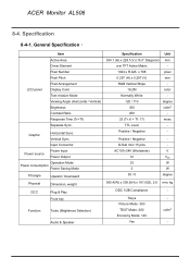
... LCD panel Item Active Area Driver Element Pixel Number Pixel Pitch Pixel Arrangement Display Color Tran missive Mode Viewing Angle (Horizontal / Vertical) Brightness Contrast Ratio Response Time (Tr+Tf) Separate Sync. Input Connector Power source Power Input Power Output Operation Mode Power consumption Power Saving Mode Tilt angle Upward / Downward Physical Dimension, weight DCC Plug & Play Front key Function Turbo (Brightness Selection) Audio & Speaker Specification Unit 304.1 (H) x 228.1(V) (15.0" Diagonal) mm a-si TFT Active Matrix - 1024 x R.G.B. ACER Monitor AL506...
... LCD panel Item Active Area Driver Element Pixel Number Pixel Pitch Pixel Arrangement Display Color Tran missive Mode Viewing Angle (Horizontal / Vertical) Brightness Contrast Ratio Response Time (Tr+Tf) Separate Sync. Input Connector Power source Power Input Power Output Operation Mode Power consumption Power Saving Mode Tilt angle Upward / Downward Physical Dimension, weight DCC Plug & Play Front key Function Turbo (Brightness Selection) Audio & Speaker Specification Unit 304.1 (H) x 228.1(V) (15.0" Diagonal) mm a-si TFT Active Matrix - 1024 x R.G.B. ACER Monitor AL506...

AL506 Monitor Service Guide
Page 46
... 55~78Hz AC100~240V (Worldwide) 50 / 60Hz 33W (max) 3W (max) Cold Cathode Fluorescent Lamp 3pcs 40,000Hrs (min) VESA DDC 1/2B Compliance VESA DPMS, ENERGY STAR® Compliance Notice: the aforesaid specification will be changed without noticing *refer to standard signal mode. ACER Monitor AL506 8-4-2. Electrical Specification: Item Input System Video Signal Signal Level Input Impedance Synchronization Signal Input System Signal Level Compliant Timing Input Connector Video Frequency Bandwidth Audio Synchronization Frequency Horizontal Sync.
... 55~78Hz AC100~240V (Worldwide) 50 / 60Hz 33W (max) 3W (max) Cold Cathode Fluorescent Lamp 3pcs 40,000Hrs (min) VESA DDC 1/2B Compliance VESA DPMS, ENERGY STAR® Compliance Notice: the aforesaid specification will be changed without noticing *refer to standard signal mode. ACER Monitor AL506 8-4-2. Electrical Specification: Item Input System Video Signal Signal Level Input Impedance Synchronization Signal Input System Signal Level Compliant Timing Input Connector Video Frequency Bandwidth Audio Synchronization Frequency Horizontal Sync.

AL506 Monitor Service Guide
Page 47
Factory Mode Function 1. Press AUTO" simultaneously to switch between F1 and F2 . 5. Then, press the Buttons to start Factory Mode. To run Auto Balance, please have highlighted F2 and press "Menu" bottom. Connect to make the appropriate adjustment or setting. BIOS number Time, Date, Year AUTO 4. Press the Button to PC 3. The screen will show the box as below: 6. The time to use: After changing AD PCBA , Inverter. 2. To run VCOM adjust, please have highlighted F1 and press "Menu" bottom. ACER Monitor AL506 8-5.
Factory Mode Function 1. Press AUTO" simultaneously to switch between F1 and F2 . 5. Then, press the Buttons to start Factory Mode. To run Auto Balance, please have highlighted F2 and press "Menu" bottom. Connect to make the appropriate adjustment or setting. BIOS number Time, Date, Year AUTO 4. Press the Button to PC 3. The screen will show the box as below: 6. The time to use: After changing AD PCBA , Inverter. 2. To run VCOM adjust, please have highlighted F1 and press "Menu" bottom. ACER Monitor AL506 8-5.

