
AL1916e Service Guide
Page 8
Table of contents Chapter 1 MONITOR FEATURE 9 Chapter 2 OPERATING INSTRUTION 16 Chapter 3 MACHINE ASSEMBLY 21 Chapter 4 TROUBLE SHOOTING 32 Chapter 5 CONNECTOR INFORMATION 34 Chapter 6 FRU LIST 35 Chapter 7 SCHEMATIC DIAGRAM 36 Chapter 8 POWER BOARD INFORMATION 40 - 8 -
Table of contents Chapter 1 MONITOR FEATURE 9 Chapter 2 OPERATING INSTRUTION 16 Chapter 3 MACHINE ASSEMBLY 21 Chapter 4 TROUBLE SHOOTING 32 Chapter 5 CONNECTOR INFORMATION 34 Chapter 6 FRU LIST 35 Chapter 7 SCHEMATIC DIAGRAM 36 Chapter 8 POWER BOARD INFORMATION 40 - 8 -

AL1916e Service Guide
Page 32
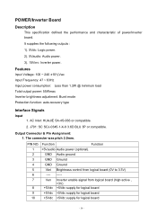
OK Check Power Button From Scalar/B(CN6) to Button/B(CN1) NO Change Scalar Module Board NO Check Cable Yes Open ? R98 = 1.8V ? Chapter 4 TROUBLE SHOOTING This chapter provides trouble shooting information forAL1916 1. R99 = 3.3V ? Change Cable NO Change Switch or Button Board - 32 - No Power No Power Check Power Board Output CN4 Pin 5,Pin6 =5V NO Change Adaptor Power Board OK Check Scalar Module Output R96 =5V?
OK Check Power Button From Scalar/B(CN6) to Button/B(CN1) NO Change Scalar Module Board NO Check Cable Yes Open ? R98 = 1.8V ? Chapter 4 TROUBLE SHOOTING This chapter provides trouble shooting information forAL1916 1. R99 = 3.3V ? Change Cable NO Change Switch or Button Board - 32 - No Power No Power Check Power Board Output CN4 Pin 5,Pin6 =5V NO Change Adaptor Power Board OK Check Scalar Module Output R96 =5V?

AL1916e Service Guide
Page 40
Power Board Information Panel P/N AAM190EN129(AU) AA0190EA108(CPT) Description Chapter 8 Current Type Value P/B P/N AS05B312D00 AS05B520207 Description ADP/INV,FSP043-2PI01 90~264V GP ADP/INV,SLS0532D0248,90~264V,REV1A GP When the lamp current value is 7.0mA, the jumper should be done as the picture left shows - - 40 -
Power Board Information Panel P/N AAM190EN129(AU) AA0190EA108(CPT) Description Chapter 8 Current Type Value P/B P/N AS05B312D00 AS05B520207 Description ADP/INV,FSP043-2PI01 90~264V GP ADP/INV,SLS0532D0248,90~264V,REV1A GP When the lamp current value is 7.0mA, the jumper should be done as the picture left shows - - 40 -
AL1916p Service Guide
Page 7
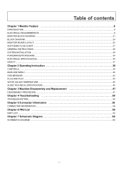
Table of contents Chapter 1 Monitor Feature 8 INTRODUCTION...8 ELECTRICAL REQUIREMEENTS...9 MONITOR BLOCK DIAGRAM ...21 BLOCK DIAGRAM ...24 MONITOR BOARD LAYOUT ...25 SOFTWARE FLOW CHART ...27 GENERAL INSTRUCTIONS ...28 SYSTEM INSTALLATION ...29 POWER/INVERTOR BOARD ...34 ELECTRICAL SPECIFICATION...35 SAFETY ...37 Chapter 2 Operating Instruction 39 CONTROLS ...39 MAIN OSD MENU ...40 OSD MESSAGE...42 PLUG...
Table of contents Chapter 1 Monitor Feature 8 INTRODUCTION...8 ELECTRICAL REQUIREMEENTS...9 MONITOR BLOCK DIAGRAM ...21 BLOCK DIAGRAM ...24 MONITOR BOARD LAYOUT ...25 SOFTWARE FLOW CHART ...27 GENERAL INSTRUCTIONS ...28 SYSTEM INSTALLATION ...29 POWER/INVERTOR BOARD ...34 ELECTRICAL SPECIFICATION...35 SAFETY ...37 Chapter 2 Operating Instruction 39 CONTROLS ...39 MAIN OSD MENU ...40 OSD MESSAGE...42 PLUG...
AL1916p Service Guide
Page 21
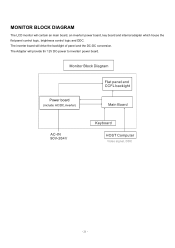
MONITOR BLOCK DIAGRAM The LCD monitor will drive the backlight of panel and the DC-DC conversion. The inverter board will contain an main board, an inverter/ power board, key board and internal adapter which house the flat panel control logic, brightness control logic and DDC. The Adapter will provide thr 12V DC-power to inverter/ power board. Power board (include: AC/DC,inverter) - 21 -
MONITOR BLOCK DIAGRAM The LCD monitor will drive the backlight of panel and the DC-DC conversion. The inverter board will contain an main board, an inverter/ power board, key board and internal adapter which house the flat panel control logic, brightness control logic and DDC. The Adapter will provide thr 12V DC-power to inverter/ power board. Power board (include: AC/DC,inverter) - 21 -
AL1916p Service Guide
Page 34
... Audio ground 3 GND Ground 4 GND Ground 5 Vbri Brightness control from logical board (0V to 3.3V) 6 ---- ----- 7 Ven Inverter enable signal from logical board (high active , >3V) 8 +5Vdc +5Vdc supply for logical board 9 +5Vdc +5Vdc supply for logical board 10 +5Vdc +5Vdc supply for logical board - 34 - AC Inlet: HUAJIE SA-4S-066 or compatible. 2. POWER/Inverter...
... Audio ground 3 GND Ground 4 GND Ground 5 Vbri Brightness control from logical board (0V to 3.3V) 6 ---- ----- 7 Ven Inverter enable signal from logical board (high active , >3V) 8 +5Vdc +5Vdc supply for logical board 9 +5Vdc +5Vdc supply for logical board 10 +5Vdc +5Vdc supply for logical board - 34 - AC Inlet: HUAJIE SA-4S-066 or compatible. 2. POWER/Inverter...
AL1916p Service Guide
Page 48
.... 6. Disassemble the two speaker lines from Chassis. 5. Then take the power board from VL board. 3. Disassemble two VL-VK lines from the chassia. Remove the one screw to release VK board from power board. 2. Disassemble audio line from VL board. 5. Disassemble FPC line from power board. 2. Disassemble two voltage lines from bezel. 2. Remove the one screw...
.... 6. Disassemble the two speaker lines from Chassis. 5. Then take the power board from VL board. 3. Disassemble two VL-VK lines from the chassia. Remove the one screw to release VK board from power board. 2. Disassemble audio line from VL board. 5. Disassemble FPC line from power board. 2. Disassemble two voltage lines from bezel. 2. Remove the one screw...

AL1916p Service Guide
Page 49
Disassemble the speakers 1. Remove the two screws to release line and VK board from bezel. 2. Remove the two screws to release line and chassis from bezel. 49 Remove the four screws from bezel. 3.
Disassemble the speakers 1. Remove the two screws to release line and VK board from bezel. 2. Remove the two screws to release line and chassis from bezel. 49 Remove the four screws from bezel. 3.
AL1916p Service Guide
Page 58
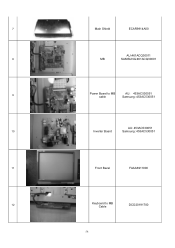
7 Main Shield ECAR9914A00 AU:461ACQ30011 8 MB SAMSUNG:461ACQ30001 9 Power Board to MB cable AU: 453AC530051 Samsung: 453AC530051 AU: 453AC530051 10 Inverter Board Samsung: 453AC530051 11 Front Bezel FAAA6911000 12 Keyboard to MB Cable DCO20191700 58
7 Main Shield ECAR9914A00 AU:461ACQ30011 8 MB SAMSUNG:461ACQ30001 9 Power Board to MB cable AU: 453AC530051 Samsung: 453AC530051 AU: 453AC530051 10 Inverter Board Samsung: 453AC530051 11 Front Bezel FAAA6911000 12 Keyboard to MB Cable DCO20191700 58

AL1916p Service Guide
Page 59
13 Frame ECAR9915A00 14 LCD (R) AC6VA1901R0 AC6VT1901R5 15 Panel to MB cable NBX30001271 NBX30001600 16 Function Board 454AC830001 59
13 Frame ECAR9915A00 14 LCD (R) AC6VA1901R0 AC6VT1901R5 15 Panel to MB cable NBX30001271 NBX30001600 16 Function Board 454AC830001 59

AL1916p Service Guide
Page 63
... 21 E EPROM C49 0 .1u F U6 SO-8 1 2 3 4 NC VCC NC WC NC SCL GND SDA 8 7 6 5 ST_M24C16-WMN6T VDD 1 1 R62 2.2K R63 2.2K 2 2 WP SC L SD A 4 K EY BOARD-INTERFACE VDD K EY PULL HIGN DESIGN B 1 1 1 1 1 1 CN 3 1 2 PLED- C OM PAL E LEC TR ONIC S, INC." DEC K EY-AUTO 2 R49 R50 R51 R52 R53 R54 10K 10K...
... 21 E EPROM C49 0 .1u F U6 SO-8 1 2 3 4 NC VCC NC WC NC SCL GND SDA 8 7 6 5 ST_M24C16-WMN6T VDD 1 1 R62 2.2K R63 2.2K 2 2 WP SC L SD A 4 K EY BOARD-INTERFACE VDD K EY PULL HIGN DESIGN B 1 1 1 1 1 1 CN 3 1 2 PLED- C OM PAL E LEC TR ONIC S, INC." DEC K EY-AUTO 2 R49 R50 R51 R52 R53 R54 10K 10K...
AL1916v Service Guide
Page 6
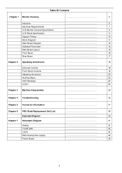
... Contents Chapter 1 Monitor Features 6 Induction Electrical Requirements LCD Monitor General Specification LCD Panel Specification Support Timing Block Diagram Main Board Diagram Software Flow chart Main Board Layout Front Bezel Rear Bezel Chapter 2 Operating Instructions External Controls Front Panel Controls Adjusting the picture Hot-Key Menu OSD ... Information 37 Chapter 6 FRU (Field Replacement Unit) List 38 Exploded Diagram 39 Chapter 7 Schematic Diagram 41 Analog TSUM16AK LVDS Main board power supply Power Board 41 42 43 44 45 5
... Contents Chapter 1 Monitor Features 6 Induction Electrical Requirements LCD Monitor General Specification LCD Panel Specification Support Timing Block Diagram Main Board Diagram Software Flow chart Main Board Layout Front Bezel Rear Bezel Chapter 2 Operating Instructions External Controls Front Panel Controls Adjusting the picture Hot-Key Menu OSD ... Information 37 Chapter 6 FRU (Field Replacement Unit) List 38 Exploded Diagram 39 Chapter 7 Schematic Diagram 41 Analog TSUM16AK LVDS Main board power supply Power Board 41 42 43 44 45 5
AL1916v Service Guide
Page 12
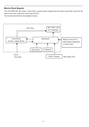
The Inverter board will contain a main board, a power board, keypad board and audio board which house the flat panel control logic, brightness control logic and DDC. Monitor Block Diagram The LCD MONITOR will drive the backlight of panel. CCFL Drive. Flat Panel and CCFL backlight Power Board (Inverter, adapter Board) AC-IN 100V-240V Main Board Audio board Keyboard RS232 Connector For white balance adjustment in factory mode HOST Computer Video signal, DDC 11
The Inverter board will contain a main board, a power board, keypad board and audio board which house the flat panel control logic, brightness control logic and DDC. Monitor Block Diagram The LCD MONITOR will drive the backlight of panel. CCFL Drive. Flat Panel and CCFL backlight Power Board (Inverter, adapter Board) AC-IN 100V-240V Main Board Audio board Keyboard RS232 Connector For white balance adjustment in factory mode HOST Computer Video signal, DDC 11

AL1916v Service Guide
Page 27
Remove nine screws to release back cover and front bezel. (Fig 3) 2. Disassemble the front cover and rear bezel 1. Remove connector wire with keyboard and main board. (Fig 4) Fig 3 Fig 4 26
Remove nine screws to release back cover and front bezel. (Fig 3) 2. Disassemble the front cover and rear bezel 1. Remove connector wire with keyboard and main board. (Fig 4) Fig 3 Fig 4 26

AL1916v Service Guide
Page 29
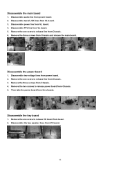
Disassemble the main board 1. Remove three screws to release main board. (Fig 6) 2. Remove connector wire with main board and panel. (Fig 7) Fig 6 Fig 7 28
Disassemble the main board 1. Remove three screws to release main board. (Fig 6) 2. Remove connector wire with main board and panel. (Fig 7) Fig 6 Fig 7 28

AL1916v Service Guide
Page 30
Remove connector wire with main board and KEPC board. (Fig 9) Fig 8 Fig 9 29 3. Remove connector wire with main board and power board. (Fig 8) 4.
Remove connector wire with main board and KEPC board. (Fig 9) Fig 8 Fig 9 29 3. Remove connector wire with main board and power board. (Fig 8) 4.

AL1916v Service Guide
Page 31
Remove four screws to release power board. (Fig 10) 2. Remove connector wire with power board and panel. (Fig 11) Fig 10 Fig 11 30 Disassemble the power board 1.
Remove four screws to release power board. (Fig 10) 2. Remove connector wire with power board and panel. (Fig 11) Fig 10 Fig 11 30 Disassemble the power board 1.
AL1916v Service Guide
Page 35
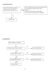
Keypad Board OSD is unstable or not working NG Is Keypad board connecting normally? OK NG Is Keypad board normally? OK Check main board 34 Connect Keypad Board Replace Button Switch Replace Keypad Board OK NG Is Button Switch normally? Panel Power Circuit Check CN101 PIN 23-24 should have response from 0V to 5V When we switch the power switch from on to off OK Replace panel Check the PPWR panel power relative circuit,Q706, Q704 In normal operation, when LED =green, R725 NG Should =5 V, If PPWR no-response when the power switch Turn on and turn off, replace the U401-TSUM16AK 4. 3.
Keypad Board OSD is unstable or not working NG Is Keypad board connecting normally? OK NG Is Keypad board normally? OK Check main board 34 Connect Keypad Board Replace Button Switch Replace Keypad Board OK NG Is Button Switch normally? Panel Power Circuit Check CN101 PIN 23-24 should have response from 0V to 5V When we switch the power switch from on to off OK Replace panel Check the PPWR panel power relative circuit,Q706, Q704 In normal operation, when LED =green, R725 NG Should =5 V, If PPWR no-response when the power switch Turn on and turn off, replace the U401-TSUM16AK 4. 3.

AL1916v Service Guide
Page 37
No Backlight Check C201 (+) =12V NG OK Change F902 Check Q203/D201 Check ON/OFF signal NG OK Check U201 pin9=12V ? NG CheckQ205/Q207/Q203/Q201or OK /Q206/Q208/Q204/D202 Check the resonant wave of pin2 & pin5 for PT201/ PT202 OK NG Check Q206/Q207/C211 Check the output of square wave at short time. Check Interface board NG OK Check the pin1 of U201 have saw tooth wave Change Q201 or Q202 NG Change U201 OK Check D201 (-) has the output of PT201/PT202 NG OK Check connecter & lamp Change PT201/PT202 36
No Backlight Check C201 (+) =12V NG OK Change F902 Check Q203/D201 Check ON/OFF signal NG OK Check U201 pin9=12V ? NG CheckQ205/Q207/Q203/Q201or OK /Q206/Q208/Q204/D202 Check the resonant wave of pin2 & pin5 for PT201/ PT202 OK NG Check Q206/Q207/C211 Check the output of square wave at short time. Check Interface board NG OK Check the pin1 of U201 have saw tooth wave Change Q201 or Q202 NG Change U201 OK Check D201 (-) has the output of PT201/PT202 NG OK Check connecter & lamp Change PT201/PT202 36
AL1916v Service Guide
Page 38
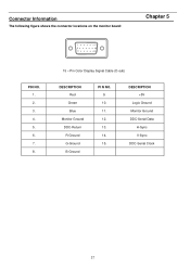
DESCRIPTION +5V Logic Ground Monitor Ground DDC-Serial Data H-Sync V-Sync DDC-Serial Clock 37 Pin Color Display Signal Cable (D-sub) DESCRIPTION Red Green Blue Monitor Ground DDC-Return R-Ground G-Ground B-Ground PI N NO. 9. 10. 11. 12. 13. 14. 15. Connector Information The following figure shows the connector locations on the monitor board: Chapter 5 1 5 6 10 11 15 PIN NO. 1. 2. 3. 4. 5. 6. 7. 8. 15 -
DESCRIPTION +5V Logic Ground Monitor Ground DDC-Serial Data H-Sync V-Sync DDC-Serial Clock 37 Pin Color Display Signal Cable (D-sub) DESCRIPTION Red Green Blue Monitor Ground DDC-Return R-Ground G-Ground B-Ground PI N NO. 9. 10. 11. 12. 13. 14. 15. Connector Information The following figure shows the connector locations on the monitor board: Chapter 5 1 5 6 10 11 15 PIN NO. 1. 2. 3. 4. 5. 6. 7. 8. 15 -

