

al1511ug.pdf
Page 1
. TABLE OF CONTENTS FOR YOUR SAFETY 1 SAFETY PRECAUTIONS 2 SPECIAL NOTES ON LCD MONITORS 3 BEFORE YOU OPERATE THE MONITOR 3 FEATURES 3 PACKING LIST 3 INSTALLATION INSTRUCTIONS 4 CONTROLS AND CONNECTORS 5 ADJUSTING THE VIEWING ANGLE 6 OPERATING INSTRUCTIONS 7 GENERAL INSTRUCTIONS 7 HOW TO ADJUST A SETTING 9 ADJUSTING THE PICTURE 9-10 PLUG AND PLAY 11 TECHNICAL SUPPORT(FAQ 12-13 ERROR MESSAGE & POSSIBLE SOLUTION ------- 14 APPENDIX 15 SPECIFICATIONS 15-16 FACTORY PRESET TIMING TABLE 17 CONNECTOR PIN ASSIGNMENT 17
. TABLE OF CONTENTS FOR YOUR SAFETY 1 SAFETY PRECAUTIONS 2 SPECIAL NOTES ON LCD MONITORS 3 BEFORE YOU OPERATE THE MONITOR 3 FEATURES 3 PACKING LIST 3 INSTALLATION INSTRUCTIONS 4 CONTROLS AND CONNECTORS 5 ADJUSTING THE VIEWING ANGLE 6 OPERATING INSTRUCTIONS 7 GENERAL INSTRUCTIONS 7 HOW TO ADJUST A SETTING 9 ADJUSTING THE PICTURE 9-10 PLUG AND PLAY 11 TECHNICAL SUPPORT(FAQ 12-13 ERROR MESSAGE & POSSIBLE SOLUTION ------- 14 APPENDIX 15 SPECIFICATIONS 15-16 FACTORY PRESET TIMING TABLE 17 CONNECTOR PIN ASSIGNMENT 17

al1511ug.pdf
Page 2
Before operating the monitor, please read this equipment does cause harmful interference to operate the equipment. 2. Connect the equipment into... found to provide reasonable protection against harmful interference in accordance with the emission limits. 3. These limits are present inside the monitor. Consult the dealer or an experienced radio/TV technician for any , must be retained for compliance could void the user's... separation between the equipment and receiver. 3. WARNING: To prevent fire or shock hazard, do not expose the monitor to qualified personnel only. 1
Before operating the monitor, please read this equipment does cause harmful interference to operate the equipment. 2. Connect the equipment into... found to provide reasonable protection against harmful interference in accordance with the emission limits. 3. These limits are present inside the monitor. Consult the dealer or an experienced radio/TV technician for any , must be retained for compliance could void the user's... separation between the equipment and receiver. 3. WARNING: To prevent fire or shock hazard, do not expose the monitor to qualified personnel only. 1
al1511ug.pdf
Page 3
...by the manufacturer or sold with a third (grounding) pin. z Slots and openings in a wet basement. Do not place the monitor on an unstable cart, stand, or table. z The monitor should be used for ventilation. If your dealer or local power company. Do not defeat the safety purpose of the...opening or removing covers can result in a bookcase or cabinet unless proper ventilation is equipped with a three-pronged grounded plug, a plug with the monitor. z The wall socket shall be sure these openings are not blocked or covered. Overloading can expose you are not sure of the type of power...
...by the manufacturer or sold with a third (grounding) pin. z Slots and openings in a wet basement. Do not place the monitor on an unstable cart, stand, or table. z The monitor should be used for ventilation. If your dealer or local power company. Do not defeat the safety purpose of the...opening or removing covers can result in a bookcase or cabinet unless proper ventilation is equipped with a three-pronged grounded plug, a plug with the monitor. z The wall socket shall be sure these openings are not blocked or covered. Overloading can expose you are not sure of the type of power...
al1511ug.pdf
Page 4
... sure the flicker disappears. • You may find slightly uneven brightness on the screen depending on the desktop pattern you use . BEFORE YOU OPERATE THE MONITOR FEATURES • 38.1cm(15") TFT Color LCD Monitor • Crisp, Clear Display for hours. Power Cord 4. 15-pin D-Sub Cable 5. SPECIAL NOTES ON LCD... MONITORS The following items: 1. LCD Monitor 2. Audio Cable(Option-only for hours. It may include blemishes of 0.01% or less such as a missing pixel or a pixel lit all of the time. &#...
... sure the flicker disappears. • You may find slightly uneven brightness on the screen depending on the desktop pattern you use . BEFORE YOU OPERATE THE MONITOR FEATURES • 38.1cm(15") TFT Color LCD Monitor • Crisp, Clear Display for hours. Power Cord 4. 15-pin D-Sub Cable 5. SPECIAL NOTES ON LCD... MONITORS The following items: 1. LCD Monitor 2. Audio Cable(Option-only for hours. It may include blemishes of 0.01% or less such as a missing pixel or a pixel lit all of the time. &#...

al1511ug.pdf
Page 5
...75mm2) shall be used. Connect the AC-power cord into your area. 2. Alternative a flexible cord be used with your LCD monitor. This LCD monitor has an External universal power supply that the power cord is required.) 3. A certified power supply cord not lighter than ordinary polyvinyl ... (designation H05RR-F 3G 0.75mm2) shall be of power cord supplied with this equipment. Make sure that allows operation in your LCD monitor's DC-power-input. The AC-power cord may be connected to be considered. INSTALLATION INSTRUCTIONS SWIVEL BASE IVEL BASE Install Remove POWERCORD ...
...75mm2) shall be used. Connect the AC-power cord into your area. 2. Alternative a flexible cord be used with your LCD monitor. This LCD monitor has an External universal power supply that the power cord is required.) 3. A certified power supply cord not lighter than ordinary polyvinyl ... (designation H05RR-F 3G 0.75mm2) shall be of power cord supplied with this equipment. Make sure that allows operation in your LCD monitor's DC-power-input. The AC-power cord may be connected to be considered. INSTALLATION INSTRUCTIONS SWIVEL BASE IVEL BASE Install Remove POWERCORD ...

al1511ug.pdf
Page 6
Plug the other end to the back of the monitor and connect the other end of your monitor into the PC port. Power Cable 2. 3. Connect the audio cable: Plug the power cable of the power cord into a nearby outlet. ATTENTION: If the AC ... not grounded, install the proper grounding adapter (not supplied). 3 Figure 1 Connecting Cables 1. Audio cable (Option-only for Audio model)Connect the audio cable between the monitor's audio input and the PC's audio output (green port). CONTROLS AND CONNECTORS CABLE CONNECTIONS Connect the signal cable: Connect one end of the 15-pin...
Plug the other end to the back of the monitor and connect the other end of your monitor into the PC port. Power Cable 2. 3. Connect the audio cable: Plug the power cable of the power cord into a nearby outlet. ATTENTION: If the AC ... not grounded, install the proper grounding adapter (not supplied). 3 Figure 1 Connecting Cables 1. Audio cable (Option-only for Audio model)Connect the audio cable between the monitor's audio input and the PC's audio output (green port). CONTROLS AND CONNECTORS CABLE CONNECTIONS Connect the signal cable: Connect one end of the 15-pin...
al1511ug.pdf
Page 7
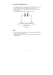
ADJUSTING THE VIEWING ANGLE • For optimal viewing it is required not to catch your own preference. • Hold the stand so you do not topple the monitor when you change the angle. 6 It may cause damage or break the LCD screen. • Careful attention is recommended to look at the full face of the monitor, then adjust the monitor's angle to 20°. Figure 2 NOTES • Do not touch the LCD screen when you change the monitor's angle. • You are able to adjust the monitor's angle from -5° to your fingers or hands when you change the angle.
ADJUSTING THE VIEWING ANGLE • For optimal viewing it is required not to catch your own preference. • Hold the stand so you do not topple the monitor when you change the angle. 6 It may cause damage or break the LCD screen. • Careful attention is recommended to look at the full face of the monitor, then adjust the monitor's angle to 20°. Figure 2 NOTES • Do not touch the LCD screen when you change the monitor's angle. • You are able to adjust the monitor's angle from -5° to your fingers or hands when you change the angle.
al1511ug.pdf
Page 8
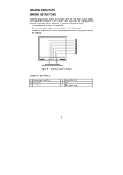
...Figure 3). Figure 3 External Control Button EXTERNAL CONTROLS 1. MENU/ENTER 5. OPERATING INSTRUCTIONS GENERAL INSTRUCTIONS Press the power button to turn the monitor on the monitor position. LED 6. /Power Key 7 By changing these settings, the picture can be adjusted to your personal preferences. • ...The power cord should be connected. • Connect the video cable from the monitor to the video card. • Press the power button ...
...Figure 3). Figure 3 External Control Button EXTERNAL CONTROLS 1. MENU/ENTER 5. OPERATING INSTRUCTIONS GENERAL INSTRUCTIONS Press the power button to turn the monitor on the monitor position. LED 6. /Power Key 7 By changing these settings, the picture can be adjusted to your personal preferences. • ...The power cord should be connected. • Connect the video cable from the monitor to the video card. • Press the power button ...

al1511ug.pdf
Page 9
... HPos, VPos, Clock and Focus. When OSD menu is activated. • Auto Adjust button / Exit: 1. As a safety precaution, always unplug the monitor before cleaning it with a mild detergent solution. FRONT PANEL CONTROL • /Power Button: Press this button will act as thinner, benzene, or abrasive cleaners...de-activate adjustment function when OSD is ON or Exit OSD menu when in handy if you ever have to turn the monitor ON or OFF, And display the monitor's state. • Power Indicator: Green - Stubborn stains may be removed with a cloth lightly dampened with a soft cloth...
... HPos, VPos, Clock and Focus. When OSD menu is activated. • Auto Adjust button / Exit: 1. As a safety precaution, always unplug the monitor before cleaning it with a mild detergent solution. FRONT PANEL CONTROL • /Power Button: Press this button will act as thinner, benzene, or abrasive cleaners...de-activate adjustment function when OSD is ON or Exit OSD menu when in handy if you ever have to turn the monitor ON or OFF, And display the monitor's state. • Power Indicator: Green - Stubborn stains may be removed with a cloth lightly dampened with a soft cloth...

al1511ug.pdf
Page 12
... EDID information over the DDC2B channel. This feature is designed to inform the host system of its display capabilities. This reduces the monitor's internal power supply consumption. Supplied with units intended for the power cord shall be 125 volts AC. Please note that power supply...0625, 0821 approval power cord in two levels, DDC1 and DDC2B. The communication channel is defined in European counties. 11 This monitor meets the Green monitor standards as set consisting of DDC used, communicate additional information about its identity and, depending on the keyboard, or clicking the ...
... EDID information over the DDC2B channel. This feature is designed to inform the host system of its display capabilities. This reduces the monitor's internal power supply consumption. Supplied with units intended for the power cord shall be 125 volts AC. Please note that power supply...0625, 0821 approval power cord in two levels, DDC1 and DDC2B. The communication channel is defined in European counties. 11 This monitor meets the Green monitor standards as set consisting of DDC used, communicate additional information about its identity and, depending on the keyboard, or clicking the ...

al1511ug.pdf
Page 13
... that may cause electrical interference. *Computer Power Switch should be snugly seated in the picture The power LED is properly connected to the computer. *Inspect monitor's video cable and make sure that none of the pins are bent. 12 The LED should be in the ON position. *Computer Video Card should... either turn ON or OFF after hitting the CAPS LOCK key. *Inspect the monitor's video cable and make sure none of the pins are bent. *Make sure computer is operational by hitting the CAPS LOCK key on No Plug...
... that may cause electrical interference. *Computer Power Switch should be snugly seated in the picture The power LED is properly connected to the computer. *Inspect monitor's video cable and make sure that none of the pins are bent. 12 The LED should be in the ON position. *Computer Video Card should... either turn ON or OFF after hitting the CAPS LOCK key. *Inspect the monitor's video cable and make sure none of the pins are bent. *Make sure computer is operational by hitting the CAPS LOCK key on No Plug...
AL1511 Monitor Service Guide
Page 8
Table of Contents Chapter 1 Monitor Features 8 Monitor Features 8 Factory Preset Timing Table 10 Block Diagram 11 Mainboard Diagram 12 Software Flowchart 13 Mainboard Layout 15 Invertor Board Layout 17 Front Bezel View ...
Table of Contents Chapter 1 Monitor Features 8 Monitor Features 8 Factory Preset Timing Table 10 Block Diagram 11 Mainboard Diagram 12 Software Flowchart 13 Mainboard Layout 15 Invertor Board Layout 17 Front Bezel View ...

AL1511 Monitor Service Guide
Page 15
... chip will be initialized 6. Read EEPROM content to 8. 7. Check if input timing has been changed, if yes then go to 10, else go to recover monitor settings, including brightness, contrast, color temperature and OSD position ....
... chip will be initialized 6. Read EEPROM content to 8. 7. Check if input timing has been changed, if yes then go to 10, else go to recover monitor settings, including brightness, contrast, color temperature and OSD position ....
AL1511 Monitor Service Guide
Page 29
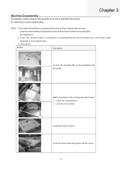
NOTE: 1.The screws for maintenance and troubleshooting. Machine Disassembly This chapter contains step-by-step procedures on how to avoid mismatch when putting back the components. 2. 3. During the disassembly process, group the screws with the corresponding components to assemble the monitor for the different components vary in size.
NOTE: 1.The screws for maintenance and troubleshooting. Machine Disassembly This chapter contains step-by-step procedures on how to avoid mismatch when putting back the components. 2. 3. During the disassembly process, group the screws with the corresponding components to assemble the monitor for the different components vary in size.
AL1511 Monitor Service Guide
Page 35
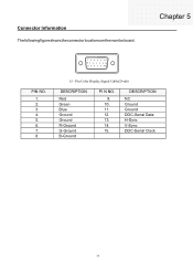
The following figure shows the connector locations on the monitor board:
The following figure shows the connector locations on the monitor board:
AL1511 Monitor Service Guide
Page 36
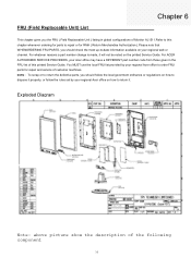
NOTE: Exploded Diagram Monitor AL1511 Note: above picture show the description of the following component
NOTE: Exploded Diagram Monitor AL1511 Note: above picture show the description of the following component


