
User Manual
Page 8
...; K-Series unlocked CPU • Supports ASRock BCLK Full-range Overclocking quality Conductive Polymer Capacitors) A-Style • Home Cloud • Conformal Coating • Purity SoundTM • 802.11ac WiFi (for Z87 OC Formula/ac only) • HDMI-In OC Formula Kit OC Formula Power Kit • 12 Power Phase ...70% core loss compare to iron powder choke) OC Formula Connector Kit • Hi-Density Power Connector (8 pin) • 15μGold Finger (CPU sockets, memory sockets and PCIE x16 slots) • Distortion-Free Slot OC Formula Cooling Kit • Twin-Power Cooling (Combine ...
...; K-Series unlocked CPU • Supports ASRock BCLK Full-range Overclocking quality Conductive Polymer Capacitors) A-Style • Home Cloud • Conformal Coating • Purity SoundTM • 802.11ac WiFi (for Z87 OC Formula/ac only) • HDMI-In OC Formula Kit OC Formula Power Kit • 12 Power Phase ...70% core loss compare to iron powder choke) OC Formula Connector Kit • Hi-Density Power Connector (8 pin) • 15μGold Finger (CPU sockets, memory sockets and PCIE x16 slots) • Distortion-Free Slot OC Formula Cooling Kit • Twin-Power Cooling (Combine ...
User Manual
Page 11
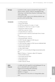
...8226; CPU, DRAM, PCH 1.05V, PCH 1.5V Voltage Multi-adjust- ment 5 English Z87 OC Formula/ac / Z87 OC Formula Storage • 6 x SATA3 6.0 Gb/s connectors by Intel® Z87, support RAID (RAID 0, RAID 1, RAID 5, RAID 10, Intel Rapid Storage Technology 12...COM port header • 1 x Power LED header • 2 x CPU Fan connectors (1 x 4-pin, 1 x 3-pin) • 4 x Chassis Fan connectors (1 x 4-pin, 3 x 3-pin) • 1 x Power Fan connector (3-pin) • 1 x MOS Fan connector (3-pin) • 1 x 24 pin ATX power connector • 2 x 8 pin 12V power connectors (Hi-Density Power Connec-
...8226; CPU, DRAM, PCH 1.05V, PCH 1.5V Voltage Multi-adjust- ment 5 English Z87 OC Formula/ac / Z87 OC Formula Storage • 6 x SATA3 6.0 Gb/s connectors by Intel® Z87, support RAID (RAID 0, RAID 1, RAID 5, RAID 10, Intel Rapid Storage Technology 12...COM port header • 1 x Power LED header • 2 x CPU Fan connectors (1 x 4-pin, 1 x 3-pin) • 4 x Chassis Fan connectors (1 x 4-pin, 3 x 3-pin) • 1 x Power Fan connector (3-pin) • 1 x MOS Fan connector (3-pin) • 1 x 24 pin ATX power connector • 2 x 8 pin 12V power connectors (Hi-Density Power Connec-
User Manual
Page 16
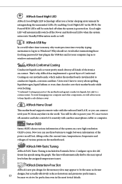
... buttons to power your PC on . ASRock FAN-Tastic Tuning ASRock FAN-Tastic Tuning is powered on or turn it remotely with another smartphone, tablet or computer. English ASRock Distortion-Free Slot ASRock's new pin design for the memory slots may protect ...designs, but only to five different fan speeds using the graph. Configure up to a certain extent. ASRock Good Night LED ASRock Good Night LED technology offers you can connect with your PC from anywhere in the world. Users won't...Power/HDD LEDs will automatically switch off when the system is included in Formula Drive.
... buttons to power your PC on . ASRock FAN-Tastic Tuning ASRock FAN-Tastic Tuning is powered on or turn it remotely with another smartphone, tablet or computer. English ASRock Distortion-Free Slot ASRock's new pin design for the memory slots may protect ...designs, but only to five different fan speeds using the graph. Configure up to a certain extent. ASRock Good Night LED ASRock Good Night LED technology offers you can connect with your PC from anywhere in the world. Users won't...Power/HDD LEDs will automatically switch off when the system is included in Formula Drive.
User Manual
Page 17
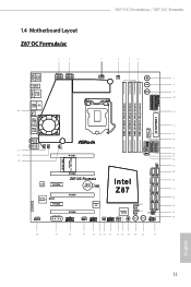
Z87 OC Formula/ac / Z87 OC Formula 1.4 Motherboard Layout Z87 OC Formula/ac 1 2 3 4 5 6 HDMI2 USB 3.0 T: USB0 B: USB1 HDMI1 USB 3.0 T: USB2 Top: RJ-45 B: USB3 44 USB 2.0 T: USB0 B: USB1 PS2 Keyboard /Mouse ATX12V1 ATX12V3 CPU_FAN1 CPU_FAN2 + 7 - 8 MENU 9 10 11 DDR3_A1 (64 bit, 240-pin module) DDR3_A2 (64 bit, 240-pin module) DDR3_B1 (64 bit, 240-pin module) DDR3_B2 (64 bit, 240-pin...17 18 19 WiFi-802.11n Module MINI_PCIE1 20 PCIE2 Z87 OC Formula Intel 21 LAN PCIE3 CMOS CLRCMOS1 Battery 1 Z87 22 Purity RoHS SoundTM PCIE5 PCIE4 HD_AUDIO1 1 SLI/XFIRE_PWR1...
Z87 OC Formula/ac / Z87 OC Formula 1.4 Motherboard Layout Z87 OC Formula/ac 1 2 3 4 5 6 HDMI2 USB 3.0 T: USB0 B: USB1 HDMI1 USB 3.0 T: USB2 Top: RJ-45 B: USB3 44 USB 2.0 T: USB0 B: USB1 PS2 Keyboard /Mouse ATX12V1 ATX12V3 CPU_FAN1 CPU_FAN2 + 7 - 8 MENU 9 10 11 DDR3_A1 (64 bit, 240-pin module) DDR3_A2 (64 bit, 240-pin module) DDR3_B1 (64 bit, 240-pin module) DDR3_B2 (64 bit, 240-pin...17 18 19 WiFi-802.11n Module MINI_PCIE1 20 PCIE2 Z87 OC Formula Intel 21 LAN PCIE3 CMOS CLRCMOS1 Battery 1 Z87 22 Purity RoHS SoundTM PCIE5 PCIE4 HD_AUDIO1 1 SLI/XFIRE_PWR1...

User Manual
Page 18
Z87 OC Formula 1 2 3 4 5 6 HDMI2 USB 3.0 T: USB0 B: USB1 HDMI1 USB 3.0 T: USB2 Top: RJ-45 B: USB3 44 USB 2.0 T: USB0 B: USB1 PS2 Keyboard /Mouse ATX12V1 ATX12V3 CPU_FAN1 CPU_FAN2 + 7 - 8 MENU 9 10 11 DDR3_A1 (64 bit, 240-pin module) DDR3_A2 (64 bit, 240-pin module) DDR3_B1 (64 bit, 240-pin module) DDR3_B2 (64 bit, 240-pin...14 15 16 17 18 19 MINI_PCIE1 SATA3_A3_A4 SATA3_A1_A2 SATA3_0_1 SATA3_2_3 SATA3_4_5 20 PCIE2 Z87 OC Formula Intel 21 LAN PCIE3 CMOS CLRCMOS1 Battery 1 Z87 22 Purity RoHS SoundTM PCIE5 PCIE4 HD_AUDIO1 1 SLI/XFIRE_PWR1 PCIE6 COM1 1 ...
Z87 OC Formula 1 2 3 4 5 6 HDMI2 USB 3.0 T: USB0 B: USB1 HDMI1 USB 3.0 T: USB2 Top: RJ-45 B: USB3 44 USB 2.0 T: USB0 B: USB1 PS2 Keyboard /Mouse ATX12V1 ATX12V3 CPU_FAN1 CPU_FAN2 + 7 - 8 MENU 9 10 11 DDR3_A1 (64 bit, 240-pin module) DDR3_A2 (64 bit, 240-pin module) DDR3_B1 (64 bit, 240-pin module) DDR3_B2 (64 bit, 240-pin...14 15 16 17 18 19 MINI_PCIE1 SATA3_A3_A4 SATA3_A1_A2 SATA3_0_1 SATA3_2_3 SATA3_4_5 20 PCIE2 Z87 OC Formula Intel 21 LAN PCIE3 CMOS CLRCMOS1 Battery 1 Z87 22 Purity RoHS SoundTM PCIE5 PCIE4 HD_AUDIO1 1 SLI/XFIRE_PWR1 PCIE6 COM1 1 ...

User Manual
Page 19
... 12V Power Connector (ATX12V1) 2 ATX 12V Power Connector (ATX12V3) 3 CPU Fan Connector (CPU_FAN1) 4 CPU Fan Connector (CPU_FAN2) 5 2 x 240-pin DDR3 DIMM Slots (DDR3_A1, DDR3_B1) 6 2 x 240-pin DDR3 DIMM Slots (DDR3_A2, DDR3_B2) 7 Rapid OC Button (+) 8 Rapid OC Button (-) 9 Menu Button (MENU1) 10 Post Status Checker (PSC) 11 V-ProbeTM (VOL_CON1, VOL_CON2) 12 ATX Power Connector (ATXPWR1... Power Switch (PWRBTN1) 29 Reset Switch (RSTBTN1) 30 Clear CMOS Switch 31 Status OLED 32 BIOS Selection Switch (BIOS_SEL1) 33 USB 2.0 Header (USB2_3) 13 English Z87 OC Formula/ac / Z87 OC Formula No.
... 12V Power Connector (ATX12V1) 2 ATX 12V Power Connector (ATX12V3) 3 CPU Fan Connector (CPU_FAN1) 4 CPU Fan Connector (CPU_FAN2) 5 2 x 240-pin DDR3 DIMM Slots (DDR3_A1, DDR3_B1) 6 2 x 240-pin DDR3 DIMM Slots (DDR3_A2, DDR3_B2) 7 Rapid OC Button (+) 8 Rapid OC Button (-) 9 Menu Button (MENU1) 10 Post Status Checker (PSC) 11 V-ProbeTM (VOL_CON1, VOL_CON2) 12 ATX Power Connector (ATXPWR1... Power Switch (PWRBTN1) 29 Reset Switch (RSTBTN1) 30 Clear CMOS Switch 31 Status OLED 32 BIOS Selection Switch (BIOS_SEL1) 33 USB 2.0 Header (USB2_3) 13 English Z87 OC Formula/ac / Z87 OC Formula No.

User Manual
Page 27
Unplug all power cables before installing the CPU. 1 A B 2 21 English Before you insert the 1150-Pin CPU into the socket if above situation is unclean, or if there are any bent pins in the socket. Otherwise, the CPU will be seriously damaged. 2. Z87 OC Formula/ac / Z87 OC Formula 2.1 Installing the CPU 1. Do not force to insert the CPU into the socket, please check if the PnP cap is on the socket, if the CPU surface is found.
Unplug all power cables before installing the CPU. 1 A B 2 21 English Before you insert the 1150-Pin CPU into the socket if above situation is unclean, or if there are any bent pins in the socket. Otherwise, the CPU will be seriously damaged. 2. Z87 OC Formula/ac / Z87 OC Formula 2.1 Installing the CPU 1. Do not force to insert the CPU into the socket, please check if the PnP cap is on the socket, if the CPU surface is found.
User Manual
Page 31
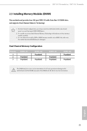
... into the slot at incorrect orientation. otherwise, this motherboard and DIMM may be damaged. For dual channel configuration, you force the DIMM into a DDR3 slot; Z87 OC Formula/ac / Z87 OC Formula 2.3 Installing Memory Modules (DIMM) This motherboard provides four 240-pin DDR3 (Double Data Rate 3) DIMM slots, and supports Dual Channel Memory Technology. 1.
... into the slot at incorrect orientation. otherwise, this motherboard and DIMM may be damaged. For dual channel configuration, you force the DIMM into a DDR3 slot; Z87 OC Formula/ac / Z87 OC Formula 2.3 Installing Memory Modules (DIMM) This motherboard provides four 240-pin DDR3 (Double Data Rate 3) DIMM slots, and supports Dual Channel Memory Technology. 1.

User Manual
Page 34
... system first, and then shut it down before you do not clear the CMOS right after you need to short pin2 and pin3 on the pins, the jumper is "Short". Please be noted that the password, date, time, and user default profile will be cleared only if the CMOS battery is.... 2.5 Jumpers Setup The illustration shows how jumpers are "Short" when a jumper cap is placed on these 2 pins. When the jumper cap is placed on CLRCMOS1 for 5 seconds. If no jumper cap is placed on the pins, the jumper is removed. The Clear CMOS Switch has the same function as the Clear CMOS...
... system first, and then shut it down before you do not clear the CMOS right after you need to short pin2 and pin3 on the pins, the jumper is "Short". Please be noted that the password, date, time, and user default profile will be cleared only if the CMOS battery is.... 2.5 Jumpers Setup The illustration shows how jumpers are "Short" when a jumper cap is placed on these 2 pins. When the jumper cap is placed on CLRCMOS1 for 5 seconds. If no jumper cap is placed on the pins, the jumper is removed. The Clear CMOS Switch has the same function as the Clear CMOS...
User Manual
Page 35
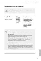
...to perform a normal restart. English 29 RESET (Reset Switch): Connect to this header, make sure the wire assignments and the pin assignments are NOT jumpers. Press the reset switch to restart the computer if the computer freezes and fails to turn off (S5... (System Power LED): Connect to the motherboard. HDLED (Hard Drive Activity LED): Connect to the pin assignments below. When connecting your system using the power switch. Z87 OC Formula/ac / Z87 OC Formula 2.6 Onboard Headers and Connectors Onboard headers and connectors are matched correctly. You may differ by chassis....
...to perform a normal restart. English 29 RESET (Reset Switch): Connect to this header, make sure the wire assignments and the pin assignments are NOT jumpers. Press the reset switch to restart the computer if the computer freezes and fails to turn off (S5... (System Power LED): Connect to the motherboard. HDLED (Hard Drive Activity LED): Connect to the pin assignments below. When connecting your system using the power switch. Z87 OC Formula/ac / Z87 OC Formula 2.6 Onboard Headers and Connectors Onboard headers and connectors are matched correctly. You may differ by chassis....
User Manual
Page 36
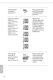
...) (see p.11 or 12, No. 33) (9-pin USB4_5) (see p.11 or 12, No. 36) USB_PWR PP+ GND DUMMY 1 GND P+ PUSB_PWR Besides two USB 2.0 ports... the system's power status. Each USB 2.0 header can support two ports. 30 English SATA3_A3_A4 SATA3_A1_A2 SATA3_0_1 SATA3_2_3 SATA3_4_5 Power LED Header (3-pin PLED1) (see p.11 or 12, No. 20) Please connect the chassis power LED to 6.0 Gb/s data transfer rate. These ... or 12, No. 21) (SATA3_A3_A4: see p.12, No. 17) 1 PLED- To minimize the boot time, use Intel® Z87 SATA ports (SATA3_0) for internal storage devices with up to this motherboard.
...) (see p.11 or 12, No. 33) (9-pin USB4_5) (see p.11 or 12, No. 36) USB_PWR PP+ GND DUMMY 1 GND P+ PUSB_PWR Besides two USB 2.0 ports... the system's power status. Each USB 2.0 header can support two ports. 30 English SATA3_A3_A4 SATA3_A1_A2 SATA3_0_1 SATA3_2_3 SATA3_4_5 Power LED Header (3-pin PLED1) (see p.11 or 12, No. 20) Please connect the chassis power LED to 6.0 Gb/s data transfer rate. These ... or 12, No. 21) (SATA3_A3_A4: see p.12, No. 17) 1 PLED- To minimize the boot time, use Intel® Z87 SATA ports (SATA3_0) for internal storage devices with up to this motherboard.
User Manual
Page 37
... USB 3.0 header can support two ports. If you use an AC'97 audio panel, please install it to OUT2_L. B. E. Z87 OC Formula/ac / Z87 OC Formula USB 3.0 Headers (19-pin USB3_8_9) (see p.11 or 12, No. 15) (19-pin USB3_10_11) (see p.11 or 12, No. 16) (USB3_12) (see p.11 or 12, No. 13) Vbus IntA_PA_SSRXIntA_PA_SSRX+ GND IntA_PA_SSTXIntA_PA_SSTX+ GND...
... USB 3.0 header can support two ports. If you use an AC'97 audio panel, please install it to OUT2_L. B. E. Z87 OC Formula/ac / Z87 OC Formula USB 3.0 Headers (19-pin USB3_8_9) (see p.11 or 12, No. 15) (19-pin USB3_10_11) (see p.11 or 12, No. 16) (USB3_12) (see p.11 or 12, No. 13) Vbus IntA_PA_SSRXIntA_PA_SSRX+ GND IntA_PA_SSTXIntA_PA_SSTX+ GND...

User Manual
Page 38
... CHA_FAN_SPEED FAN_SPEED_CONTROL Please connect fan cables to the fan connectors and match the black wire to Pin 1-3. If you plan to connect a 3-Pin CPU fan, please connect it along Pin 1 and Pin 13. English ATX Power Connector (24-pin ATXPWR1) (see p.11 or 12, No. 4) 4 3 21 GN D + 12V CPU_ ... This motherboard provides a 4-Pin CPU fan (Quiet Fan) connector. To use a 20-pin ATX power supply, please plug it to the ground pin. (3-pin CHA_FAN2) (see p.11 or 12, No. 34) (3-pin CHA_FAN3) (see p.11 or 12, No. 19) (3-pin CHA_FAN4) (see p.11 or 12, No. 42) (3-pin PWR_FAN1) (see p.11 ...
... CHA_FAN_SPEED FAN_SPEED_CONTROL Please connect fan cables to the fan connectors and match the black wire to Pin 1-3. If you plan to connect a 3-Pin CPU fan, please connect it along Pin 1 and Pin 13. English ATX Power Connector (24-pin ATXPWR1) (see p.11 or 12, No. 4) 4 3 21 GN D + 12V CPU_ ... This motherboard provides a 4-Pin CPU fan (Quiet Fan) connector. To use a 20-pin ATX power supply, please plug it to the ground pin. (3-pin CHA_FAN2) (see p.11 or 12, No. 34) (3-pin CHA_FAN3) (see p.11 or 12, No. 19) (3-pin CHA_FAN4) (see p.11 or 12, No. 42) (3-pin PWR_FAN1) (see p.11 ...
User Manual
Page 39
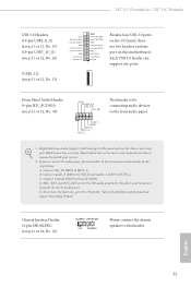
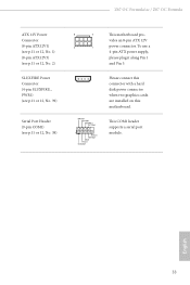
Z87 OC Formula/ac / Z87 OC Formula ATX 12V Power Connector (8-pin ATX12V1) (see p.11 or 12, No. 1) (8-pin ATX12V3) (see p.11 or 12, No. 2) SLI/XFIRE Power Connector (4-pin SLI/XFIRE_ PWR1) (see p.11 or 12, No. 39) Serial Port Header (9-pin COM1) (see p.11 or 12, No. 38) 8 5 This motherboard ...pro- This COM1 header supports a serial port module. To use a 4-pin ATX power supply, please plug it along Pin 1 and Pin 5. English 33 vides an 8-pin ATX 12V 4 1 power connector. RRXD1 DDTR#1 DDSR#1 CCTS#1 1 RRI#1 RRTS#1 GND TTXD1 DDCD#1 Please connect...
Z87 OC Formula/ac / Z87 OC Formula ATX 12V Power Connector (8-pin ATX12V1) (see p.11 or 12, No. 1) (8-pin ATX12V3) (see p.11 or 12, No. 2) SLI/XFIRE Power Connector (4-pin SLI/XFIRE_ PWR1) (see p.11 or 12, No. 39) Serial Port Header (9-pin COM1) (see p.11 or 12, No. 38) 8 5 This motherboard ...pro- This COM1 header supports a serial port module. To use a 4-pin ATX power supply, please plug it along Pin 1 and Pin 5. English 33 vides an 8-pin ATX 12V 4 1 power connector. RRXD1 DDTR#1 DDSR#1 CCTS#1 1 RRI#1 RRTS#1 GND TTXD1 DDCD#1 Please connect...

User Manual
Page 40
V-ProbeTM (7-pin VOL_ CON1, 7-pin VOL_ CON2) (see p.11 or 12, No. 11) IO GFX SA RING VCOMP CORE0 GND PCH_IREF VCOMP2 1.5VPCH 1.05PCH VCCM VCCin GND Users are able to measure onboard components voltage. PCH_IREF: PCH1.5V IREF voltage VCOMP2: CPU 2nd COMP voltage 1.5VPCH: PCH 1.5V voltage 1.05PCH: PCH 1.05V voltage VCCM: DRAM voltage VCC-in: CPU input voltage IO: CPU IO voltage GFX: CPU GFX (Graphics) voltage SA: CPU system agent voltage RING: CPU Ring (cache) voltage VCOMP: CPU COMP voltage CORE0: CPU CORE0 voltage English 34
V-ProbeTM (7-pin VOL_ CON1, 7-pin VOL_ CON2) (see p.11 or 12, No. 11) IO GFX SA RING VCOMP CORE0 GND PCH_IREF VCOMP2 1.5VPCH 1.05PCH VCCM VCCin GND Users are able to measure onboard components voltage. PCH_IREF: PCH1.5V IREF voltage VCOMP2: CPU 2nd COMP voltage 1.5VPCH: PCH 1.5V voltage 1.05PCH: PCH 1.05V voltage VCCM: DRAM voltage VCC-in: CPU input voltage IO: CPU IO voltage GFX: CPU GFX (Graphics) voltage SA: CPU system agent voltage RING: CPU Ring (cache) voltage VCOMP: CPU COMP voltage CORE0: CPU CORE0 voltage English 34

Quick Installation Guide
Page 3
Z87 OC Formula/ac / Z87 OC Formula Motherboard Layout Z87 OC Formula/ac 1 2 3 4 5 6 HDMI2 USB 3.0 T: USB0 B: USB1 HDMI1 USB 3.0 T: USB2 Top: RJ-45 B: USB3 44 USB 2.0 T: USB0 B: USB1 PS2 Keyboard /Mouse ATX12V1 ATX12V3 CPU_FAN1 CPU_FAN2 + 7 - 8 MENU 9 10 11 DDR3_A1 (64 bit, 240-pin module) DDR3_A2 (64 bit, 240-pin module) DDR3_B1 (64 bit, 240-pin module) DDR3_B2 (64 bit, 240-pin... 17 18 19 WiFi-802.11n Module MINI_PCIE1 20 PCIE2 Z87 OC Formula Intel 21 LAN PCIE3 CMOS CLRCMOS1 Battery 1 Z87 22 Purity RoHS SoundTM PCIE5 PCIE4 HD_AUDIO1 1 SLI/XFIRE_PWR1 ...
Z87 OC Formula/ac / Z87 OC Formula Motherboard Layout Z87 OC Formula/ac 1 2 3 4 5 6 HDMI2 USB 3.0 T: USB0 B: USB1 HDMI1 USB 3.0 T: USB2 Top: RJ-45 B: USB3 44 USB 2.0 T: USB0 B: USB1 PS2 Keyboard /Mouse ATX12V1 ATX12V3 CPU_FAN1 CPU_FAN2 + 7 - 8 MENU 9 10 11 DDR3_A1 (64 bit, 240-pin module) DDR3_A2 (64 bit, 240-pin module) DDR3_B1 (64 bit, 240-pin module) DDR3_B2 (64 bit, 240-pin... 17 18 19 WiFi-802.11n Module MINI_PCIE1 20 PCIE2 Z87 OC Formula Intel 21 LAN PCIE3 CMOS CLRCMOS1 Battery 1 Z87 22 Purity RoHS SoundTM PCIE5 PCIE4 HD_AUDIO1 1 SLI/XFIRE_PWR1 ...

Quick Installation Guide
Page 4
Z87 OC Formula 1 2 3 4 5 6 HDMI2 USB 3.0 T: USB0 B: USB1 HDMI1 USB 3.0 T: USB2 Top: RJ-45 B: USB3 44 USB 2.0 T: USB0 B: USB1 PS2 Keyboard /Mouse ATX12V1 ATX12V3 CPU_FAN1 CPU_FAN2 + 7 - 8 MENU 9 10 11 DDR3_A1 (64 bit, 240-pin module) DDR3_A2 (64 bit, 240-pin module) DDR3_B1 (64 bit, 240-pin module) DDR3_B2 (64 bit, 240-pin...14 15 16 17 18 19 MINI_PCIE1 SATA3_A3_A4 SATA3_A1_A2 SATA3_0_1 SATA3_2_3 SATA3_4_5 20 PCIE2 Z87 OC Formula Intel 21 LAN PCIE3 CMOS CLRCMOS1 Battery 1 Z87 22 Purity RoHS SoundTM PCIE5 PCIE4 HD_AUDIO1 1 SLI/XFIRE_PWR1 PCIE6 COM1 1 ...
Z87 OC Formula 1 2 3 4 5 6 HDMI2 USB 3.0 T: USB0 B: USB1 HDMI1 USB 3.0 T: USB2 Top: RJ-45 B: USB3 44 USB 2.0 T: USB0 B: USB1 PS2 Keyboard /Mouse ATX12V1 ATX12V3 CPU_FAN1 CPU_FAN2 + 7 - 8 MENU 9 10 11 DDR3_A1 (64 bit, 240-pin module) DDR3_A2 (64 bit, 240-pin module) DDR3_B1 (64 bit, 240-pin module) DDR3_B2 (64 bit, 240-pin...14 15 16 17 18 19 MINI_PCIE1 SATA3_A3_A4 SATA3_A1_A2 SATA3_0_1 SATA3_2_3 SATA3_4_5 20 PCIE2 Z87 OC Formula Intel 21 LAN PCIE3 CMOS CLRCMOS1 Battery 1 Z87 22 Purity RoHS SoundTM PCIE5 PCIE4 HD_AUDIO1 1 SLI/XFIRE_PWR1 PCIE6 COM1 1 ...

Quick Installation Guide
Page 5
... 12V Power Connector (ATX12V1) 2 ATX 12V Power Connector (ATX12V3) 3 CPU Fan Connector (CPU_FAN1) 4 CPU Fan Connector (CPU_FAN2) 5 2 x 240-pin DDR3 DIMM Slots (DDR3_A1, DDR3_B1) 6 2 x 240-pin DDR3 DIMM Slots (DDR3_A2, DDR3_B2) 7 Rapid OC Button (+) 8 Rapid OC Button (-) 9 Menu Button (MENU1) 10 Post Status Checker (PSC) 11 V-ProbeTM (VOL_CON1, VOL_CON2) 12 ATX Power Connector (ATXPWR1...) 28 Power Switch (PWRBTN1) 29 Reset Switch (RSTBTN1) 30 Clear CMOS Switch 31 Status OLED 32 BIOS Selection Switch (BIOS_SEL1) 33 USB 2.0 Header (USB2_3) 3 English Z87 OC Formula/ac / Z87 OC Formula No.
... 12V Power Connector (ATX12V1) 2 ATX 12V Power Connector (ATX12V3) 3 CPU Fan Connector (CPU_FAN1) 4 CPU Fan Connector (CPU_FAN2) 5 2 x 240-pin DDR3 DIMM Slots (DDR3_A1, DDR3_B1) 6 2 x 240-pin DDR3 DIMM Slots (DDR3_A2, DDR3_B2) 7 Rapid OC Button (+) 8 Rapid OC Button (-) 9 Menu Button (MENU1) 10 Post Status Checker (PSC) 11 V-ProbeTM (VOL_CON1, VOL_CON2) 12 ATX Power Connector (ATXPWR1...) 28 Power Switch (PWRBTN1) 29 Reset Switch (RSTBTN1) 30 Clear CMOS Switch 31 Status OLED 32 BIOS Selection Switch (BIOS_SEL1) 33 USB 2.0 Header (USB2_3) 3 English Z87 OC Formula/ac / Z87 OC Formula No.

Quick Installation Guide
Page 10
... • Home Cloud • Conformal Coating • Purity SoundTM • 802.11ac WiFi (for Z87 OC Formula/ac only) • HDMI-In OC Formula Kit OC Formula Power Kit • 12 Power Phase Design • Digi Power • Dual-Stack MOSFET (DSM...compare to iron powder choke) OC Formula Connector Kit • Hi-Density Power Connector (8 pin) • 15μGold Finger (CPU sockets, memory sockets and PCIE x16 slots) • Distortion-Free Slot OC Formula Cooling Kit • Twin... • Supports Intel® K-Series unlocked CPU • Supports ASRock BCLK Full-range Overclocking
... • Home Cloud • Conformal Coating • Purity SoundTM • 802.11ac WiFi (for Z87 OC Formula/ac only) • HDMI-In OC Formula Kit OC Formula Power Kit • 12 Power Phase Design • Digi Power • Dual-Stack MOSFET (DSM...compare to iron powder choke) OC Formula Connector Kit • Hi-Density Power Connector (8 pin) • 15μGold Finger (CPU sockets, memory sockets and PCIE x16 slots) • Distortion-Free Slot OC Formula Cooling Kit • Twin... • Supports Intel® K-Series unlocked CPU • Supports ASRock BCLK Full-range Overclocking

Quick Installation Guide
Page 13
ment 11 English Z87 OC Formula/ac / Z87 OC Formula Storage • 6 x SATA3 6.0 Gb/s connectors by Intel® Z87, support RAID (RAID 0, RAID 1, RAID 5, RAID 10, Intel Rapid Storage Technology 12 and Intel Smart ... header • 1 x Power LED header • 2 x CPU Fan connectors (1 x 4-pin, 1 x 3-pin) • 4 x Chassis Fan connectors (1 x 4-pin, 3 x 3-pin) • 1 x Power Fan connector (3-pin) • 1 x MOS Fan connector (3-pin) • 1 x 24 pin ATX power connector • 2 x 8 pin 12V power connectors (Hi-Density Power Connec- tor) • 1 x SLI/XFire power connector ...
ment 11 English Z87 OC Formula/ac / Z87 OC Formula Storage • 6 x SATA3 6.0 Gb/s connectors by Intel® Z87, support RAID (RAID 0, RAID 1, RAID 5, RAID 10, Intel Rapid Storage Technology 12 and Intel Smart ... header • 1 x Power LED header • 2 x CPU Fan connectors (1 x 4-pin, 1 x 3-pin) • 4 x Chassis Fan connectors (1 x 4-pin, 3 x 3-pin) • 1 x Power Fan connector (3-pin) • 1 x MOS Fan connector (3-pin) • 1 x 24 pin ATX power connector • 2 x 8 pin 12V power connectors (Hi-Density Power Connec- tor) • 1 x SLI/XFire power connector ...


