User Manual
Page 7
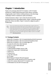
Z87 OC Formula/ac / Z87 OC Formula Chapter 1 Introduction Thank you for specific information about the model you require technical support related to change without further notice. It delivers excellent performance with robust design conforming to ASRock's commitment to 1 Power Cables (Optional) • 1 x I/O Panel Shield • 1 x ASRock Flexible SLI Bridge Connector Cable • 1 x Front USB 3.0 Panel with 2.5" HDD/SSD Rack •...
Z87 OC Formula/ac / Z87 OC Formula Chapter 1 Introduction Thank you for specific information about the model you require technical support related to change without further notice. It delivers excellent performance with robust design conforming to ASRock's commitment to 1 Power Cables (Optional) • 1 x I/O Panel Shield • 1 x ASRock Flexible SLI Bridge Connector Cable • 1 x Front USB 3.0 Panel with 2.5" HDD/SSD Rack •...

User Manual
Page 8
...; 802.11ac WiFi (for Z87 OC Formula/ac only) • HDMI-In OC Formula Kit OC Formula Power Kit • 12 Power Phase Design • Digi Power • Dual-Stack MOSFET ... loss compare to iron powder choke) OC Formula Connector Kit • Hi-Density Power Connector (8 pin) • 15μGold...OC Formula Cooling Kit • Twin-Power Cooling (Combine active air cooling and water cooling) • 8 Layer PCB • 4 x 2oz copper • GELID Solutions GC-Extreme Thermal Compound OC Formula...8226; 12 Power Phase Design • Supports Intel® Turbo Boost 2.0 Technology • Supports ...
...; 802.11ac WiFi (for Z87 OC Formula/ac only) • HDMI-In OC Formula Kit OC Formula Power Kit • 12 Power Phase Design • Digi Power • Dual-Stack MOSFET ... loss compare to iron powder choke) OC Formula Connector Kit • Hi-Density Power Connector (8 pin) • 15μGold...OC Formula Cooling Kit • Twin-Power Cooling (Combine active air cooling and water cooling) • 8 Layer PCB • 4 x 2oz copper • GELID Solutions GC-Extreme Thermal Compound OC Formula...8226; 12 Power Phase Design • Supports Intel® Turbo Boost 2.0 Technology • Supports ...
User Manual
Page 11
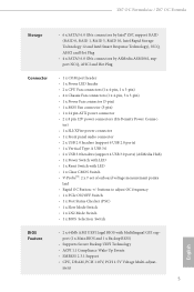
...OC Button: +/- Z87 OC Formula/ac / Z87 OC Formula Storage • 6 x SATA3 6.0 Gb/s connectors by Intel® Z87, support RAID (RAID 0, RAID 1, RAID 5, RAID 10, Intel Rapid Storage Technology 12 and Intel Smart Response Technology), NCQ, AHCI and Hot Plug • 4 x SATA3 6.0 Gb/s connectors by ASMedia ASM1061, support NCQ, AHCI and Hot Plug Connector • 1 x COM port header • 1 x Power... 3.0 • 2 x USB 3.0 headers (support 4 USB 3.0 ports) (ASMedia Hub) • 1 x Power Switch with LED • 1 x Reset Switch with Multilingual GUI support (1 x Main BIOS and 1 x Backup...
...OC Button: +/- Z87 OC Formula/ac / Z87 OC Formula Storage • 6 x SATA3 6.0 Gb/s connectors by Intel® Z87, support RAID (RAID 0, RAID 1, RAID 5, RAID 10, Intel Rapid Storage Technology 12 and Intel Smart Response Technology), NCQ, AHCI and Hot Plug • 4 x SATA3 6.0 Gb/s connectors by ASMedia ASM1061, support NCQ, AHCI and Hot Plug Connector • 1 x COM port header • 1 x Power... 3.0 • 2 x USB 3.0 headers (support 4 USB 3.0 ports) (ASMedia Hub) • 1 x Power Switch with LED • 1 x Reset Switch with Multilingual GUI support (1 x Main BIOS and 1 x Backup...
User Manual
Page 12
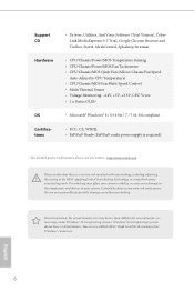
...; FCC, CE, WHQL • ErP/EuP Ready (ErP/EuP ready power supply is required) * For detailed product information, please visit our website: http://www.asrock.com Please realize that Windows® cannot use ASRock XFast RAM to limitation, the actual memory size may affect your system's...Version), CyberLink MediaEspresso 6.5 Trial, Google Chrome Browser and Toolbar, Start8, MeshCentral, Splashtop Streamer • CPU/Chassis/Power/MOS Temperature Sensing • CPU/Chassis/Power/MOS Fan Tachometer • CPU/Chassis/MOS Quiet Fan (Allows Chassis Fan Speed Auto-Adjust by overclocking.
...; FCC, CE, WHQL • ErP/EuP Ready (ErP/EuP ready power supply is required) * For detailed product information, please visit our website: http://www.asrock.com Please realize that Windows® cannot use ASRock XFast RAM to limitation, the actual memory size may affect your system's...Version), CyberLink MediaEspresso 6.5 Trial, Google Chrome Browser and Toolbar, Start8, MeshCentral, Splashtop Streamer • CPU/Chassis/Power/MOS Temperature Sensing • CPU/Chassis/Power/MOS Fan Tachometer • CPU/Chassis/MOS Quiet Fan (Allows Chassis Fan Speed Auto-Adjust by overclocking.

User Manual
Page 13
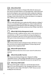
... BIOS in a few clicks without preparing an additional floppy diskette or other complicated flash utility. ASRock APP Charger allows you to RAM (S3), hibernation mode (S4) or power off (S5). LAN Application Prioritization: You can boost the performance of your application's priority ideally... that the USB flash drive or hard drive must use FAT32/16/12 file system. Z87 OC Formula/ac / Z87 OC Formula 1.3 Unique Features ASRock Formula Drive Formula Drive is a BIOS flash utility embedded in games. ASRock APP Charger Simply by pressing or during POST to enter the BIOS setup menu to 40...
... BIOS in a few clicks without preparing an additional floppy diskette or other complicated flash utility. ASRock APP Charger allows you to RAM (S3), hibernation mode (S4) or power off (S5). LAN Application Prioritization: You can boost the performance of your application's priority ideally... that the USB flash drive or hard drive must use FAT32/16/12 file system. Z87 OC Formula/ac / Z87 OC Formula 1.3 Unique Features ASRock Formula Drive Formula Drive is a BIOS flash utility embedded in games. ASRock APP Charger Simply by pressing or during POST to enter the BIOS setup menu to 40...
User Manual
Page 14
... "RAID", then you can help you without permission to modify the system time are able to dehumidify the system after regaining power. ASRock XFast RAM ASRock XFast RAM is that it also boosts the speed of Adobe Photoshop 5 times faster. Another advantage of previously visited websites,... making web surfing faster than ever. If power loss occurs during the BIOS updating process, ASRock Crashless BIOS will power on automatically to establish an internet curfew or restrict internet access at specified times via OMG...
... "RAID", then you can help you without permission to modify the system time are able to dehumidify the system after regaining power. ASRock XFast RAM ASRock XFast RAM is that it also boosts the speed of Adobe Photoshop 5 times faster. Another advantage of previously visited websites,... making web surfing faster than ever. If power loss occurs during the BIOS updating process, ASRock Crashless BIOS will power on automatically to establish an internet curfew or restrict internet access at specified times via OMG...
User Manual
Page 16
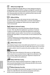
... OLED screen. You will automatically shift to toggle between information of the power on self test, debug codes, the current time, temperatures, frequencies and voltages of various points on . ASRock Home Cloud This motherboard supports remote wake with the onboard Intel LAN, .... Status OLED Status OLED shows various information of Conformal Coating on contact. ASRock Conformal Coating Conductive liquids such as former designs, but only to log in Formula Drive. ASRock FAN-Tastic Tuning ASRock FAN-Tastic Tuning is money, why waste precious time everyday typing usernames to...
... OLED screen. You will automatically shift to toggle between information of the power on self test, debug codes, the current time, temperatures, frequencies and voltages of various points on . ASRock Home Cloud This motherboard supports remote wake with the onboard Intel LAN, .... Status OLED Status OLED shows various information of Conformal Coating on contact. ASRock Conformal Coating Conductive liquids such as former designs, but only to log in Formula Drive. ASRock FAN-Tastic Tuning ASRock FAN-Tastic Tuning is money, why waste precious time everyday typing usernames to...
User Manual
Page 17
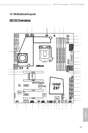
Z87 OC Formula/ac / Z87 OC Formula 1.4 Motherboard Layout Z87 OC Formula/ac 1 2 3 4 5 6 HDMI2 USB 3.0 T: USB0 B: USB1 HDMI1 USB 3.0 T: USB2 Top: RJ-45 B: USB3 44 USB 2.0 T: USB0 B: USB1 PS2 Keyboard /Mouse ATX12V1 ATX12V3 ... MINI_PCIE1 20 PCIE2 Z87 OC Formula Intel 21 LAN PCIE3 CMOS CLRCMOS1 Battery 1 Z87 22 Purity RoHS SoundTM PCIE5 PCIE4 HD_AUDIO1 1 SLI/XFIRE_PWR1 PCIE6 COM1 1 Super I/O CHA_FAN1 USB4_5 1 CHA_FAN2 USB2_3 1 Status OLED BIOS_SEL1 A B CLRCBTN2 64Mb BIOS BIOS_B 64Mb BIOS BIOS_A BIOS_B_LED BIOS_A_LED Reset Power SPEAKER1 1 PLED1 ...
Z87 OC Formula/ac / Z87 OC Formula 1.4 Motherboard Layout Z87 OC Formula/ac 1 2 3 4 5 6 HDMI2 USB 3.0 T: USB0 B: USB1 HDMI1 USB 3.0 T: USB2 Top: RJ-45 B: USB3 44 USB 2.0 T: USB0 B: USB1 PS2 Keyboard /Mouse ATX12V1 ATX12V3 ... MINI_PCIE1 20 PCIE2 Z87 OC Formula Intel 21 LAN PCIE3 CMOS CLRCMOS1 Battery 1 Z87 22 Purity RoHS SoundTM PCIE5 PCIE4 HD_AUDIO1 1 SLI/XFIRE_PWR1 PCIE6 COM1 1 Super I/O CHA_FAN1 USB4_5 1 CHA_FAN2 USB2_3 1 Status OLED BIOS_SEL1 A B CLRCBTN2 64Mb BIOS BIOS_B 64Mb BIOS BIOS_A BIOS_B_LED BIOS_A_LED Reset Power SPEAKER1 1 PLED1 ...

User Manual
Page 18
Z87 OC Formula 1 2 3 4 5 6 HDMI2 USB 3.0 T: USB0 B: USB1 HDMI1 USB 3.0 T: USB2 Top: RJ-45 B: USB3 44 USB 2.0 T: USB0 B: USB1 PS2 Keyboard /Mouse ATX12V1 ATX12V3 CPU_FAN1 CPU_FAN2 + 7 ...SATA3_A1_A2 SATA3_0_1 SATA3_2_3 SATA3_4_5 20 PCIE2 Z87 OC Formula Intel 21 LAN PCIE3 CMOS CLRCMOS1 Battery 1 Z87 22 Purity RoHS SoundTM PCIE5 PCIE4 HD_AUDIO1 1 SLI/XFIRE_PWR1 PCIE6 COM1 1 Super I/O CHA_FAN1 USB4_5 1 CHA_FAN2 USB2_3 1 Status OLED BIOS_SEL1 A B CLRCBTN2 64Mb BIOS BIOS_B 64Mb BIOS BIOS_A BIOS_B_LED BIOS_A_LED Reset Power SPEAKER1 1 PLED1 1 PANEL1 ...
Z87 OC Formula 1 2 3 4 5 6 HDMI2 USB 3.0 T: USB0 B: USB1 HDMI1 USB 3.0 T: USB2 Top: RJ-45 B: USB3 44 USB 2.0 T: USB0 B: USB1 PS2 Keyboard /Mouse ATX12V1 ATX12V3 CPU_FAN1 CPU_FAN2 + 7 ...SATA3_A1_A2 SATA3_0_1 SATA3_2_3 SATA3_4_5 20 PCIE2 Z87 OC Formula Intel 21 LAN PCIE3 CMOS CLRCMOS1 Battery 1 Z87 22 Purity RoHS SoundTM PCIE5 PCIE4 HD_AUDIO1 1 SLI/XFIRE_PWR1 PCIE6 COM1 1 Super I/O CHA_FAN1 USB4_5 1 CHA_FAN2 USB2_3 1 Status OLED BIOS_SEL1 A B CLRCBTN2 64Mb BIOS BIOS_B 64Mb BIOS BIOS_A BIOS_B_LED BIOS_A_LED Reset Power SPEAKER1 1 PLED1 1 PANEL1 ...

User Manual
Page 19
...Slots (DDR3_A1, DDR3_B1) 6 2 x 240-pin DDR3 DIMM Slots (DDR3_A2, DDR3_B2) 7 Rapid OC Button (+) 8 Rapid OC Button (-) 9 Menu Button (MENU1) 10 Post Status Checker (PSC) 11 V-ProbeTM (VOL_CON1, VOL_CON2) 12 ATX Power Connector (ATXPWR1) 13 Vertical Type A USB 3.0 (USB3_12) 14 PCIe ON/OFF Switch 15 USB...Chassis Speaker Header (SPEAKER1) 26 Power LED Header (PLED1) 27 System Panel Header (PANEL1) 28 Power Switch (PWRBTN1) 29 Reset Switch (RSTBTN1) 30 Clear CMOS Switch 31 Status OLED 32 BIOS Selection Switch (BIOS_SEL1) 33 USB 2.0 Header (USB2_3) 13 English Z87 OC Formula/ac / Z87 OC Formula No.
...Slots (DDR3_A1, DDR3_B1) 6 2 x 240-pin DDR3 DIMM Slots (DDR3_A2, DDR3_B2) 7 Rapid OC Button (+) 8 Rapid OC Button (-) 9 Menu Button (MENU1) 10 Post Status Checker (PSC) 11 V-ProbeTM (VOL_CON1, VOL_CON2) 12 ATX Power Connector (ATXPWR1) 13 Vertical Type A USB 3.0 (USB3_12) 14 PCIe ON/OFF Switch 15 USB...Chassis Speaker Header (SPEAKER1) 26 Power LED Header (PLED1) 27 System Panel Header (PANEL1) 28 Power Switch (PWRBTN1) 29 Reset Switch (RSTBTN1) 30 Clear CMOS Switch 31 Status OLED 32 BIOS Selection Switch (BIOS_SEL1) 33 USB 2.0 Header (USB2_3) 13 English Z87 OC Formula/ac / Z87 OC Formula No.

User Manual
Page 20
No. Description 34 Chassis Fan Connector (CHA_FAN2) 35 Clear CMOS Jumper (CLRCMOS1) 36 USB 2.0 Header (USB4_5) 37 Chassis Fan Connector (CHA_FAN1) 38 COM Port Header (COM1) 39 SLI/XFIRE Power Connector (SLI/XFIRE_PWR1) 40 Front Panel Audio Header (HD_AUDIO1) 41 Power Fan Connector (PWR_FAN1) 42 Chassis Fan Connector (CHA_FAN4) 43 MOS Fan Connector (MOS_FAN1) 44 Twin-Power Cooling 14 English
No. Description 34 Chassis Fan Connector (CHA_FAN2) 35 Clear CMOS Jumper (CLRCMOS1) 36 USB 2.0 Header (USB4_5) 37 Chassis Fan Connector (CHA_FAN1) 38 COM Port Header (COM1) 39 SLI/XFIRE Power Connector (SLI/XFIRE_PWR1) 40 Front Panel Audio Header (HD_AUDIO1) 41 Power Fan Connector (PWR_FAN1) 42 Chassis Fan Connector (CHA_FAN4) 43 MOS Fan Connector (MOS_FAN1) 44 Twin-Power Cooling 14 English

User Manual
Page 23
...power consumption for WiFi 802.11 a/b/g/n/ac connectivity standards and Bluetooth v4.0. The 2T2R WiFi solution sets a WiFi high speed standard and offers max link rate up to 867Mbps. * The transmission speed may vary according to support WiFi + BT. Z87 OC Formula/ac / Z87 OC Formula 1.6 WiFi-802.11n Module and ASRock WiFi 2.4GHz Antenna (for Z87 OC Formula/ac... only ) WiFi + BT Module This motherboard comes with an exclusive WiFi 802.11 a/b/g/n/ac + BT v4.0 module...
...power consumption for WiFi 802.11 a/b/g/n/ac connectivity standards and Bluetooth v4.0. The 2T2R WiFi solution sets a WiFi high speed standard and offers max link rate up to 867Mbps. * The transmission speed may vary according to support WiFi + BT. Z87 OC Formula/ac / Z87 OC Formula 1.6 WiFi-802.11n Module and ASRock WiFi 2.4GHz Antenna (for Z87 OC Formula/ac... only ) WiFi + BT Module This motherboard comes with an exclusive WiFi 802.11 a/b/g/n/ac + BT v4.0 module...
User Manual
Page 26
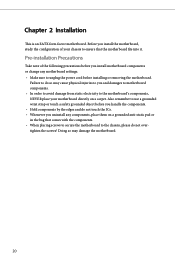
... a safety grounded object before you handle the components. • Hold components by the edges and do not overtighten the screws! Also remember to unplug the power cord before you uninstall any components, place them on a carpet. Pre-installation Precautions Take note of your motherboard directly on a grounded anti-static pad or...
... a safety grounded object before you handle the components. • Hold components by the edges and do not overtighten the screws! Also remember to unplug the power cord before you uninstall any components, place them on a carpet. Pre-installation Precautions Take note of your motherboard directly on a grounded anti-static pad or...

User Manual
Page 27
Otherwise, the CPU will be seriously damaged. 2. Unplug all power cables before installing the CPU. 1 A B 2 21 English Z87 OC Formula/ac / Z87 OC Formula 2.1 Installing the CPU 1. Before you insert the 1150-Pin CPU into the socket if above situation is unclean, or if there are any bent pins in the socket. Do not force to insert the CPU into the socket, please check if the PnP cap is on the socket, if the CPU surface is found.
Otherwise, the CPU will be seriously damaged. 2. Unplug all power cables before installing the CPU. 1 A B 2 21 English Z87 OC Formula/ac / Z87 OC Formula 2.1 Installing the CPU 1. Before you insert the 1150-Pin CPU into the socket if above situation is unclean, or if there are any bent pins in the socket. Do not force to insert the CPU into the socket, please check if the PnP cap is on the socket, if the CPU surface is found.
User Manual
Page 33
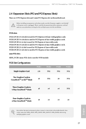
Please read the documentation of the expansion card and make sure that the power supply is switched off or the power cord is used for the card before you start the installation. PCIE5 (PCIE 2.0 x1 slot) is used for PCI Express x16 lane width ... for PCI Express x8 lane width graphics cards. mini-PCIe slots: MINI_PCIE1 (mini-PCIe slot) is used for PCI Express x4 lane width graphics cards. Z87 OC Formula/ac / Z87 OC Formula 2.4 Expansion Slots (PCI and PCI Express Slots) There are 6 PCI Express slots and 1 mini-PCI Express slot on the motherboard. PCIE4 (PCIE 3.0 x16 ...
Please read the documentation of the expansion card and make sure that the power supply is switched off or the power cord is used for the card before you start the installation. PCIE5 (PCIE 2.0 x1 slot) is used for PCI Express x16 lane width ... for PCI Express x8 lane width graphics cards. mini-PCIe slots: MINI_PCIE1 (mini-PCIe slot) is used for PCI Express x4 lane width graphics cards. Z87 OC Formula/ac / Z87 OC Formula 2.4 Expansion Slots (PCI and PCI Express Slots) There are 6 PCI Express slots and 1 mini-PCI Express slot on the motherboard. PCIE4 (PCIE 3.0 x16 ...

User Manual
Page 34
... the pins, the jumper is "Open". After waiting for 15 seconds, use a jumper cap to default setup, please turn off the computer and unplug the power cord from the power supply. When the jumper cap is placed on the pins, the jumper is "Short". English 28
... the pins, the jumper is "Open". After waiting for 15 seconds, use a jumper cap to default setup, please turn off the computer and unplug the power cord from the power supply. When the jumper cap is placed on the pins, the jumper is "Short". English 28
User Manual
Page 35
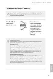
... S1/S3 sleep state. HDLED (Hard Drive Activity LED): Connect to perform a normal restart. When connecting your system using the power switch. Do NOT place jumper caps over the headers and connectors will cause permanent damage to the pin assignments below. You may ...chassis front panel. PLED (System Power LED): Connect to turn off (S5). The front panel design may configure the way to the power status indicator on the chassis front panel. English 29 Placing jumper caps over these headers and connectors. Z87 OC Formula/ac / Z87 OC Formula 2.6 Onboard Headers and Connectors Onboard...
... S1/S3 sleep state. HDLED (Hard Drive Activity LED): Connect to perform a normal restart. When connecting your system using the power switch. Do NOT place jumper caps over the headers and connectors will cause permanent damage to the pin assignments below. You may ...chassis front panel. PLED (System Power LED): Connect to turn off (S5). The front panel design may configure the way to the power status indicator on the chassis front panel. English 29 Placing jumper caps over these headers and connectors. Z87 OC Formula/ac / Z87 OC Formula 2.6 Onboard Headers and Connectors Onboard...
User Manual
Page 36
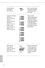
... DUMMY 1 GND P+ PUSB_PWR Besides two USB 2.0 ports on the I/O panel, there are two headers on this header to indicate the system's power status. These ten SATA3 connectors support SATA data cables for your bootable devices. PLED+ PLED+ Serial ATA3 Connectors (SATA3_0_1: see p.11 or 12...p.12, No. 17) 1 PLED- SATA3_A3_A4 SATA3_A1_A2 SATA3_0_1 SATA3_2_3 SATA3_4_5 Power LED Header (3-pin PLED1) (see p.11 or 12, No. 20) Please connect the chassis power LED to this motherboard. To minimize the boot time, use Intel® Z87 SATA ports (SATA3_0) for internal storage devices with up to 6.0...
... DUMMY 1 GND P+ PUSB_PWR Besides two USB 2.0 ports on the I/O panel, there are two headers on this header to indicate the system's power status. These ten SATA3 connectors support SATA data cables for your bootable devices. PLED+ PLED+ Serial ATA3 Connectors (SATA3_0_1: see p.11 or 12...p.12, No. 17) 1 PLED- SATA3_A3_A4 SATA3_A1_A2 SATA3_0_1 SATA3_2_3 SATA3_4_5 Power LED Header (3-pin PLED1) (see p.11 or 12, No. 20) Please connect the chassis power LED to this motherboard. To minimize the boot time, use Intel® Z87 SATA ports (SATA3_0) for internal storage devices with up to 6.0...

User Manual
Page 38
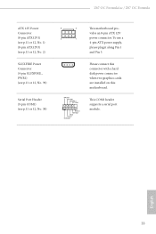
...12, No. 3) (3-pin CPU_FAN2) (see p.11 or 12, No. 12) 32 12 24 1 13 This motherboard provides a 24-pin ATX power connector. If you plan to Pin 1-3. ATX Power Connector (24-pin ATXPWR1) (see p.11 or 12, No. 4) 4 3 21 GN D + 12V CPU_ FAN_SPEED FAN_SPEED_CONTROL GND +12V CPU_FAN_SPEED This ...motherboard provides a 4-Pin CPU fan (Quiet Fan) connector. To use a 20-pin ATX power supply, please plug it to connect a 3-Pin CPU...
...12, No. 3) (3-pin CPU_FAN2) (see p.11 or 12, No. 12) 32 12 24 1 13 This motherboard provides a 24-pin ATX power connector. If you plan to Pin 1-3. ATX Power Connector (24-pin ATXPWR1) (see p.11 or 12, No. 4) 4 3 21 GN D + 12V CPU_ FAN_SPEED FAN_SPEED_CONTROL GND +12V CPU_FAN_SPEED This ...motherboard provides a 4-Pin CPU fan (Quiet Fan) connector. To use a 20-pin ATX power supply, please plug it to connect a 3-Pin CPU...
User Manual
Page 39
... DDTR#1 DDSR#1 CCTS#1 1 RRI#1 RRTS#1 GND TTXD1 DDCD#1 Please connect this connector with a hard disk power connector when two graphics cards are installed on this motherboard. Z87 OC Formula/ac / Z87 OC Formula ATX 12V Power Connector (8-pin ATX12V1) (see p.11 or 12, No. 1) (8-pin ATX12V3) (see p.11 or 12,... No. 2) SLI/XFIRE Power Connector (4-pin SLI/XFIRE_ PWR1) (see p.11 or 12, No. 39) Serial ...
... DDTR#1 DDSR#1 CCTS#1 1 RRI#1 RRTS#1 GND TTXD1 DDCD#1 Please connect this connector with a hard disk power connector when two graphics cards are installed on this motherboard. Z87 OC Formula/ac / Z87 OC Formula ATX 12V Power Connector (8-pin ATX12V1) (see p.11 or 12, No. 1) (8-pin ATX12V3) (see p.11 or 12,... No. 2) SLI/XFIRE Power Connector (4-pin SLI/XFIRE_ PWR1) (see p.11 or 12, No. 39) Serial ...

