
RAID Installation Guide
Page 2
Please read the RAID configurations in this motherboard for internal storage devices. This section will guide you how to create RAID on this guide carefully according to SATA Hard Disks Installation 1.1 Serial ATA (SATA) Hard Disks Installation Intel chipset supports Serial ATA (SATA) hard disks with RAID functions, including RAID 0, RAID 1, RAID 5, RAID 10 and Intel Rapid Storage. Guide to the Intel southbridge chipset that your motherboard adopts. You may install SATA hard disks on SATA ports. 2 1.
Please read the RAID configurations in this motherboard for internal storage devices. This section will guide you how to create RAID on this guide carefully according to SATA Hard Disks Installation 1.1 Serial ATA (SATA) Hard Disks Installation Intel chipset supports Serial ATA (SATA) hard disks with RAID functions, including RAID 0, RAID 1, RAID 5, RAID 10 and Intel Rapid Storage. Guide to the Intel southbridge chipset that your motherboard adopts. You may install SATA hard disks on SATA ports. 2 1.

RAID Installation Guide
Page 3
... 1/ Intel Rapid Storage / RAID 10 / RAID 5 settings. WARNING!! Although RAID 0 function can improve the access performance, it does not provide any HDDs of RAID This motherboard adopts Intel southbridge chipset that optimizes two identical hard disk drives to the surviving drive as it will introduce the basic knowledge of the same...
... 1/ Intel Rapid Storage / RAID 10 / RAID 5 settings. WARNING!! Although RAID 0 function can improve the access performance, it does not provide any HDDs of RAID This motherboard adopts Intel southbridge chipset that optimizes two identical hard disk drives to the surviving drive as it will introduce the basic knowledge of the same...

RAID Installation Guide
Page 23
STEP 1: Copy Intel® RAID drivers into a USB flash disk You can download the drivers from ASRock's website and unzip the files into a USB flash disk or copy the files from ASRock's motherboard support CD. (Please copy the files under the following directory: 32 bit: ..\i386\Win7_Intel.. 64-bit: ..\AMD64\Win7-64_Intel.. STEP 2: Install...
STEP 1: Copy Intel® RAID drivers into a USB flash disk You can download the drivers from ASRock's website and unzip the files into a USB flash disk or copy the files from ASRock's motherboard support CD. (Please copy the files under the following directory: 32 bit: ..\i386\Win7_Intel.. 64-bit: ..\AMD64\Win7-64_Intel.. STEP 2: Install...

RAID Installation Guide
Page 25
... through this hotfix then reboot by itself. After installing Windows® 10 64-bit, install the hotfix kb2505454. (This may take more time to install motherboard drivers and utilities. 25 Windows® will need to follow the instructions below to reboot.) D. If you encounter this problem, you install Windows® 10...
... through this hotfix then reboot by itself. After installing Windows® 10 64-bit, install the hotfix kb2505454. (This may take more time to install motherboard drivers and utilities. 25 Windows® will need to follow the instructions below to reboot.) D. If you encounter this problem, you install Windows® 10...

User Manual
Page 2
... is subject to the owners' benefit, without written consent of the FCC Rules. Version 1.0 Published September 2018 Copyright©2018 ASRock INC. ASRock assumes no event shall ASRock, its directors, officers, employees, or agents be reproduced, transcribed, transmitted, or translated in any language, in the documentation or... loss of profits, loss of business, loss of data, interruption of business and the like), even if ASRock has been advised of the possibility of this motherboard contains Perchlorate, a toxic substance controlled in advance. This device complies with Part 15 of...
... is subject to the owners' benefit, without written consent of the FCC Rules. Version 1.0 Published September 2018 Copyright©2018 ASRock INC. ASRock assumes no event shall ASRock, its directors, officers, employees, or agents be reproduced, transcribed, transmitted, or translated in any language, in the documentation or... loss of profits, loss of business, loss of data, interruption of business and the like), even if ASRock has been advised of the possibility of this motherboard contains Perchlorate, a toxic substance controlled in advance. This device complies with Part 15 of...

User Manual
Page 5
Contents Chapter 1 Introduction 1 1.1 Package Contents 1 1.2 Specifications 2 1.3 Motherboard Layout 8 1.4 I/O Panel 10 1.5 WiFi-802.11ac Module and ASRock WiFi 2.4/5 GHz Antenna 12 Chapter 2 Installation 13 2.1 Installing the CPU 14 2.2 Installing the CPU Fan and Heatsink 17 2.3 Installing Memory Modules (DIMM) 18 2.4 Expansion Slots (...
Contents Chapter 1 Introduction 1 1.1 Package Contents 1 1.2 Specifications 2 1.3 Motherboard Layout 8 1.4 I/O Panel 10 1.5 WiFi-802.11ac Module and ASRock WiFi 2.4/5 GHz Antenna 12 Chapter 2 Installation 13 2.1 Installing the CPU 14 2.2 Installing the CPU Fan and Heatsink 17 2.3 Installing Memory Modules (DIMM) 18 2.4 Expansion Slots (...
User Manual
Page 8
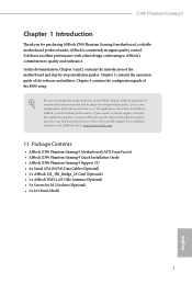
... support list on ASRock's website without notice. ASRock website http://www.asrock.com. 1.1 Package Contents • ASRock Z390 Phantom Gaming 9 Motherboard (ATX Form Factor) • ASRock Z390 Phantom Gaming 9 Quick Installation Guide • ASRock Z390 Phantom Gaming 9 Support CD • 4 x Serial ATA (SATA) Data Cables (Optional) • 1 x ASRock SLI_HB_Bridge_2S Card (Optional) • 1 x ASRock WiFi 2.4/5 GHz Antenna (Optional) • 3 x Screws for purchasing ASRock Z390 Phantom Gaming 9 motherboard, a reliable motherboard produced under ASRock's consistently stringent quality...
... support list on ASRock's website without notice. ASRock website http://www.asrock.com. 1.1 Package Contents • ASRock Z390 Phantom Gaming 9 Motherboard (ATX Form Factor) • ASRock Z390 Phantom Gaming 9 Quick Installation Guide • ASRock Z390 Phantom Gaming 9 Support CD • 4 x Serial ATA (SATA) Data Cables (Optional) • 1 x ASRock SLI_HB_Bridge_2S Card (Optional) • 1 x ASRock WiFi 2.4/5 GHz Antenna (Optional) • 3 x Screws for purchasing ASRock Z390 Phantom Gaming 9 motherboard, a reliable motherboard produced under ASRock's consistently stringent quality...

User Manual
Page 15
1.3 Motherboard Layout CLRBTN1 M2_WIFI1 ATX12V2 ATX12V1 CPU_FAN1 CPU_FAN2/WP CHA_FAN5/WP PS2 Keyboard /Mouse USB 3.1 Gen1 T: USB3_1 B: USB3_2 ATXPWR1 DDR4_B2 (64 bit, 288-pin... T: USB31_TA_3 LAN2 B: USB31_TC_1 (Intel I219V) Central/Bass LINE IN Top: Top: CHA_FAN1/WP CHA_FAN4/WP PCIE1 PCIE2 Z390 Phantom Gaming 9 PCIE3 CMOS Battery PCIE4 M2_2 M2_1 Ultra M.2 PCIe Gen3 x4 CHA_FAN6/WP 1 1 USB31_TC_2 USB3_5_6 SATA3_0_1 SATA3_2_3 Intel Z390 SATA3_4_5 USB3_7_8 SATA3_A1_A2 M2_3 PCIE5 HD_AUDIO1 ADDR_LED1 RGB_LED1 1 1 1 RGB_LED2 1 1 CHA_FAN2/WP TB1 TPMS1 1 1 USB3 ...
1.3 Motherboard Layout CLRBTN1 M2_WIFI1 ATX12V2 ATX12V1 CPU_FAN1 CPU_FAN2/WP CHA_FAN5/WP PS2 Keyboard /Mouse USB 3.1 Gen1 T: USB3_1 B: USB3_2 ATXPWR1 DDR4_B2 (64 bit, 288-pin... T: USB31_TA_3 LAN2 B: USB31_TC_1 (Intel I219V) Central/Bass LINE IN Top: Top: CHA_FAN1/WP CHA_FAN4/WP PCIE1 PCIE2 Z390 Phantom Gaming 9 PCIE3 CMOS Battery PCIE4 M2_2 M2_1 Ultra M.2 PCIe Gen3 x4 CHA_FAN6/WP 1 1 USB31_TC_2 USB3_5_6 SATA3_0_1 SATA3_2_3 Intel Z390 SATA3_4_5 USB3_7_8 SATA3_A1_A2 M2_3 PCIE5 HD_AUDIO1 ADDR_LED1 RGB_LED1 1 1 1 RGB_LED2 1 1 CHA_FAN2/WP TB1 TPMS1 1 1 USB3 ...

User Manual
Page 19
... Antenna 12 English 1.5 WiFi-802.11ac Module and ASRock WiFi 2.4/5 GHz Antenna WiFi-802.11ac + BT Module This motherboard comes with an exclusive WiFi 802.11 a/b/g/n/ac + BT v5.0 module (pre-installed on the rear I/O panel) that adds a whole new class of functionality into ...
... Antenna 12 English 1.5 WiFi-802.11ac Module and ASRock WiFi 2.4/5 GHz Antenna WiFi-802.11ac + BT Module This motherboard comes with an exclusive WiFi 802.11 a/b/g/n/ac + BT v5.0 module (pre-installed on the rear I/O panel) that adds a whole new class of functionality into ...

User Manual
Page 20
... or touch a safety grounded object before installing or removing the motherboard components. Z390 Phantom Gaming 9 Chapter 2 Installation This is an ATX form factor motherboard. Doing so may cause physical injuries and damages to motherboard components. • In order to avoid damage from static electricity to the motherboard's components, NEVER place your chassis to unplug the power cord...
... or touch a safety grounded object before installing or removing the motherboard components. Z390 Phantom Gaming 9 Chapter 2 Installation This is an ATX form factor motherboard. Doing so may cause physical injuries and damages to motherboard components. • In order to avoid damage from static electricity to the motherboard's components, NEVER place your chassis to unplug the power cord...

User Manual
Page 23
The cover must be placed if you wish to return the motherboard for after service. 16 English Please save and replace the cover if the processor is removed.
The cover must be placed if you wish to return the motherboard for after service. 16 English Please save and replace the cover if the processor is removed.

User Manual
Page 25
...incorrect orientation. It is unable to install identical (the same brand, speed, size and chip-type) DDR4 DIMM pairs. 2. otherwise, this motherboard and DIMM may be damaged. English 18 For dual channel configuration, you force the DIMM into a DDR4 slot; It will cause permanent ...damage to the motherboard and the DIMM if you always need to activate Dual Channel Memory Technology with only one correct orientation. 2.3 Installing Memory Modules (DIMM) This motherboard provides four 288-pin DDR4 (Double Data Rate 4) DIMM slots,...
...incorrect orientation. It is unable to install identical (the same brand, speed, size and chip-type) DDR4 DIMM pairs. 2. otherwise, this motherboard and DIMM may be damaged. English 18 For dual channel configuration, you force the DIMM into a DDR4 slot; It will cause permanent ...damage to the motherboard and the DIMM if you always need to activate Dual Channel Memory Technology with only one correct orientation. 2.3 Installing Memory Modules (DIMM) This motherboard provides four 288-pin DDR4 (Double Data Rate 4) DIMM slots,...

User Manual
Page 27
... or SLITM x8 Mode x8 N/A Three Graphics Cards in 3-Way CrossFireXTM Mode x8 x4 x4 For a better thermal environment, please connect a chassis fan to the motherboard's chassis fan connector (CHA_FAN1~6/WP) when using multiple graphics cards. PCIe slots: PCIE1 (PCIe 3.0 x1 slot) is unplugged. Please read the documentation of the expansion... the power cord is used for PCI Express x4 lane width graphics cards. 2.4 Expansion Slots (PCI Express Slots) There are 5 PCI Express slots on the motherboard.
... or SLITM x8 Mode x8 N/A Three Graphics Cards in 3-Way CrossFireXTM Mode x8 x4 x4 For a better thermal environment, please connect a chassis fan to the motherboard's chassis fan connector (CHA_FAN1~6/WP) when using multiple graphics cards. PCIe slots: PCIE1 (PCIe 3.0 x1 slot) is unplugged. Please read the documentation of the expansion... the power cord is used for PCI Express x4 lane width graphics cards. 2.4 Expansion Slots (PCI Express Slots) There are 5 PCI Express slots on the motherboard.

User Manual
Page 29
... LED is off when the system is in S4 sleep state or powered off your chassis front panel module to this header according to the motherboard. The front panel design may configure the way to turn off (S5). A front panel module mainly consists of power button, reset button, power LED, hard...
... LED is off when the system is in S4 sleep state or powered off your chassis front panel module to this header according to the motherboard. The front panel design may configure the way to turn off (S5). A front panel module mainly consists of power button, reset button, power LED, hard...

User Manual
Page 31
... J_SENSE OUT2_R MIC2_R MIC2_L This header is one Front Panel Type C USB 3.1 Gen2 Header on this motherboard. Vbus IntA_PA_D+ IntA_PA_DGND IntA_PA_SSTX+ IntA_PA_SSTXGND IntA_PA_SSRX+ IntA_PA_SSRXVbus Vbus IntA_PA_SSRXIntA_PA_SSRX+ GND IntA_PA_SSTXIntA_PA_SSTX+ GND IntA_PA_DIntA_PA_D+ Vbus IntA_PB_SSRXIntA_PB_SSRX...+ GND IntA_PB_SSTXIntA_PB_SSTX+ GND IntA_PB_DIntA_PB_D+ Dummy 1 There are two USB 2.0 headers on this motherboard. GND IntA_PB_SSTX+ IntA_PB_SSTX- Front Panel Type C USB 3.1 Gen2 Header (26-pin USB31_TC_2) (see p.8, No....
... J_SENSE OUT2_R MIC2_R MIC2_L This header is one Front Panel Type C USB 3.1 Gen2 Header on this motherboard. Vbus IntA_PA_D+ IntA_PA_DGND IntA_PA_SSTX+ IntA_PA_SSTXGND IntA_PA_SSRX+ IntA_PA_SSRXVbus Vbus IntA_PA_SSRXIntA_PA_SSRX+ GND IntA_PA_SSTXIntA_PA_SSTX+ GND IntA_PA_DIntA_PA_D+ Vbus IntA_PB_SSRXIntA_PB_SSRX...+ GND IntA_PB_SSTXIntA_PB_SSTX+ GND IntA_PB_DIntA_PB_D+ Dummy 1 There are two USB 2.0 headers on this motherboard. GND IntA_PB_SSTX+ IntA_PB_SSTX- Front Panel Type C USB 3.1 Gen2 Header (26-pin USB31_TC_2) (see p.8, No....

User Manual
Page 32
...4 (4-pin CHA_FAN6/WP) CHA_FAN_SPEED 3 (see p.8, No. 11) FAN_VOLTAGE 2 GND 1 CPU Fan Connector (4-pin CPU_FAN1) (see p.8, No. 3) FAN_SPEED This motherboard pro- If you plan to (4-pin CHA_FAN2/WP) connect a 3-Pin chassis FAN_SPEED (see p.8, No. 34) connectors. If you use an AC'97 audio ... in the Realtek Control panel and adjust "Recording Volume". FAN_VOLTAGE_CONTROL GND FAN_SPEED_CONTROL vides a 4-Pin CPU fan (Quiet Fan) connector. Z390 Phantom Gaming 9 1. B. Connect Audio_R (RIN) to OUT2_R and Audio_L (LIN) to the "FrontMic" Tab in our manual and chassis ...
...4 (4-pin CHA_FAN6/WP) CHA_FAN_SPEED 3 (see p.8, No. 11) FAN_VOLTAGE 2 GND 1 CPU Fan Connector (4-pin CPU_FAN1) (see p.8, No. 3) FAN_SPEED This motherboard pro- If you plan to (4-pin CHA_FAN2/WP) connect a 3-Pin chassis FAN_SPEED (see p.8, No. 34) connectors. If you use an AC'97 audio ... in the Realtek Control panel and adjust "Recording Volume". FAN_VOLTAGE_CONTROL GND FAN_SPEED_CONTROL vides a 4-Pin CPU fan (Quiet Fan) connector. Z390 Phantom Gaming 9 1. B. Connect Audio_R (RIN) to OUT2_R and Audio_L (LIN) to the "FrontMic" Tab in our manual and chassis ...

User Manual
Page 33
...network security, protects digital identities, and ensures platform integrity. ATX Power Connector (24-pin ATXPWR1) (see p.8, No. 2) 8 5 This motherboard provides an 8-pin ATX 4 1 12V power connector. To use a 20-pin ATX power supply, please plug it along Pin 1 and ... plug fits into this connector in only one orientation. TPM Header (17-pin TPMS1) (see p.8, No. 4) FAN_SPEED_CONTROL CHA_FAN_SPEED FAN_VOLTAGE GND 4 This motherboard 3 2 provides a 4-Pin water 1 cooling CPU fan connector. GN D English 26 CPU/Water Pump Fan Connector (4-pin CPU_FAN2/WP) (see ...
...network security, protects digital identities, and ensures platform integrity. ATX Power Connector (24-pin ATXPWR1) (see p.8, No. 2) 8 5 This motherboard provides an 8-pin ATX 4 1 12V power connector. To use a 20-pin ATX power supply, please plug it along Pin 1 and ... plug fits into this connector in only one orientation. TPM Header (17-pin TPMS1) (see p.8, No. 4) FAN_SPEED_CONTROL CHA_FAN_SPEED FAN_VOLTAGE GND 4 This motherboard 3 2 provides a 4-Pin water 1 cooling CPU fan connector. GN D English 26 CPU/Water Pump Fan Connector (4-pin CPU_FAN2/WP) (see ...

User Manual
Page 35
English 28 Clear CMOS Button (CLRBTN1) (see p.10, No. 19) Clear CMOS Button allows users to quickly reset the system. This function is workable only when you power off the system. 2.7 Smart Switches The motherboard has three smart switches: Power Button, Reset Button and Clear CMOS Button. Reset Button (RSTBTN1) (see p.8, No. 18) Power Power Button allows users to quickly turn on/off your computer and unplug the power supply. Power Button (PWRBTN1) (see p.8, No. 17) Reset Reset Button allows users to quickly clear the CMOS values.
English 28 Clear CMOS Button (CLRBTN1) (see p.10, No. 19) Clear CMOS Button allows users to quickly reset the system. This function is workable only when you power off the system. 2.7 Smart Switches The motherboard has three smart switches: Power Button, Reset Button and Clear CMOS Button. Reset Button (RSTBTN1) (see p.8, No. 18) Power Power Button allows users to quickly turn on/off your computer and unplug the power supply. Power Button (PWRBTN1) (see p.8, No. 17) Reset Reset Button allows users to quickly clear the CMOS values.

User Manual
Page 38
... Cards Step 1 Insert one graphics card into PCIE2 slot and the other graphics card to the PCI Express graphics cards. 31 English Z390 Phantom Gaming 9 2.9 SLITM and Quad SLITM Operation Guide This motherboard supports NVIDIA® SLITM and Quad SLITM (Scalable Link Interface) technology that allows you to install up to use identical SLITM...
... Cards Step 1 Insert one graphics card into PCIE2 slot and the other graphics card to the PCI Express graphics cards. 31 English Z390 Phantom Gaming 9 2.9 SLITM and Quad SLITM Operation Guide This motherboard supports NVIDIA® SLITM and Quad SLITM (Scalable Link Interface) technology that allows you to install up to use identical SLITM...

User Manual
Page 41
...at least the minimum power your graphics card driver supports AMD CrossFireXTM technology. If you pair a 12-pipe CrossFireXTM Edition card with this motherboard. Different CrossFireXTM cards may require different methods to use identical CrossFireXTM-ready graphics cards that the cards are AMD certified. 2. Make sure... Download the drivers from the AMD's website: www.amd.com 3. 2.10 CrossFireXTM , 3-Way CrossFireXTM and Quad CrossFireXTM Operation Guide This motherboard supports CrossFireXTM, 3-way CrossFireXTM and Quad CrossFireXTM that allows you to install up to PCIE4 slot.
...at least the minimum power your graphics card driver supports AMD CrossFireXTM technology. If you pair a 12-pipe CrossFireXTM Edition card with this motherboard. Different CrossFireXTM cards may require different methods to use identical CrossFireXTM-ready graphics cards that the cards are AMD certified. 2. Make sure... Download the drivers from the AMD's website: www.amd.com 3. 2.10 CrossFireXTM , 3-Way CrossFireXTM and Quad CrossFireXTM Operation Guide This motherboard supports CrossFireXTM, 3-way CrossFireXTM and Quad CrossFireXTM that allows you to install up to PCIE4 slot.


