
User Manual
Page 4
... Power (EIRP) 18.5 + / -1.5 dbm 21.5 + / -1.5 dbm 18.5 + / -1.5 dbm (no TPC) 21.5 + / -1.5 dbm (TPC) 25.5 + / -1.5 dbm (no TPC) 28.5 + / -1.5 dbm (TPC) 8.5 + / -1.5 dbm This equipment should be installed and operated with minimum distance 20cm between the radiator & your body. Operations in the 5.15-5.35GHz band are restricted to indoor usage only.
... Power (EIRP) 18.5 + / -1.5 dbm 21.5 + / -1.5 dbm 18.5 + / -1.5 dbm (no TPC) 21.5 + / -1.5 dbm (TPC) 25.5 + / -1.5 dbm (no TPC) 28.5 + / -1.5 dbm (TPC) 8.5 + / -1.5 dbm This equipment should be installed and operated with minimum distance 20cm between the radiator & your body. Operations in the 5.15-5.35GHz band are restricted to indoor usage only.
User Manual
Page 5
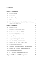
Contents Chapter 1 Introduction 1 1.1 Package Contents 1 1.2 Specifications 2 1.3 Motherboard Layout 7 1.4 I/O Panel 10 1.5 WiFi-802.11ac Module and ASRock WiFi 2.4/5 GHz Antennas (for Z370 Killer SLI/ac only) 13 Chapter 2 Installation 15 2.1 Installing the CPU 16 2.2 Installing the CPU Fan and Heatsink 19 2.3 Installing Memory Modules (DIMM) 20 2.4 Expansion Slots (PCI Express Slots) 22 2.5 Jumpers Setup 23 2.6 Onboard Headers and Connectors 24 2.7 SLITM...
Contents Chapter 1 Introduction 1 1.1 Package Contents 1 1.2 Specifications 2 1.3 Motherboard Layout 7 1.4 I/O Panel 10 1.5 WiFi-802.11ac Module and ASRock WiFi 2.4/5 GHz Antennas (for Z370 Killer SLI/ac only) 13 Chapter 2 Installation 15 2.1 Installing the CPU 16 2.2 Installing the CPU Fan and Heatsink 19 2.3 Installing Memory Modules (DIMM) 20 2.4 Expansion Slots (PCI Express Slots) 22 2.5 Jumpers Setup 23 2.6 Onboard Headers and Connectors 24 2.7 SLITM...

User Manual
Page 6
... 3.2 A-Tuning 40 3.2.1 Installing A-Tuning 40 3.2.2 Using A-Tuning 40 3.3 ASRock Live Update & APP Shop 43 3.3.1 UI Overview 43 3.3.2 Apps 44 3.3.3 BIOS & Drivers 47 3.3.4 Setting 48 3.4 ASRock RGB LED 49 Chapter 4 UEFI SETUP UTILITY 51 4.1 Introduction 51 4.2 EZ Mode 52 4.3 Advanced Mode 53 4.3.1 UEFI Menu Bar 53 4.3.2 Navigation Keys 54 4.4 Main Screen ...
... 3.2 A-Tuning 40 3.2.1 Installing A-Tuning 40 3.2.2 Using A-Tuning 40 3.3 ASRock Live Update & APP Shop 43 3.3.1 UI Overview 43 3.3.2 Apps 44 3.3.3 BIOS & Drivers 47 3.3.4 Setting 48 3.4 ASRock RGB LED 49 Chapter 4 UEFI SETUP UTILITY 51 4.1 Introduction 51 4.2 EZ Mode 52 4.3 Advanced Mode 53 4.3.1 UEFI Menu Bar 53 4.3.2 Navigation Keys 54 4.4 Main Screen ...
User Manual
Page 8
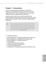
... notice. ASRock website http://www.asrock.com. 1.1 Package Contents • ASRock Z370 Killer SLI/ac / Z370 Killer SLI Motherboard (ATX Form Factor) • ASRock Z370 Killer SLI/ac / Z370 Killer SLI Quick Installation Guide • ASRock Z370 Killer SLI/ac / Z370 Killer SLI Support CD • 1 x I/O Panel Shield • 2 x Serial ATA (SATA) Data Cables (Optional) • 1 x ASRock SLI_HB_Bridge_2S Card (Optional) • 2 x Screws for M.2 Sockets (Optional) • 2 x ASRock WiFi 2.4/5 GHz Antennas (Optional) (for purchasing ASRock Z370 Killer SLI/ac / Z370 Killer SLI motherboard...
... notice. ASRock website http://www.asrock.com. 1.1 Package Contents • ASRock Z370 Killer SLI/ac / Z370 Killer SLI Motherboard (ATX Form Factor) • ASRock Z370 Killer SLI/ac / Z370 Killer SLI Quick Installation Guide • ASRock Z370 Killer SLI/ac / Z370 Killer SLI Support CD • 1 x I/O Panel Shield • 2 x Serial ATA (SATA) Data Cables (Optional) • 1 x ASRock SLI_HB_Bridge_2S Card (Optional) • 2 x Screws for M.2 Sockets (Optional) • 2 x ASRock WiFi 2.4/5 GHz Antennas (Optional) (for purchasing ASRock Z370 Killer SLI/ac / Z370 Killer SLI motherboard...
User Manual
Page 20
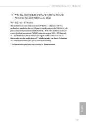
... ensures extraordinary low power consumption for WiFi 802.11 a/b/ g/n/ac connectivity standards and Bluetooth v4.2. Z370 Killer SLI/ac / Z370 Killer SLI 1.5 WiFi-802.11ac Module and ASRock WiFi 2.4/5 GHz Antennas (for Z370 Killer SLI/ac only) WiFi-802.11ac + BT Module This motherboard comes with an exclusive WiFi 802.11 a/b/g/n/ac + BT v4.2 module (pre-installed on the rear I/O panel) that adds a whole new...
... ensures extraordinary low power consumption for WiFi 802.11 a/b/ g/n/ac connectivity standards and Bluetooth v4.2. Z370 Killer SLI/ac / Z370 Killer SLI 1.5 WiFi-802.11ac Module and ASRock WiFi 2.4/5 GHz Antennas (for Z370 Killer SLI/ac only) WiFi-802.11ac + BT Module This motherboard comes with an exclusive WiFi 802.11 a/b/g/n/ac + BT v4.2 module (pre-installed on the rear I/O panel) that adds a whole new...

User Manual
Page 21
Turn the antenna clockwise until it is securely connected. Step 3 Set the WiFi 2.4/5 GHz Antenna as shown in the illustration. *You may need to the antenna connectors. WiFi Antennas Installation Guide Step 1 Prepare the WiFi 2.4/5 GHz Antennas that come with the package. Step 2 Connect the two WiFi 2.4/5 GHz Antennas to adjust the direction of the antenna for a stronger signal. 14 English
Turn the antenna clockwise until it is securely connected. Step 3 Set the WiFi 2.4/5 GHz Antenna as shown in the illustration. *You may need to the antenna connectors. WiFi Antennas Installation Guide Step 1 Prepare the WiFi 2.4/5 GHz Antennas that come with the package. Step 2 Connect the two WiFi 2.4/5 GHz Antennas to adjust the direction of the antenna for a stronger signal. 14 English

User Manual
Page 22
...'s components, NEVER place your chassis to do not touch the ICs. • Whenever you install the motherboard, study the configuration of the following precautions before you install motherboard components or change any components, place them on a carpet. Z370 Killer SLI/ac / Z370 Killer SLI Chapter 2 Installation This is an ATX form factor motherboard. Failure to ensure that comes with the...
...'s components, NEVER place your chassis to do not touch the ICs. • Whenever you install the motherboard, study the configuration of the following precautions before you install motherboard components or change any components, place them on a carpet. Z370 Killer SLI/ac / Z370 Killer SLI Chapter 2 Installation This is an ATX form factor motherboard. Failure to ensure that comes with the...

User Manual
Page 23
Do not force to insert the CPU into the socket, please check if the PnP cap is on the socket, if the CPU surface is found. Before you insert the 1151-Pin CPU into the socket if above situation is unclean, or if there are any bent pins in the socket. Otherwise, the CPU will be seriously damaged. 2. Unplug all power cables before installing the CPU. 1 A B 2 16 English 2.1 Installing the CPU 1.
Do not force to insert the CPU into the socket, please check if the PnP cap is on the socket, if the CPU surface is found. Before you insert the 1151-Pin CPU into the socket if above situation is unclean, or if there are any bent pins in the socket. Otherwise, the CPU will be seriously damaged. 2. Unplug all power cables before installing the CPU. 1 A B 2 16 English 2.1 Installing the CPU 1.

User Manual
Page 26
Z370 Killer SLI/ac / Z370 Killer SLI 2.2 Installing the CPU Fan and Heatsink 1 2 CPU_FAN English 19
Z370 Killer SLI/ac / Z370 Killer SLI 2.2 Installing the CPU Fan and Heatsink 1 2 CPU_FAN English 19

User Manual
Page 27
... Priority 1 2 DDR4_A1 Populated DDR4_A2 Populated Populated DDR4_B1 Populated DDR4_B2 Populated Populated The DIMM only fits in one or three memory module installed. 3. For dual channel configuration, you force the DIMM into a DDR4 slot; English 20 It is unable to activate Dual Channel...It will cause permanent damage to the motherboard and the DIMM if you always need to install a DDR, DDR2 or DDR3 memory module into the slot at incorrect orientation. 2.3 Installing Memory Modules (DIMM) This motherboard provides four 288-pin DDR4 (Double Data Rate 4) DIMM...
... Priority 1 2 DDR4_A1 Populated DDR4_A2 Populated Populated DDR4_B1 Populated DDR4_B2 Populated Populated The DIMM only fits in one or three memory module installed. 3. For dual channel configuration, you force the DIMM into a DDR4 slot; English 20 It is unable to activate Dual Channel...It will cause permanent damage to the motherboard and the DIMM if you always need to install a DDR, DDR2 or DDR3 memory module into the slot at incorrect orientation. 2.3 Installing Memory Modules (DIMM) This motherboard provides four 288-pin DDR4 (Double Data Rate 4) DIMM...

User Manual
Page 29
... Express x1 lane width cards. PCIE5 (PCIe 3.0 x1 slot) is used for PCI Express x1 lane width cards. PCIE6 (PCIe 3.0 x1 slot) is unplugged. Before installing an expansion card, please make necessary hardware settings for PCI Express x1 lane width cards. 2.4 Expansion Slots (PCI Express Slots) There are 6 PCI Express slots... expansion card and make sure that the power supply is switched off or the power cord is used for the card before you start the installation.
... Express x1 lane width cards. PCIE5 (PCIe 3.0 x1 slot) is used for PCI Express x1 lane width cards. PCIE6 (PCIe 3.0 x1 slot) is unplugged. Before installing an expansion card, please make necessary hardware settings for PCI Express x1 lane width cards. 2.4 Expansion Slots (PCI Express Slots) There are 6 PCI Express slots... expansion card and make sure that the power supply is switched off or the power cord is used for the card before you start the installation.

User Manual
Page 33
C. Connect Ground (GND) to MIC2_L. D. If you use an AC'97 audio panel, please install it to Pin 1-3. Connect Mic_IN (MIC) to Ground (GND). E. English 26 MIC_RET and OUT_RET are for connecting audio devices to the ground pin. Chassis Optional/... is for the HD audio panel only. If you plan to connect a 3-Pin chassis water cooler fan, please connect it to connect them for the AC'97 audio panel. To activate the front mic, go to OUT2_L. Connect Audio_R (RIN) to OUT2_R and Audio_L (LIN) to the "FrontMic" Tab in our...
C. Connect Ground (GND) to MIC2_L. D. If you use an AC'97 audio panel, please install it to Pin 1-3. Connect Mic_IN (MIC) to Ground (GND). E. English 26 MIC_RET and OUT_RET are for connecting audio devices to the ground pin. Chassis Optional/... is for the HD audio panel only. If you plan to connect a 3-Pin chassis water cooler fan, please connect it to connect them for the AC'97 audio panel. To activate the front mic, go to OUT2_L. Connect Audio_R (RIN) to OUT2_R and Audio_L (LIN) to the "FrontMic" Tab in our...
User Manual
Page 34
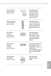
... a Thunderbolt™ add-in card (AIC) to the Thunderbolt AIC connector via the GPIO cable. * Please install the Thunderbolt™ AIC card to Pin 1-3. 12 24 1 13 This motherboard provides a 24-pin ATX power connector. Z370 Killer SLI/ac / Z370 Killer SLI CPU Fan Connector (4-pin CPU_FAN1) (see p.7 or 8, No. 4) ATX Power Connector (24-pin ATXPWR1) (see p.7 or...
... a Thunderbolt™ add-in card (AIC) to the Thunderbolt AIC connector via the GPIO cable. * Please install the Thunderbolt™ AIC card to Pin 1-3. 12 24 1 13 This motherboard provides a 24-pin ATX power connector. Z370 Killer SLI/ac / Z370 Killer SLI CPU Fan Connector (4-pin CPU_FAN1) (see p.7 or 8, No. 4) ATX Power Connector (24-pin ATXPWR1) (see p.7 or...

User Manual
Page 35
... positive and negative pins before connecting the cables. This connector supports Trusted Platform Module (TPM) system, which allows users to the pin assignments. Caution: Never install the RGB LED cable in the wrong orientation; English 28 Chassis Intrusion Header (2-pin CI1) (see p.7 or 8, No. 18) 1 GND Signal TPM Header (17-pin...
... positive and negative pins before connecting the cables. This connector supports Trusted Platform Module (TPM) system, which allows users to the pin assignments. Caution: Never install the RGB LED cable in the wrong orientation; English 28 Chassis Intrusion Header (2-pin CI1) (see p.7 or 8, No. 18) 1 GND Signal TPM Header (17-pin...
User Manual
Page 36
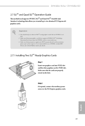
...your graphics card driver supports NVIDIA® SLITM technology. Z370 Killer SLI/ac / Z370 Killer SLI 2.7 SLITM and Quad SLITM Operation Guide This motherboard supports NVIDIA® SLITM and Quad SLITM (Scalable Link Interface) technology that allows you to install up to PCIE4 slot. Please refer to the NVIDIA&#...174; website for details. 2.7.1 Installing Two SLITM-Ready Graphics Cards Step 1 Insert one graphics card into PCIE2 slot and...
...your graphics card driver supports NVIDIA® SLITM technology. Z370 Killer SLI/ac / Z370 Killer SLI 2.7 SLITM and Quad SLITM Operation Guide This motherboard supports NVIDIA® SLITM and Quad SLITM (Scalable Link Interface) technology that allows you to install up to PCIE4 slot. Please refer to the NVIDIA&#...174; website for details. 2.7.1 Installing Two SLITM-Ready Graphics Cards Step 1 Insert one graphics card into PCIE2 slot and...
User Manual
Page 38
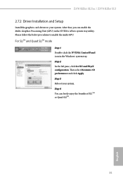
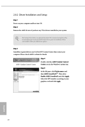
After that, you can freely enjoy the benefits of SLITM or Quad SLITM. 31 English Step 2 In the left pane, click Set SLI and PhysX configuration. Step 4 You can enable the Multi-Graphics Processing Unit (GPU) in the Windows® system tray. For SLITM and... Panel icon in the NVIDIA® nView system tray utility. Step 3 Reboot your system. Then select Maximize 3D performance and click Apply. Z370 Killer SLI/ac / Z370 Killer SLI 2.7.2 Driver Installation and Setup Install the graphics card drivers to enable the multi-GPU. Please follow the below procedures to your system.
After that, you can freely enjoy the benefits of SLITM or Quad SLITM. 31 English Step 2 In the left pane, click Set SLI and PhysX configuration. Step 4 You can enable the Multi-Graphics Processing Unit (GPU) in the Windows® system tray. For SLITM and... Panel icon in the NVIDIA® nView system tray utility. Step 3 Reboot your system. Then select Maximize 3D performance and click Apply. Z370 Killer SLI/ac / Z370 Killer SLI 2.7.2 Driver Installation and Setup Install the graphics card drivers to enable the multi-GPU. Please follow the below procedures to your system.
User Manual
Page 39
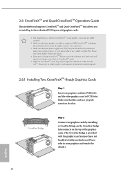
...card, both cards will operate as 12-pipe cards while in CrossFireXTM mode. 5. Please refer to the AMD's website for detailed installation guide. 2.8.1 Installing Two CrossFireXTM-Ready Graphics Cards Step 1 Insert one graphics card into PCIE2 slot and the other graphics card to AMD graphics card... manuals for details. 4. CrossFire Bridge Step 2 Connect two graphics cards by installing a CrossFire Bridge on the CrossFire Bridge Interconnects on the slots. Please refer to PCIE4 slot. Please refer to enable CrossFireXTM. 2.8 ...
...card, both cards will operate as 12-pipe cards while in CrossFireXTM mode. 5. Please refer to the AMD's website for detailed installation guide. 2.8.1 Installing Two CrossFireXTM-Ready Graphics Cards Step 1 Insert one graphics card into PCIE2 slot and the other graphics card to AMD graphics card... manuals for details. 4. CrossFire Bridge Step 2 Connect two graphics cards by installing a CrossFire Bridge on the CrossFire Bridge Interconnects on the slots. Please refer to PCIE4 slot. Please refer to enable CrossFireXTM. 2.8 ...
User Manual
Page 41
... Setup Step 1 Power on your graphics card and click Apply. We recommend using this utility to uninstall any VGA drivers installed in the Windows® system tray. AMD Catalyst Control Center Step 4 Double-click the AMD Catalyst Control Center icon in your computer. English ...34 Please check AMD's website for details. Then select Enable AMD CrossFireX and click Apply. The Catalyst Uninstaller is an optional download. Step 3 Install the required drivers and CATALYST Control Center then restart your system. Please check AMD's website for AMD driver updates.
... Setup Step 1 Power on your graphics card and click Apply. We recommend using this utility to uninstall any VGA drivers installed in the Windows® system tray. AMD Catalyst Control Center Step 4 Double-click the AMD Catalyst Control Center icon in your computer. English ...34 Please check AMD's website for details. Then select Enable AMD CrossFireX and click Apply. The Catalyst Uninstaller is an optional download. Step 3 Install the required drivers and CATALYST Control Center then restart your system. Please check AMD's website for AMD driver updates.

User Manual
Page 42
... module up to Gen3 x4 (32 Gb/s). * If M2_1 is occupied by a SATA-type M.2 device, SATA_5 will be disabled. Z370 Killer SLI/ac / Z370 Killer SLI 2.9 M.2_SSD (NGFF) Module Installation Guide The M.2, also known as the Next Generation Form Factor (NGFF), is occupied by a SATA-type M.2 device, SATA_0 will be... disabled. * If M2_2 is a small size and versatile card edge connector that aims to replace mPCIe and mSATA. Installing the M.2_SSD (NGFF) Module Step 1 Prepare a M.2_SSD (NGFF) module and the screw. 5 4 3 2 1 Step 2 Depending on the PCB ...
... module up to Gen3 x4 (32 Gb/s). * If M2_1 is occupied by a SATA-type M.2 device, SATA_5 will be disabled. Z370 Killer SLI/ac / Z370 Killer SLI 2.9 M.2_SSD (NGFF) Module Installation Guide The M.2, also known as the Next Generation Form Factor (NGFF), is occupied by a SATA-type M.2 device, SATA_0 will be... disabled. * If M2_2 is a small size and versatile card edge connector that aims to replace mPCIe and mSATA. Installing the M.2_SSD (NGFF) Module Step 1 Prepare a M.2_SSD (NGFF) module and the screw. 5 4 3 2 1 Step 2 Depending on the PCB ...
User Manual
Page 46
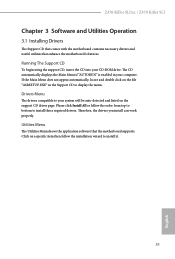
...into your system will be auto-detected and listed on the support CD driver page. Drivers Menu The drivers compatible to install those required drivers. Click on the file "ASRSETUP.EXE" in your computer. Utilities Menu The Utilities Menu shows the application... is enabled in the Support CD to install it. 39 English Therefore, the drivers you install can work properly. Please click Install All or follow the installation wizard to display the menu. Z370 Killer SLI/ac / Z370 Killer SLI Chapter 3 Software and Utilities Operation 3.1 Installing Drivers The Support CD that comes with the...
...into your system will be auto-detected and listed on the support CD driver page. Drivers Menu The drivers compatible to install those required drivers. Click on the file "ASRSETUP.EXE" in your computer. Utilities Menu The Utilities Menu shows the application... is enabled in the Support CD to install it. 39 English Therefore, the drivers you install can work properly. Please click Install All or follow the installation wizard to display the menu. Z370 Killer SLI/ac / Z370 Killer SLI Chapter 3 Software and Utilities Operation 3.1 Installing Drivers The Support CD that comes with the...


