

Intel Rapid Storage Guide
Page 12
... the following steps to save the BIOS settings and exit the BIOS Setup program. Enable RAID in System BIOS Use the instructions included with your motherboard to enable RAID in the system BIOS, a RAID volume must be created, and the F6 installation method must be used to load the Intel®...
... the following steps to save the BIOS settings and exit the BIOS Setup program. Enable RAID in System BIOS Use the instructions included with your motherboard to enable RAID in the system BIOS, a RAID volume must be created, and the F6 installation method must be used to load the Intel®...
RAID Installation Guide
Page 2
1. This section will guide you how to SATA Hard Disks Installation 1.1 Serial ATA (SATA) Hard Disks Installation Intel chipset supports Serial ATA (SATA) hard disks with RAID functions, including RAID 0, RAID 1, RAID 5, RAID 10 and Intel Rapid Storage. You may install SATA hard disks on SATA ports. 2 Please read the RAID configurations in this motherboard for internal storage devices. Guide to create RAID on this guide carefully according to the Intel southbridge chipset that your motherboard adopts.
1. This section will guide you how to SATA Hard Disks Installation 1.1 Serial ATA (SATA) Hard Disks Installation Intel chipset supports Serial ATA (SATA) hard disks with RAID functions, including RAID 0, RAID 1, RAID 5, RAID 10 and Intel Rapid Storage. You may install SATA hard disks on SATA ports. 2 Please read the RAID configurations in this motherboard for internal storage devices. Guide to create RAID on this guide carefully according to the Intel southbridge chipset that your motherboard adopts.
RAID Installation Guide
Page 3
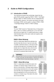
2. For optimal performance, please install identical drives of the RAID 0 Disk will double the data transfer rate of RAID This motherboard adopts Intel southbridge chipset that integrates RAID controller supporting RAID 0 / RAID 1/ Intel Rapid Storage / RAID 10 / RAID 5 function with four independent Serial ATA (SATA) channels. ...
2. For optimal performance, please install identical drives of the RAID 0 Disk will double the data transfer rate of RAID This motherboard adopts Intel southbridge chipset that integrates RAID controller supporting RAID 0 / RAID 1/ Intel Rapid Storage / RAID 10 / RAID 5 function with four independent Serial ATA (SATA) channels. ...
RAID Installation Guide
Page 18
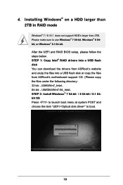
... boot. 18 STEP 1: Copy Intel® RAID drivers into a USB flash disk You can download the drivers from ASRock's website and unzip the files into a USB flash disk or copy the files from ASRock's motherboard support CD. (Please copy the files under the following directory: 32 bit: ..\i386\Win7_Intel.. 64-bit: ..\AMD64\Win7...
... boot. 18 STEP 1: Copy Intel® RAID drivers into a USB flash disk You can download the drivers from ASRock's website and unzip the files into a USB flash disk or copy the files from ASRock's motherboard support CD. (Please copy the files under the following directory: 32 bit: ..\i386\Win7_Intel.. 64-bit: ..\AMD64\Win7...
RAID Installation Guide
Page 20
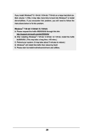
..., you install Windows® 8.1 64-bit / 8 64-bit / 7 64-bit on a large hard disk (ex. Reboot your system. (It may take more time to install motherboard drivers and utilities. 20 If you will install this hotfix then reboot by itself.
..., you install Windows® 8.1 64-bit / 8 64-bit / 7 64-bit on a large hard disk (ex. Reboot your system. (It may take more time to install motherboard drivers and utilities. 20 If you will install this hotfix then reboot by itself.

User Manual
Page 2
...are used only for a particular purpose. CALIFORNIA, USA ONLY The Lithium battery adopted on this motherboard contains Perchlorate, a toxic substance controlled in this documentation, ASRock does not provide warranty of any kind, either expressed or implied, including but not limited ... may or may appear in the documentation or product. "Perchlorate Material-special handling may cause undesired operation. ASRock assumes no event shall ASRock, its directors, officers, employees, or agents be registered trademarks or copyrights of merchantability or fitness for identification...
...are used only for a particular purpose. CALIFORNIA, USA ONLY The Lithium battery adopted on this motherboard contains Perchlorate, a toxic substance controlled in this documentation, ASRock does not provide warranty of any kind, either expressed or implied, including but not limited ... may or may appear in the documentation or product. "Perchlorate Material-special handling may cause undesired operation. ASRock assumes no event shall ASRock, its directors, officers, employees, or agents be registered trademarks or copyrights of merchantability or fitness for identification...

User Manual
Page 4
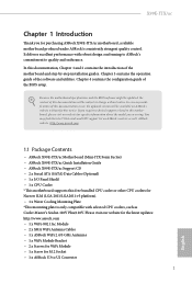
Contents Chapter 1 Introduction 1 1.1 Package Contents 1 1.2 Specifications 2 1.3 Motherboard Layout 6 1.4 I/O Panel 8 1.5 WiFi-802.11ac Module and ASRock WiFi 2.4/5 GHz Antenna 10 Chapter 2 Installation 14 2.1 Installing the CPU 15 2.2 Installing the CPU Fan and Heatsink 18 2.3 Installing Memory Modules (DIMM) 20 2.4 ...Headers and Connectors 24 2.7 Smart Switches 28 2.8 M.2_SSD (NGFF) Module Installation Guide 29 Chapter 3 Software and Utilities Operation 32 3.1 Installing Drivers 32 3.2 A-Tuning 33 3.3 ASRock APP Shop 39 3.3.1 UI Overview 39 3.3.2 Apps 40
Contents Chapter 1 Introduction 1 1.1 Package Contents 1 1.2 Specifications 2 1.3 Motherboard Layout 6 1.4 I/O Panel 8 1.5 WiFi-802.11ac Module and ASRock WiFi 2.4/5 GHz Antenna 10 Chapter 2 Installation 14 2.1 Installing the CPU 15 2.2 Installing the CPU Fan and Heatsink 18 2.3 Installing Memory Modules (DIMM) 20 2.4 ...Headers and Connectors 24 2.7 Smart Switches 28 2.8 M.2_SSD (NGFF) Module Installation Guide 29 Chapter 3 Software and Utilities Operation 32 3.1 Installing Drivers 32 3.2 A-Tuning 33 3.3 ASRock APP Shop 39 3.3.1 UI Overview 39 3.3.2 Apps 40
User Manual
Page 6
...; 1 x Water Cooling Mounting Plate *This mounting plate is only compatible with robust design conforming to ASRock's commitment to quality and endurance. ASRock website http://www.asrock.com. 1.1 Package Contents • ASRock X99E-ITX/ac Motherboard (Mini-ITX Form Factor) • ASRock X99E-ITX/ac Quick Installation Guide • ASRock X99E-ITX/ac Support CD • 2 x Serial ATA (SATA) Data Cables (Optional) • 1 x I/O Panel Shield • 1 x CPU Cooler...
...; 1 x Water Cooling Mounting Plate *This mounting plate is only compatible with robust design conforming to ASRock's commitment to quality and endurance. ASRock website http://www.asrock.com. 1.1 Package Contents • ASRock X99E-ITX/ac Motherboard (Mini-ITX Form Factor) • ASRock X99E-ITX/ac Quick Installation Guide • ASRock X99E-ITX/ac Support CD • 2 x Serial ATA (SATA) Data Cables (Optional) • 1 x I/O Panel Shield • 1 x CPU Cooler...
User Manual
Page 11
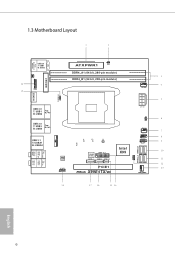
1.3 Motherboard Layout 1 2 MPCIE1 CLRMOS1 1 PS2 Keyboard /Mouse USB 2.0 T: USB1 B: USB2 1 20 TPMS1 19 CLRCBTN1 CMOS Battery 1 AT X P W R 1 CI1 DDR4_A1 (64 bit, 288-pin module) DDR4_B1 (64 ... PLED1 1 6 Ct1 CT2 Ct3 CPU_FAN1 7 USB3_4 8 1 PLED PWRBTN 1 9 HDLED RESET PANEL1 Intel 10 USB3_5_6 X99 128Mb BIOS SATA3_4 SATA3_5 SATAE_4_5 11 SPEAKER1 1 SATA3_2_3 SATA3_0_1 PCIE1 X99E-ITX/ac 12 13 CHA_FAN1 Bottom: Optical SPDIF 18 17 16 15 14 English 6
1.3 Motherboard Layout 1 2 MPCIE1 CLRMOS1 1 PS2 Keyboard /Mouse USB 2.0 T: USB1 B: USB2 1 20 TPMS1 19 CLRCBTN1 CMOS Battery 1 AT X P W R 1 CI1 DDR4_A1 (64 bit, 288-pin module) DDR4_B1 (64 ... PLED1 1 6 Ct1 CT2 Ct3 CPU_FAN1 7 USB3_4 8 1 PLED PWRBTN 1 9 HDLED RESET PANEL1 Intel 10 USB3_5_6 X99 128Mb BIOS SATA3_4 SATA3_5 SATAE_4_5 11 SPEAKER1 1 SATA3_2_3 SATA3_0_1 PCIE1 X99E-ITX/ac 12 13 CHA_FAN1 Bottom: Optical SPDIF 18 17 16 15 14 English 6
User Manual
Page 15
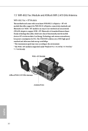
... Energy Technology and ensures extraordinary low power consumption for WiFi 802.11 a/b/g/n/ac connectivity standards and Bluetooth v4.0. 1.5 WiFi-802.11ac Module and ASRock WiFi 2.4/5 GHz Antenna WiFi-802.11ac + BT Module This motherboard comes with an exclusive WiFi 802.11 a/b/g/n/ac + BT v4.0 module that adds a whole new class of functionality into the...
... Energy Technology and ensures extraordinary low power consumption for WiFi 802.11 a/b/g/n/ac connectivity standards and Bluetooth v4.0. 1.5 WiFi-802.11ac Module and ASRock WiFi 2.4/5 GHz Antenna WiFi-802.11ac + BT Module This motherboard comes with an exclusive WiFi 802.11 a/b/g/n/ac + BT v4.0 module that adds a whole new class of functionality into the...

User Manual
Page 19
...motherboard components. Doing so may cause physical injuries and damages to motherboard components. • In order to avoid damage from static electricity to ensure that the motherboard... fits into it. Pre-installation Precautions Take note of the following precautions before you install motherboard .... • When placing screws to secure the motherboard to unplug the power cord before you handle the...motherboard, study the configuration of your chassis to the motherboard's components, NEVER place your motherboard directly on a carpet. Before you uninstall any motherboard...
...motherboard components. Doing so may cause physical injuries and damages to motherboard components. • In order to avoid damage from static electricity to ensure that the motherboard... fits into it. Pre-installation Precautions Take note of the following precautions before you install motherboard .... • When placing screws to secure the motherboard to unplug the power cord before you handle the...motherboard, study the configuration of your chassis to the motherboard's components, NEVER place your motherboard directly on a carpet. Before you uninstall any motherboard...
User Manual
Page 22
6 7 A B 8 X99E-ITX/ac A B English The cover must be placed if returning the motherboard for after service. 17
6 7 A B 8 X99E-ITX/ac A B English The cover must be placed if returning the motherboard for after service. 17

User Manual
Page 23
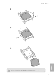
This motherboard supports this free bundled CPU cooler or other CPU coolers for Narrow ILM (LGA 2011/LGA2011-v3 platform). 1 DYNATRON NATRON English 2 18 DYNATRON DY Installing the CPU fan upside down may cause damage. Before you installed the heatsink, you need to spray thermal interface material between the CPU and the heatsink to improve heat dissipation. 2. 2.2 Installing the CPU Fan and Heatsink 1.
This motherboard supports this free bundled CPU cooler or other CPU coolers for Narrow ILM (LGA 2011/LGA2011-v3 platform). 1 DYNATRON NATRON English 2 18 DYNATRON DY Installing the CPU fan upside down may cause damage. Before you installed the heatsink, you need to spray thermal interface material between the CPU and the heatsink to improve heat dissipation. 2. 2.2 Installing the CPU Fan and Heatsink 1.

User Manual
Page 25
2.3 Installing Memory Modules (DIMM) This motherboard provides two 288-pin DDR4 (Double Data Rate 4) DIMM slots, and supports Dual Channel Memory Technology. 1. It is unable to install identical (the same brand, ... module into the slot at incorrect orientation. 20 English The DIMM only fits in one memory module installed. 3. It will cause permanent damage to the motherboard and the DIMM if you always need to activate Dual Channel Memory Technology with only one correct orientation. For dual channel configuration, you force the...
2.3 Installing Memory Modules (DIMM) This motherboard provides two 288-pin DDR4 (Double Data Rate 4) DIMM slots, and supports Dual Channel Memory Technology. 1. It is unable to install identical (the same brand, ... module into the slot at incorrect orientation. 20 English The DIMM only fits in one memory module installed. 3. It will cause permanent damage to the motherboard and the DIMM if you always need to activate Dual Channel Memory Technology with only one correct orientation. For dual channel configuration, you force the...

User Manual
Page 27
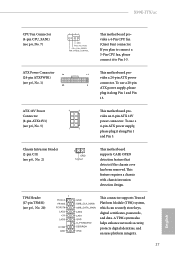
PCIe slot: PCIE1 (PCIe 3.0 x16 slot) is unplugged. Please read the documentation of the expansion card and make sure that the power supply is switched off or the power cord is used for WiFi module. 22 English mini-PCIe slot: MPCIE1 (mini-PCIe slot) is 1 PCI Express slot and 1 mini-PCI Express slot on the motherboard. 2.4 Expansion Slots (PCI Express Slots) There is used for the card before you start the installation. Before installing an expansion card, please make necessary hardware settings for PCI Express x16 lane width graphics cards.
PCIe slot: PCIE1 (PCIe 3.0 x16 slot) is unplugged. Please read the documentation of the expansion card and make sure that the power supply is switched off or the power cord is used for WiFi module. 22 English mini-PCIe slot: MPCIE1 (mini-PCIe slot) is 1 PCI Express slot and 1 mini-PCI Express slot on the motherboard. 2.4 Expansion Slots (PCI Express Slots) There is used for the card before you start the installation. Before installing an expansion card, please make necessary hardware settings for PCI Express x16 lane width graphics cards.

User Manual
Page 29
... Onboard headers and connectors are matched correctly. Placing jumper caps over these headers and connectors. The front panel design may configure the way to the motherboard. The LED is on the chassis front panel.
... Onboard headers and connectors are matched correctly. Placing jumper caps over these headers and connectors. The front panel design may configure the way to the motherboard. The LED is on the chassis front panel.
User Manual
Page 30
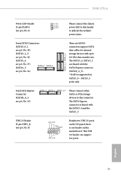
... connector is shared with the SATA Express connector (SATAE_4_5). * RAID is one header on SATA3_0 ~ SATA3_5 ports only. This USB 2.0 header can support two ports. X99E-ITX/ac Power LED Header (3-pin PLED1) (see p.6, No. 15) SATA3_4 SATA3_5 SATAE_4_5 Please connect either SATA or PCIe storage devices to this connector. The SATA3_4, SATA3_5... p.6, No. 17) (SATA3_5: SATA3_4 SATA3_5 see p.6, No. 8) USB_PWR PP+ GND DUMMY 1 GND P+ PUSB_PWR Besides two USB 2.0 ports on the I/O panel, there is supported on this motherboard.
... connector is shared with the SATA Express connector (SATAE_4_5). * RAID is one header on SATA3_0 ~ SATA3_5 ports only. This USB 2.0 header can support two ports. X99E-ITX/ac Power LED Header (3-pin PLED1) (see p.6, No. 15) SATA3_4 SATA3_5 SATAE_4_5 Please connect either SATA or PCIe storage devices to this connector. The SATA3_4, SATA3_5... p.6, No. 17) (SATA3_5: SATA3_4 SATA3_5 see p.6, No. 8) USB_PWR PP+ GND DUMMY 1 GND P+ PUSB_PWR Besides two USB 2.0 ports on the I/O panel, there is supported on this motherboard.
User Manual
Page 31
...fan connectors and match the black wire to the front panel audio header by the steps below: A. D. English If you use an AC'97 audio panel, please install it to the ground pin. E. IntA_P_SSRX+ GND IntA_P_SSTXIntA_P_SSTX+ GND IntA_P_DIntA_P_D+ Besides four USB 3.0 ports on... header is one header on the chassis must support HDA to function correctly. MIC_RET and OUT_RET are for the AC'97 audio panel. You don't need to this motherboard. Chassis Speaker Header (4-pin SPEAKER1) (see p.6, No. 14) ID IntA_P_D+ IntA_P_DGND IntA_P_SSTX+ IntA_P_SSTXGND IntA_P_SSRX+ ...
...fan connectors and match the black wire to the front panel audio header by the steps below: A. D. English If you use an AC'97 audio panel, please install it to the ground pin. E. IntA_P_SSRX+ GND IntA_P_SSTXIntA_P_SSTX+ GND IntA_P_DIntA_P_D+ Besides four USB 3.0 ports on... header is one header on the chassis must support HDA to function correctly. MIC_RET and OUT_RET are for the AC'97 audio panel. You don't need to this motherboard. Chassis Speaker Header (4-pin SPEAKER1) (see p.6, No. 14) ID IntA_P_D+ IntA_P_DGND IntA_P_SSTX+ IntA_P_SSTXGND IntA_P_SSRX+ ...
User Manual
Page 32
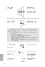
..., please plug it along Pin 1 and Pin 13. TPM Header (17-pin TPMS1) (see p.6, No. 7) 4 3 21 GND FAN_VOLTAGE CPU_FAN_SPEED FAN_SPEED_CONTROL This motherboard provides a 4-Pin CPU fan (Quiet Fan) connector. X99E-ITX/ac CPU Fan Connector (4-pin CPU_FAN1) (see p.6, No. 20) PCICLK FRAME PCIRST# This connector supports Trusted Platform Module (TPM) system, which can securely...
..., please plug it along Pin 1 and Pin 13. TPM Header (17-pin TPMS1) (see p.6, No. 7) 4 3 21 GND FAN_VOLTAGE CPU_FAN_SPEED FAN_SPEED_CONTROL This motherboard provides a 4-Pin CPU fan (Quiet Fan) connector. X99E-ITX/ac CPU Fan Connector (4-pin CPU_FAN1) (see p.6, No. 20) PCICLK FRAME PCIRST# This connector supports Trusted Platform Module (TPM) system, which can securely...

User Manual
Page 33
2.7 Smart Switches The motherboard has a Clear CMOS Switch, allowing users to quickly clear the CMOS values. Clear CMOS Switch (CLRCBTN) (see p.8, No. 14) Clear CMOS Switch allows users to clear the CMOS values. English 28 This function is workable only when you power off your computer and unplug the power supply.
2.7 Smart Switches The motherboard has a Clear CMOS Switch, allowing users to quickly clear the CMOS values. Clear CMOS Switch (CLRCBTN) (see p.8, No. 14) Clear CMOS Switch allows users to clear the CMOS values. English 28 This function is workable only when you power off your computer and unplug the power supply.


