
RAID Installation Guide
Page 1
AMD BIOS RAID Installation Guide ...2 1.1 Introduction to RAID...2 1.2 RAID Configurations Precautions 4 1.3 Legacy RAID ROM Configuration (for AMD X470, X370, B350, and A320 Chipsets 5 1.4 UEFI RAID Configuration (for AMD X399, X470, X370, B350, and A320 Chipsets 11 2. AMD Windows RAID Installation Guide 16 1 AMD RAID Installation Guide 1.
AMD BIOS RAID Installation Guide ...2 1.1 Introduction to RAID...2 1.2 RAID Configurations Precautions 4 1.3 Legacy RAID ROM Configuration (for AMD X470, X370, B350, and A320 Chipsets 5 1.4 UEFI RAID Configuration (for AMD X399, X470, X370, B350, and A320 Chipsets 11 2. AMD Windows RAID Installation Guide 16 1 AMD RAID Installation Guide 1.
RAID Installation Guide
Page 2
..."Redundant Array of the same model and capacity when creating a RAID set the option to RAID mode by using the onboard FastBuild BIOS utility under BIOS environment. It provides data protection and increases fault tolerance to the entire system since it will direct all applications to a second drive.... Hot-Plug any HDDs of the data in parallel, interleaved stacks. AMD BIOS RAID Installation Guide AMD BIOS RAID Installation Guide is called data striping that copies and maintains an identical image of a single disk alone while the two...
..."Redundant Array of the same model and capacity when creating a RAID set the option to RAID mode by using the onboard FastBuild BIOS utility under BIOS environment. It provides data protection and increases fault tolerance to the entire system since it will direct all applications to a second drive.... Hot-Plug any HDDs of the data in parallel, interleaved stacks. AMD BIOS RAID Installation Guide AMD BIOS RAID Installation Guide is called data striping that copies and maintains an identical image of a single disk alone while the two...

RAID Installation Guide
Page 5
... C. During system boot, press to exit. When the appropriate prompt appears during POST, press to . Set the "SATA Mode" option to enter the RAID BIOS setup utility. D. B. To create a new array, press on the "Create Array" option. *Be sure to create and configure the RAID disk. 1.3... Legacy RAID ROM Configuration (for AMD X470, X370, B350, and A320 Chipsets) Use legacy RAID ROM to delete the existing disk arrays before creating a new array. 5 B. During system boot, press...
... C. During system boot, press to exit. When the appropriate prompt appears during POST, press to . Set the "SATA Mode" option to enter the RAID BIOS setup utility. D. B. To create a new array, press on the "Create Array" option. *Be sure to create and configure the RAID disk. 1.3... Legacy RAID ROM Configuration (for AMD X470, X370, B350, and A320 Chipsets) Use legacy RAID ROM to delete the existing disk arrays before creating a new array. 5 B. During system boot, press...

RAID Installation Guide
Page 7
Select a caching mode and press to exit the RAID BIOS utility. 7 When completed, you will see the new array on the main screen. Press to proceed. Press to confirm and then press to return to the previous screen.
Select a caching mode and press to exit the RAID BIOS utility. 7 When completed, you will see the new array on the main screen. Press to proceed. Press to confirm and then press to return to the previous screen.

User Manual
Page 6
Chapter 3 Software and Utilities Operation 49 3.1 Installing Drivers 49 3.2 A-Tuning 50 3.2.1 Installing A-Tuning 50 3.2.2 Using A-Tuning 50 3.3 ASRock Live Update & APP Shop 53 3.3.1 UI Overview 53 3.3.2 Apps 54 3.3.3 BIOS & Drivers 57 3.3.4 Setting 58 3.4 ASRock Polychrome RGB 59 Chapter 4 UEFI SETUP UTILITY 62 4.1 Introduction 62 4.1.1 UEFI Menu Bar 62 4.1.2 Navigation Keys 63 4.2 Main Screen 64...
Chapter 3 Software and Utilities Operation 49 3.1 Installing Drivers 49 3.2 A-Tuning 50 3.2.1 Installing A-Tuning 50 3.2.2 Using A-Tuning 50 3.3 ASRock Live Update & APP Shop 53 3.3.1 UI Overview 53 3.3.2 Apps 54 3.3.3 BIOS & Drivers 57 3.3.4 Setting 58 3.4 ASRock Polychrome RGB 59 Chapter 4 UEFI SETUP UTILITY 62 4.1 Introduction 62 4.1.1 UEFI Menu Bar 62 4.1.2 Navigation Keys 63 4.2 Main Screen 64...
User Manual
Page 8
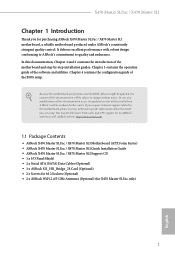
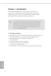
...) 1 English ASRock website http://www.asrock.com. 1.1 Package Contents • ASRock X470 Master SLI/ac / X470 Master SLI Motherboard (ATX Form Factor) • ASRock X470 Master SLI/ac / X470 Master SLI Quick Installation Guide • ASRock X470 Master SLI/ac / X470 Master SLI Support CD • 1 x I/O Panel Shield • 2 x Serial ATA (SATA) Data Cables (Optional) • 1 x ASRock SLI_HB_Bridge_2S Card (Optional) • 2 x Screws for M.2 Sockets (Optional) • 2 x ASRock WiFi 2.4/5 GHz Antennas (Optional) (for purchasing ASRock X470 Master SLI/ac / X470 Master SLI motherboard...
...) 1 English ASRock website http://www.asrock.com. 1.1 Package Contents • ASRock X470 Master SLI/ac / X470 Master SLI Motherboard (ATX Form Factor) • ASRock X470 Master SLI/ac / X470 Master SLI Quick Installation Guide • ASRock X470 Master SLI/ac / X470 Master SLI Support CD • 1 x I/O Panel Shield • 2 x Serial ATA (SATA) Data Cables (Optional) • 1 x ASRock SLI_HB_Bridge_2S Card (Optional) • 2 x Screws for M.2 Sockets (Optional) • 2 x ASRock WiFi 2.4/5 GHz Antennas (Optional) (for purchasing ASRock X470 Master SLI/ac / X470 Master SLI motherboard...
User Manual
Page 12
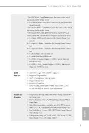
...4 USB 2.0 ports) (Supports ESD Protection) • 2 x USB 3.1 Gen1 Headers (Support 4 USB 3.1 Gen1 ports) (Supports ESD Protection) BIOS Feature • AMI UEFI Legal BIOS with GUI support • Supports "Plug and Play" • ACPI 5.1 compliance wake up events • Supports jumperfree • SMBIOS 2.3 support ...Fans • Voltage monitoring: +12V, +5V, +3.3V, CPU Vcore, VCORE_ NB, DRAM, PCH 1.05V, +1.8V, VDDP 5 English X470 Master SLI/ac / X470 Master SLI * The CPU/Water Pump Fan supports the water cooler fan of maximum 2A (24W) fan power. • 3 x Chassis/Water Pump Fan...
...4 USB 2.0 ports) (Supports ESD Protection) • 2 x USB 3.1 Gen1 Headers (Support 4 USB 3.1 Gen1 ports) (Supports ESD Protection) BIOS Feature • AMI UEFI Legal BIOS with GUI support • Supports "Plug and Play" • ACPI 5.1 compliance wake up events • Supports jumperfree • SMBIOS 2.3 support ...Fans • Voltage monitoring: +12V, +5V, +3.3V, CPU Vcore, VCORE_ NB, DRAM, PCH 1.05V, +1.8V, VDDP 5 English X470 Master SLI/ac / X470 Master SLI * The CPU/Water Pump Fan supports the water cooler fan of maximum 2A (24W) fan power. • 3 x Chassis/Water Pump Fan...

User Manual
Page 13
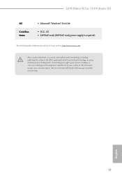
.../EuP ready power supply is required) * For detailed product information, please visit our website: http://www.asrock.com Please realize that there is a certain risk involved with overclocking, including adjusting the setting in the BIOS, applying Untied Overclocking Technology, or using third-party overclocking tools. We are not responsible for possible damage...
.../EuP ready power supply is required) * For detailed product information, please visit our website: http://www.asrock.com Please realize that there is a certain risk involved with overclocking, including adjusting the setting in the BIOS, applying Untied Overclocking Technology, or using third-party overclocking tools. We are not responsible for possible damage...

User Manual
Page 14
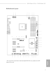
1.3 Motherboard Layout X470 Master SLI/ac / X470 Master SLI M2_WIFI_1* ATX12V1 ATX12V2 CPU_FAN2/WP CPU_FAN1 PS2 Keyboard/ Mouse HDMI1 ATXPWR1 DDR4_B2 (64 bit, 288-pin module) DDR4_B1 (64 bit, 288-pin ...: Center: REAR SPK Bottom: Optical SPDIF 1 RoHS USB3_9_10 Central/Bass LINE IN Top: Center: FRONT Bottom: MIC IN USB3_7_8 PCIE1 PCIE2 PCIE3 BIOS ROM M2_1 1 USB_5 1 AMD_FAN_LED1 1 AMD Promontory X470 SATA3_5_6 CHA_FAN1/WP SATA3_3_4 SATA3_1_2 PCIE4 PCIE5 PCIE6 HD_AUDIO1 COM1 1 1 1 TPMS1 Super I/O CMOS Battery SPK_PLED1 1 USB_3_4 USB_1_2 1 1 CHA_FAN3/WP ...
1.3 Motherboard Layout X470 Master SLI/ac / X470 Master SLI M2_WIFI_1* ATX12V1 ATX12V2 CPU_FAN2/WP CPU_FAN1 PS2 Keyboard/ Mouse HDMI1 ATXPWR1 DDR4_B2 (64 bit, 288-pin module) DDR4_B1 (64 bit, 288-pin ...: Center: REAR SPK Bottom: Optical SPDIF 1 RoHS USB3_9_10 Central/Bass LINE IN Top: Center: FRONT Bottom: MIC IN USB3_7_8 PCIE1 PCIE2 PCIE3 BIOS ROM M2_1 1 USB_5 1 AMD_FAN_LED1 1 AMD Promontory X470 SATA3_5_6 CHA_FAN1/WP SATA3_3_4 SATA3_1_2 PCIE4 PCIE5 PCIE6 HD_AUDIO1 COM1 1 1 1 TPMS1 Super I/O CMOS Battery SPK_PLED1 1 USB_3_4 USB_1_2 1 1 CHA_FAN3/WP ...

User Manual
Page 37
..." when a jumper cap is placed on these 2 pins. To clear and reset the system parameters to clear the CMOS when you just finish updating the BIOS, you must boot up the system first, and then shut it down before you need to default setup, please turn off the computer and unplug... the power cord from the power supply. After waiting for 5 seconds. Clear CMOS Jumper (CLRCMOS1) (see p.7, No. 18) 2-pin Jumper CLRCMOS1 allows you update the BIOS. Please remember toremove the jumper cap after you to short the pins on the pins, the jumper is "Open". English 30 If no jumper cap...
..." when a jumper cap is placed on these 2 pins. To clear and reset the system parameters to clear the CMOS when you just finish updating the BIOS, you must boot up the system first, and then shut it down before you need to default setup, please turn off the computer and unplug... the power cord from the power supply. After waiting for 5 seconds. Clear CMOS Jumper (CLRCMOS1) (see p.7, No. 18) 2-pin Jumper CLRCMOS1 allows you update the BIOS. Please remember toremove the jumper cap after you to short the pins on the pins, the jumper is "Open". English 30 If no jumper cap...

User Manual
Page 64
Click on Step 2 to see a list of recommended or critical updates for the BIOS or drivers. Step 3 Click Update to select one or more items you will see more details. X470 Master SLI/ac / X470 Master SLI 3.3.3 BIOS & Drivers Installing BIOS or Drivers When the "BIOS & Drivers" tab is selected, you want to update. Step 1 Please check the item information before update. Please update them all soon. Click to start the update process. 57 English
Click on Step 2 to see a list of recommended or critical updates for the BIOS or drivers. Step 3 Click Update to select one or more items you will see more details. X470 Master SLI/ac / X470 Master SLI 3.3.3 BIOS & Drivers Installing BIOS or Drivers When the "BIOS & Drivers" tab is selected, you want to update. Step 1 Please check the item information before update. Please update them all soon. Click to start the update process. 57 English

User Manual
Page 85
Note that it will always be used unless the interleaving is set to channel and the interleaving size is disabled, BIOS does not implement MemClear after memory training (only if non-ECC DIMMs are at the top of DRAM if some dies don't have memory regardless ...
Note that it will always be used unless the interleaving is set to channel and the interleaving size is disabled, BIOS does not implement MemClear after memory training (only if non-ECC DIMMs are at the top of DRAM if some dies don't have memory regardless ...
Quick Installation Guide
Page 5
Motherboard Layout X470 Master SLI/ac / X470 Master SLI M2_WIFI_1* ATX12V1 ATX12V2 CPU_FAN2/WP CPU_FAN1 PS2 Keyboard/ Mouse HDMI1 ATXPWR1 DDR4_B2 (64 bit, 288-pin module) DDR4_B1 (64 bit, 288-pin ...: Center: REAR SPK Bottom: Optical SPDIF 1 RoHS USB3_9_10 Central/Bass LINE IN Top: Center: FRONT Bottom: MIC IN USB3_7_8 PCIE1 PCIE2 PCIE3 BIOS ROM M2_1 1 USB_5 1 AMD_FAN_LED1 1 AMD Promontory X470 SATA3_5_6 CHA_FAN1/WP SATA3_3_4 SATA3_1_2 PCIE4 PCIE5 PCIE6 HD_AUDIO1 COM1 1 1 1 TPMS1 Super I/O CMOS Battery SPK_PLED1 1 USB_3_4 USB_1_2 1 1 CHA_FAN3/WP ...
Motherboard Layout X470 Master SLI/ac / X470 Master SLI M2_WIFI_1* ATX12V1 ATX12V2 CPU_FAN2/WP CPU_FAN1 PS2 Keyboard/ Mouse HDMI1 ATXPWR1 DDR4_B2 (64 bit, 288-pin module) DDR4_B1 (64 bit, 288-pin ...: Center: REAR SPK Bottom: Optical SPDIF 1 RoHS USB3_9_10 Central/Bass LINE IN Top: Center: FRONT Bottom: MIC IN USB3_7_8 PCIE1 PCIE2 PCIE3 BIOS ROM M2_1 1 USB_5 1 AMD_FAN_LED1 1 AMD Promontory X470 SATA3_5_6 CHA_FAN1/WP SATA3_3_4 SATA3_1_2 PCIE4 PCIE5 PCIE6 HD_AUDIO1 COM1 1 1 1 TPMS1 Super I/O CMOS Battery SPK_PLED1 1 USB_3_4 USB_1_2 1 1 CHA_FAN3/WP ...
Quick Installation Guide
Page 12
... for X470 Master SLI/ac only) 8 English Because the motherboard specifications and the BIOS software might be updated, the content of this manual occur, the updated version will be available on ASRock's website as well. ASRock website http://www.asrock.com. 1.1 Package Contents • ASRock X470 Master SLI/ac / X470 Master SLI Motherboard (ATX Form Factor) • ASRock X470 Master SLI/ac / X470 Master SLI Quick Installation Guide • ASRock X470 Master SLI/ac / X470 Master SLI Support...
... for X470 Master SLI/ac only) 8 English Because the motherboard specifications and the BIOS software might be updated, the content of this manual occur, the updated version will be available on ASRock's website as well. ASRock website http://www.asrock.com. 1.1 Package Contents • ASRock X470 Master SLI/ac / X470 Master SLI Motherboard (ATX Form Factor) • ASRock X470 Master SLI/ac / X470 Master SLI Quick Installation Guide • ASRock X470 Master SLI/ac / X470 Master SLI Support...

Quick Installation Guide
Page 16
...4 USB 2.0 ports) (Supports ESD Protection) • 2 x USB 3.1 Gen1 Headers (Support 4 USB 3.1 Gen1 ports) (Supports ESD Protection) • AMI UEFI Legal BIOS with GUI support • Supports "Plug and Play" • ACPI 5.1 compliance wake up events • Supports jumperfree • SMBIOS 2.3 support • CPU, VCORE_NB, DRAM...Pump Fans • Voltage monitoring: +12V, +5V, +3.3V, CPU Vcore, VCORE_ NB, DRAM, PCH 1.05V, +1.8V, VDDP English 12 BIOS Feature Hardware Monitor * The CPU/Water Pump Fan supports the water cooler fan of maximum 2A (24W) fan power. • 3 x Chassis/Water...
...4 USB 2.0 ports) (Supports ESD Protection) • 2 x USB 3.1 Gen1 Headers (Support 4 USB 3.1 Gen1 ports) (Supports ESD Protection) • AMI UEFI Legal BIOS with GUI support • Supports "Plug and Play" • ACPI 5.1 compliance wake up events • Supports jumperfree • SMBIOS 2.3 support • CPU, VCORE_NB, DRAM...Pump Fans • Voltage monitoring: +12V, +5V, +3.3V, CPU Vcore, VCORE_ NB, DRAM, PCH 1.05V, +1.8V, VDDP English 12 BIOS Feature Hardware Monitor * The CPU/Water Pump Fan supports the water cooler fan of maximum 2A (24W) fan power. • 3 x Chassis/Water...
Quick Installation Guide
Page 17
... and expense. X470 Master SLI/ac / X470 Master SLI OS Certifications • Microsoft® Windows® 10 64-bit • FCC, CE • ErP/EuP ready (ErP/EuP ready power supply is required) * For detailed product information, please visit our website: http://www.asrock.com Please realize... that there is a certain risk involved with overclocking, including adjusting the setting in the BIOS, applying Untied Overclocking Technology, or using third-party overclocking tools. We ...
... and expense. X470 Master SLI/ac / X470 Master SLI OS Certifications • Microsoft® Windows® 10 64-bit • FCC, CE • ErP/EuP ready (ErP/EuP ready power supply is required) * For detailed product information, please visit our website: http://www.asrock.com Please realize... that there is a certain risk involved with overclocking, including adjusting the setting in the BIOS, applying Untied Overclocking Technology, or using third-party overclocking tools. We ...

Quick Installation Guide
Page 34
... pins on the pins, the jumper is placed on these 2 pins. After waiting for 5 seconds. Please remember toremove the jumper cap after you update the BIOS. To clear and reset the system parameters to clear the data in CMOS. If you need to clear the CMOS when you just finish updating... the BIOS, you must boot up the system first, and then shut it down before you to default setup, please turn off the computer and unplug the...
... pins on the pins, the jumper is placed on these 2 pins. After waiting for 5 seconds. Please remember toremove the jumper cap after you update the BIOS. To clear and reset the system parameters to clear the data in CMOS. If you need to clear the CMOS when you just finish updating... the BIOS, you must boot up the system first, and then shut it down before you to default setup, please turn off the computer and unplug the...

Quick Installation Guide
Page 146
인증 • FCC, CE • ErP/EuP ErP/EuP http://www.asrock.com BIOS Untied Overclocking Technology 한 국 어 142
인증 • FCC, CE • ErP/EuP ErP/EuP http://www.asrock.com BIOS Untied Overclocking Technology 한 국 어 142

Quick Installation Guide
Page 171
X470 Master SLI/ac / X470 Master SLI * CPU 2A (24W 3 x 4 2A (24W * CPU_FAN2/WP、CHA_FAN1/WP、CHA_FAN2/WP 和 CHA_FAN3/WP 3 针脚或 4 &#...29992;。 • 1 x 24 针 ATX 1 x 8 针 12V 1 x 4 针 12V 1 x 1 x AMD LED 风扇 USB 接脚 • 2 x USB 2.0 4 个 USB 2.0 ESD 2 x USB 3.1 Gen1 4 个 USB 3.1 Gen1 ESD 保护) BIOS...
X470 Master SLI/ac / X470 Master SLI * CPU 2A (24W 3 x 4 2A (24W * CPU_FAN2/WP、CHA_FAN1/WP、CHA_FAN2/WP 和 CHA_FAN3/WP 3 针脚或 4 &#...29992;。 • 1 x 24 针 ATX 1 x 8 针 12V 1 x 4 针 12V 1 x 1 x AMD LED 风扇 USB 接脚 • 2 x USB 2.0 4 个 USB 2.0 ESD 2 x USB 3.1 Gen1 4 个 USB 3.1 Gen1 ESD 保护) BIOS...

Quick Installation Guide
Page 185
繁體中文 X470 Master SLI/ac / X470 Master SLI BIOS * CPU 2A (24W 3 x 4-pin 2A (24W 3-pin 或 4-pin CPU_FAN2/ WP、CHA_FAN1/WP、CHA_FAN2/WP 和 CHA_FAN3/WP。 • 1 x 24 pin ATX 1 x 8 ...
繁體中文 X470 Master SLI/ac / X470 Master SLI BIOS * CPU 2A (24W 3 x 4-pin 2A (24W 3-pin 或 4-pin CPU_FAN2/ WP、CHA_FAN1/WP、CHA_FAN2/WP 和 CHA_FAN3/WP。 • 1 x 24 pin ATX 1 x 8 ...


