
RAID Installation Guide
Page 5
During system boot, press or key to enter the RAID BIOS setup utility. When the appropriate prompt appears during POST, press to enter UEFI setup utility. To create a ... disk arrays before creating a new array. 5 Click to save to enter legacy RAID ROM utility. B. During system boot, press to exit. D. STEP 2: Create and configure the RAID disk A. 1.3 Legacy RAID ROM Configuration (for AMD X470, X370, B350, and A320 Chipsets) Use legacy RAID ROM to Advanced Storage Configuration. STEP 1: Set up...
During system boot, press or key to enter the RAID BIOS setup utility. When the appropriate prompt appears during POST, press to enter UEFI setup utility. To create a ... disk arrays before creating a new array. 5 Click to save to enter legacy RAID ROM utility. B. During system boot, press to exit. D. STEP 2: Create and configure the RAID disk A. 1.3 Legacy RAID ROM Configuration (for AMD X470, X370, B350, and A320 Chipsets) Use legacy RAID ROM to Advanced Storage Configuration. STEP 1: Set up...

RAID Installation Guide
Page 8
... port. Plug a USB drive into the DVD-ROM drive. Go to finish the driver copy process. During system boot, press or key to finish the configuration. B. Please download the "SATA Floppy Imaged driver" from ASRock's website A. STEP 3.1: Copy RAID driver to a USB flash drive You can choose either STEP 3.1 or STEP 3.2 to...
... port. Plug a USB drive into the DVD-ROM drive. Go to finish the driver copy process. During system boot, press or key to finish the configuration. B. Please download the "SATA Floppy Imaged driver" from ASRock's website A. STEP 3.1: Copy RAID driver to a USB flash drive You can choose either STEP 3.1 or STEP 3.2 to...

RAID Installation Guide
Page 11
E. (This step is only for AMD X399, X470, X370, B350, and A320 Chipsets) Set up UEFI and create a RAID array A. Go to . Then click to save to exit. Set the "SATA Mode" option to exit. During system boot, press or key to . 11 C. 1.4 UEFI RAID Configuration (for NVMe RAID on X399 chipset): Go to AdvancedAMD PBS and set "Launch Storage OpROM policy" to enter UEFI setup utility. STEP 1: Set up a RAID array using UEFI Setup Utility. B. F. Go to BootCSM and set "NVMe RAID mode" to Advanced Storage Configuration. Click to save to . D.
E. (This step is only for AMD X399, X470, X370, B350, and A320 Chipsets) Set up UEFI and create a RAID array A. Go to . Then click to save to exit. Set the "SATA Mode" option to exit. During system boot, press or key to . 11 C. 1.4 UEFI RAID Configuration (for NVMe RAID on X399 chipset): Go to AdvancedAMD PBS and set "Launch Storage OpROM policy" to enter UEFI setup utility. STEP 1: Set up a RAID array using UEFI Setup Utility. B. F. Go to BootCSM and set "NVMe RAID mode" to Advanced Storage Configuration. Click to save to . D.

RAID Installation Guide
Page 12
Please install the DVD-ROM. Follow instructions to enter UEFI setup utility. Please download the "SATA Floppy Imaged driver" from ASRock's website A. During system boot, press or key to finish the driver copy process. G. B. E. Go to finish the configuration. D. STEP 2.1: Copy RAID driver to a USB flash drive...Array Select Physical DisksCheck AllApply ChangesCreate Array. *Be sure to exit. STEP 2.2: Download driver from ASRock's website and unzip the file into one of the USB port. Insert the Support CD into the DVD-ROM drive.
Please install the DVD-ROM. Follow instructions to enter UEFI setup utility. Please download the "SATA Floppy Imaged driver" from ASRock's website A. During system boot, press or key to finish the driver copy process. G. B. E. Go to finish the configuration. D. STEP 2.1: Copy RAID driver to a USB flash drive...Array Select Physical DisksCheck AllApply ChangesCreate Array. *Be sure to exit. STEP 2.2: Download driver from ASRock's website and unzip the file into one of the USB port. Insert the Support CD into the DVD-ROM drive.

User Manual
Page 7
4.4.7 Trusted Computing 75 4.4.8 AMD CBS 76 4.4.9 AMD PBS 84 4.5 Tools 85 4.6 Hardware Health Event Monitoring Screen 87 4.7 Security Screen 90 4.8 Boot Screen 91 4.9 Exit Screen 93
4.4.7 Trusted Computing 75 4.4.8 AMD CBS 76 4.4.9 AMD PBS 84 4.5 Tools 85 4.6 Hardware Health Event Monitoring Screen 87 4.7 Security Screen 90 4.8 Boot Screen 91 4.9 Exit Screen 93

User Manual
Page 9
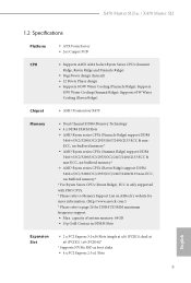
...; 2 x PCI Express 3.0 x16 Slots (single at x8 (PCIE1) / x8 (PCIE4))* * Supports NVMe SSD as boot disks • 4 x PCI Express 2.0 x1 Slots English 2 1.2 Specifications Platform • ATX Form Factor • ...Supports 105W Water Cooling (Pinnacle Ridge); Supports 65W Water Cooling (Raven Ridge) Chipset • AMD Promontory X470 Memory • Dual Channel DDR4 Memory Technology • 4 x DDR4 DIMM Slots • AMD .... * Please refer to Memory Support List on ASRock's website for more information. (http://www.asrock.com/) * Please refer to page 25 for DDR4 UDIMM maximum frequency support....
...; 2 x PCI Express 3.0 x16 Slots (single at x8 (PCIE1) / x8 (PCIE4))* * Supports NVMe SSD as boot disks • 4 x PCI Express 2.0 x1 Slots English 2 1.2 Specifications Platform • ATX Form Factor • ...Supports 105W Water Cooling (Pinnacle Ridge); Supports 65W Water Cooling (Raven Ridge) Chipset • AMD Promontory X470 Memory • Dual Channel DDR4 Memory Technology • 4 x DDR4 DIMM Slots • AMD .... * Please refer to Memory Support List on ASRock's website for more information. (http://www.asrock.com/) * Please refer to page 25 for DDR4 UDIMM maximum frequency support....
User Manual
Page 11
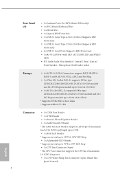
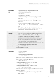
Rear Panel I/O • 2 x Antenna Ports (for X470 Master SLI/ac only) • 1 x PS/2 Mouse/Keyboard Port • 1 x HDMI Port • 1 x Optical SPDIF Out Port • 1 x USB 3.1 Gen2 Type-A Port (10 Gb/s) (Supports ESD Protection) • 1 x ...), supports M Key type 2230/2242/2260/2280 M.2 SATA3 6.0 Gb/s module and M.2 PCI Express module up to Gen2 x2 (10 Gb/s)* * Supports NVMe SSD as boot disks * Supports ASRock U.2 Kit Connector • 1 x COM Port Header • 1 x TPM Header • 1 x Power LED and Speaker Header • 1 x AMD Fan LED Header * The AMD Fan LED...
Rear Panel I/O • 2 x Antenna Ports (for X470 Master SLI/ac only) • 1 x PS/2 Mouse/Keyboard Port • 1 x HDMI Port • 1 x Optical SPDIF Out Port • 1 x USB 3.1 Gen2 Type-A Port (10 Gb/s) (Supports ESD Protection) • 1 x ...), supports M Key type 2230/2242/2260/2280 M.2 SATA3 6.0 Gb/s module and M.2 PCI Express module up to Gen2 x2 (10 Gb/s)* * Supports NVMe SSD as boot disks * Supports ASRock U.2 Kit Connector • 1 x COM Port Header • 1 x TPM Header • 1 x Power LED and Speaker Header • 1 x AMD Fan LED Header * The AMD Fan LED...
User Manual
Page 37
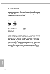
... jumper cap is placed on CLRCMOS1 for 15 seconds, use a jumper cap to clear the CMOS when you just finish updating the BIOS, you must boot up the system first, and then shut it down before you update the BIOS. Please be noted that the password, date, time, and user default...
... jumper cap is placed on CLRCMOS1 for 15 seconds, use a jumper cap to clear the CMOS when you just finish updating the BIOS, you must boot up the system first, and then shut it down before you update the BIOS. Please be noted that the password, date, time, and user default...

User Manual
Page 49
... driver updates. Please check AMD's website for details. AMD Catalyst Control Center Step 4 Double-click the AMD Catalyst Control Center icon in your computer and boot into OS. Select the GPU number according to your computer. Then select Enable AMD CrossFireX and click Apply. We recommend using this utility to installation...
... driver updates. Please check AMD's website for details. AMD Catalyst Control Center Step 4 Double-click the AMD Catalyst Control Center icon in your computer and boot into OS. Select the GPU number according to your computer. Then select Enable AMD CrossFireX and click Apply. We recommend using this utility to installation...

User Manual
Page 69
... time/date information OC Tweaker For overclocking configurations Advanced For advanced system configurations Tool Useful tools H/W Monitor Displays current hardware status Security For security settings Boot For configuring boot settings and boot priority Exit Exit the current screen or the UEFI Setup Utility English 62
... time/date information OC Tweaker For overclocking configurations Advanced For advanced system configurations Tool Useful tools H/W Monitor Displays current hardware status Security For security settings Boot For configuring boot settings and boot priority Exit Exit the current screen or the UEFI Setup Utility English 62

User Manual
Page 73
... Voltage Configure the voltage for the 2.50V PROM. +1.8 Voltage Use this to select +1.8 Voltage. VDDP Configure the voltage for the VPPM. AM4 Advance Boot Training Set TR4 Advance boot training to [Auto] to save your settings as user default. 66 English The default value is needed after selecting [Auto]. To re-enable...
... Voltage Configure the voltage for the 2.50V PROM. +1.8 Voltage Use this to select +1.8 Voltage. VDDP Configure the voltage for the VPPM. AM4 Advance Boot Training Set TR4 Advance boot training to [Auto] to save your settings as user default. 66 English The default value is needed after selecting [Auto]. To re-enable...

User Manual
Page 78
...boot up when the power recovers. Deep Sleep Configure deep sleep mode for power saving when the computer is installed. If [Power Off] is selected, the system will remain off when the power recovers. Front Panel Enable/disable front panel HD audio. X470 Master SLI/ac / X470 Master SLI... 4.4.3 South Bridge Configuration Onboard HD Audio Enable/disable onboard HD audio. Restore on AC/Power Loss Select the power state after a power failure. If [Power On] is...
...boot up when the power recovers. Deep Sleep Configure deep sleep mode for power saving when the computer is installed. If [Power Off] is selected, the system will remain off when the power recovers. Front Panel Enable/disable front panel HD audio. X470 Master SLI/ac / X470 Master SLI... 4.4.3 South Bridge Configuration Onboard HD Audio Enable/disable onboard HD audio. Restore on AC/Power Loss Select the power state after a power failure. If [Power On] is...

User Manual
Page 97
... section you may also clear the user password. Users are unable to remove the password. Leave it blank and press enter to support Secure Boot. 90 English Secure Boot Enable to remove the password. Leave it blank and press enter to change the settings in the UEFI Setup Utility. Only the administrator...
... section you may also clear the user password. Users are unable to remove the password. Leave it blank and press enter to support Secure Boot. 90 English Secure Boot Enable to remove the password. Leave it blank and press enter to change the settings in the UEFI Setup Utility. Only the administrator...

User Manual
Page 98
X470 Master SLI/ac / X470 Master SLI 4.8 Boot Screen This section displays the available devices on your computer's boot time. Boot From Onboard LAN Allow the system to show normal POST messages. 91 English Please note that a buzzer is needed. Fast Boot Fast Boot minimizes your system for the setup hot key. Boot Beep Select whether the Boot... Beep should be turned on or off when the system boots up. Full Screen Logo Enable to display the boot logo or disable to...
X470 Master SLI/ac / X470 Master SLI 4.8 Boot Screen This section displays the available devices on your computer's boot time. Boot From Onboard LAN Allow the system to show normal POST messages. 91 English Please note that a buzzer is needed. Fast Boot Fast Boot minimizes your system for the setup hot key. Boot Beep Select whether the Boot... Beep should be turned on or off when the system boots up. Full Screen Logo Enable to display the boot logo or disable to...

User Manual
Page 99
... configure the AddOn ROM if you 're running a WHCK test. CSM (Compatibility Support Module) CSM Enable to launch the Compatibility Support Module. Disable for faster boot speed.
... configure the AddOn ROM if you 're running a WHCK test. CSM (Compatibility Support Module) CSM Enable to launch the Compatibility Support Module. Disable for faster boot speed.
Quick Installation Guide
Page 13
...in DIMM Slots Expansion Slot • 2 x PCI Express 3.0 x16 Slots (single at x8 (PCIE1) / x8 (PCIE4))* * Supports NVMe SSD as boot disks • 4 x PCI Express 2.0 x1 Slots 9 English dual at x16 (PCIE1); Supports 95W Water Cooling (Summit Ridge); Supports 65W Water Cooling... with PRO CPUs. * Please refer to Memory Support List on ASRock's website for more information. (http://www.asrock.com/) * Please refer to page 26 for DDR4 UDIMM maximum frequency support. • Max. X470 Master SLI/ac / X470 Master SLI 1.2 Specifications Platform • ATX Form Factor • 2oz Copper...
...in DIMM Slots Expansion Slot • 2 x PCI Express 3.0 x16 Slots (single at x8 (PCIE1) / x8 (PCIE4))* * Supports NVMe SSD as boot disks • 4 x PCI Express 2.0 x1 Slots 9 English dual at x16 (PCIE1); Supports 95W Water Cooling (Summit Ridge); Supports 65W Water Cooling... with PRO CPUs. * Please refer to Memory Support List on ASRock's website for more information. (http://www.asrock.com/) * Please refer to page 26 for DDR4 UDIMM maximum frequency support. • Max. X470 Master SLI/ac / X470 Master SLI 1.2 Specifications Platform • ATX Form Factor • 2oz Copper...
Quick Installation Guide
Page 15
X470 Master SLI/ac / X470 Master SLI Rear Panel I/O • 2 x Antenna Ports (for X470 Master SLI/ac only) • 1 x PS/2 Mouse/Keyboard Port • 1 x HDMI Port • 1 x Optical SPDIF Out Port • 1 x USB 3.1 Gen2 Type-A Port (10 Gb/s) (Supports ESD Protection) &#...), supports M Key type 2230/2242/2260/2280 M.2 SATA3 6.0 Gb/s module and M.2 PCI Express module up to Gen2 x2 (10 Gb/s)* * Supports NVMe SSD as boot disks * Supports ASRock U.2 Kit Connector • 1 x COM Port Header • 1 x TPM Header • 1 x Power LED and Speaker Header • 1 x AMD Fan LED Header * ...
X470 Master SLI/ac / X470 Master SLI Rear Panel I/O • 2 x Antenna Ports (for X470 Master SLI/ac only) • 1 x PS/2 Mouse/Keyboard Port • 1 x HDMI Port • 1 x Optical SPDIF Out Port • 1 x USB 3.1 Gen2 Type-A Port (10 Gb/s) (Supports ESD Protection) &#...), supports M Key type 2230/2242/2260/2280 M.2 SATA3 6.0 Gb/s module and M.2 PCI Express module up to Gen2 x2 (10 Gb/s)* * Supports NVMe SSD as boot disks * Supports ASRock U.2 Kit Connector • 1 x COM Port Header • 1 x TPM Header • 1 x Power LED and Speaker Header • 1 x AMD Fan LED Header * ...

Quick Installation Guide
Page 34
... toremove the jumper cap after you update the BIOS. If you need to clear the CMOS when you just finish updating the BIOS, you must boot up the system first, and then shut it down before you to clear the data in CMOS. The illustration shows a 3-pin jumper whose pin1 and...
... toremove the jumper cap after you update the BIOS. If you need to clear the CMOS when you just finish updating the BIOS, you must boot up the system first, and then shut it down before you to clear the data in CMOS. The illustration shows a 3-pin jumper whose pin1 and...

