
User Manual
Page 8
... Fan Connector (4-pin) • 1 x Chassis Fan Connector (4-pin) • 1 x SATA Power Connector • 1 x Front Panel Audio Connector • 3 x USB 2.0 Headers (Support 5 USB 2.0 ports) (Supports ESD Protection (ASRock Full Spike Protection)) • 1 x USB 3.0 Header by Etron EJ188 (Supports 2 USB 3.0 ports) (Supports ESD Protection (ASRock Full Spike Protection)) • 64Mb AMI UEFI Legal BIOS with...® Windows® 8.1 32-bit / 8.1 64-bit / 8 32-bit / 8 64bit / 7 32-bit / 7 64-bit • FCC, CE, WHQL • ErP/EuP Ready (ErP/EuP ready power supply is required) English 4
... Fan Connector (4-pin) • 1 x Chassis Fan Connector (4-pin) • 1 x SATA Power Connector • 1 x Front Panel Audio Connector • 3 x USB 2.0 Headers (Support 5 USB 2.0 ports) (Supports ESD Protection (ASRock Full Spike Protection)) • 1 x USB 3.0 Header by Etron EJ188 (Supports 2 USB 3.0 ports) (Supports ESD Protection (ASRock Full Spike Protection)) • 64Mb AMI UEFI Legal BIOS with...® Windows® 8.1 32-bit / 8.1 64-bit / 8 32-bit / 8 64bit / 7 32-bit / 7 64-bit • FCC, CE, WHQL • ErP/EuP Ready (ErP/EuP ready power supply is required) English 4

User Manual
Page 16
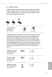
Before installing an expansion card, please make necessary hardware settings for the card before you start the installation. mini-PCIe slot: MINI_PCIE1 (mini-PCIe slot) is unplugged. Please read the documentation of the expansion card and make sure that the power supply is switched off or the power cord is used for PCI Express x4 lane width cards. PCIe slot: PCIE1 (PCIe 2.0 x4 slot) is 1 PCI Express slot and 1 mini PCI Express slot on this motherboard. 2.2 Expansion Slots (PCI Express Slots) There is used for WiFi module. 12 English
Before installing an expansion card, please make necessary hardware settings for the card before you start the installation. mini-PCIe slot: MINI_PCIE1 (mini-PCIe slot) is unplugged. Please read the documentation of the expansion card and make sure that the power supply is switched off or the power cord is used for PCI Express x4 lane width cards. PCIe slot: PCIE1 (PCIe 2.0 x4 slot) is 1 PCI Express slot and 1 mini PCI Express slot on this motherboard. 2.2 Expansion Slots (PCI Express Slots) There is used for WiFi module. 12 English
User Manual
Page 17
...default setup, please turn off the computer and unplug the power cord from the power supply. Backlight Power Jumper (3-pin BKT_PWR1) (see p.5, No. 12) 1-2 : +19V 2-3 : +12V Panel Power Jumper (3-pin PNL_PWR1) (see p.5, No. 14) 1-2 : +3V 2-3 : +5V Digital Input / Output Power Selection Jumper (see p.5, No. 20) Default Clear CMOS...password, date, time, and user default profile will be cleared only if the CMOS battery is placed on CLRCMOS1 for 5 seconds. Q1900TM-ITX 2.5 Jumpers Setup The illustration shows how jumpers are "Short" when a jumper cap is placed on the pins, the jumper is "...
...default setup, please turn off the computer and unplug the power cord from the power supply. Backlight Power Jumper (3-pin BKT_PWR1) (see p.5, No. 12) 1-2 : +19V 2-3 : +12V Panel Power Jumper (3-pin PNL_PWR1) (see p.5, No. 14) 1-2 : +3V 2-3 : +5V Digital Input / Output Power Selection Jumper (see p.5, No. 20) Default Clear CMOS...password, date, time, and user default profile will be cleared only if the CMOS battery is placed on CLRCMOS1 for 5 seconds. Q1900TM-ITX 2.5 Jumpers Setup The illustration shows how jumpers are "Short" when a jumper cap is placed on the pins, the jumper is "...

Quick Installation Guide
Page 9
...Fan Connector (4-pin) • 1 x SATA Power Connector • 1 x Front Panel Audio Connector • 3 x USB 2.0 Headers (Support 5 USB 2.0 ports) (Supports ESD Protection (ASRock Full Spike Protection)) • 1 x USB 3.0 Header by Etron EJ188 (Supports 2 USB 3.0 ports) (Supports ESD Protection (ASRock Full Spike Protection)) BIOS Feature • 64Mb ...bit / 8 64- bit / 7 32-bit / 7 64-bit Certifications • FCC, CE, WHQL • ErP/EuP Ready (ErP/EuP ready power supply is required) * For detailed product information, please visit our website: http://www.asrock.com English 8
...Fan Connector (4-pin) • 1 x SATA Power Connector • 1 x Front Panel Audio Connector • 3 x USB 2.0 Headers (Support 5 USB 2.0 ports) (Supports ESD Protection (ASRock Full Spike Protection)) • 1 x USB 3.0 Header by Etron EJ188 (Supports 2 USB 3.0 ports) (Supports ESD Protection (ASRock Full Spike Protection)) BIOS Feature • 64Mb ...bit / 8 64- bit / 7 32-bit / 7 64-bit Certifications • FCC, CE, WHQL • ErP/EuP Ready (ErP/EuP ready power supply is required) * For detailed product information, please visit our website: http://www.asrock.com English 8
Quick Installation Guide
Page 13
PCIe slot: PCIE1 (PCIe 2.0 x4 slot) is used for the card before you start the installation. mini-PCIe slot: MINI_PCIE1 (mini-PCIe slot) is used for WiFi module. 12 English 2.2 Expansion Slots (PCI Express Slots) There is unplugged. Before installing an expansion card, please make necessary hardware settings for PCI Express x4 lane width cards. Please read the documentation of the expansion card and make sure that the power supply is switched off or the power cord is 1 PCI Express slot and 1 mini PCI Express slot on this motherboard.
PCIe slot: PCIE1 (PCIe 2.0 x4 slot) is used for the card before you start the installation. mini-PCIe slot: MINI_PCIE1 (mini-PCIe slot) is used for WiFi module. 12 English 2.2 Expansion Slots (PCI Express Slots) There is unplugged. Before installing an expansion card, please make necessary hardware settings for PCI Express x4 lane width cards. Please read the documentation of the expansion card and make sure that the power supply is switched off or the power cord is 1 PCI Express slot and 1 mini PCI Express slot on this motherboard.

Quick Installation Guide
Page 14
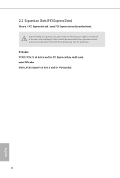
... is "Open". To clear and reset the system parameters to clear the data in CMOS. When the jumper cap is placed on CLRCMOS1 for 5 seconds. Q1900TM-ITX 2.5 Jumpers Setup The illustration shows how jumpers are "Short" when a jumper cap is placed on these 2 pins. If no jumper cap is placed on the... then shut it down before you do not clear the CMOS right after you to default setup, please turn off the computer and unplug the power cord from the power supply. The illustration shows a 3-pin jumper whose pin1 and pin2 are setup.
... is "Open". To clear and reset the system parameters to clear the data in CMOS. When the jumper cap is placed on CLRCMOS1 for 5 seconds. Q1900TM-ITX 2.5 Jumpers Setup The illustration shows how jumpers are "Short" when a jumper cap is placed on these 2 pins. If no jumper cap is placed on the... then shut it down before you do not clear the CMOS right after you to default setup, please turn off the computer and unplug the power cord from the power supply. The illustration shows a 3-pin jumper whose pin1 and pin2 are setup.

