User Manual
Page 7
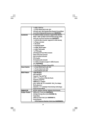
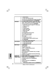
...CAUTION 8) - 1 x Dr. Debug (7-Segment Debug LED) - 1 x Clear CMOS Switch with LED - 1 x Power Switch with LED - 1 x Reset Switch with LED - Instant Boot - Front panel audio connector - 3 x USB 2.0 headers (support 6 USB 2.0 ports) (see CAUTION 10) - CPU ...1394 Port - 1 x Clear CMOS Switch with LED - 16Mb AMI BIOS - Supports jumperfree - ASRock Instant Flash (see CAUTION 12) 7 Hybrid Booster: - Supports I. Supports Smart BIOS - Drivers, Utilities, AntiVirus Software (Trial Version) - ASRock OC Tuner (see CAUTION 7) - 1 x ATA133 IDE connector (supports 2 x IDE devices)...
...CAUTION 8) - 1 x Dr. Debug (7-Segment Debug LED) - 1 x Clear CMOS Switch with LED - 1 x Power Switch with LED - 1 x Reset Switch with LED - Instant Boot - Front panel audio connector - 3 x USB 2.0 headers (support 6 USB 2.0 ports) (see CAUTION 10) - CPU ...1394 Port - 1 x Clear CMOS Switch with LED - 16Mb AMI BIOS - Supports jumperfree - ASRock Instant Flash (see CAUTION 12) 7 Hybrid Booster: - Supports I. Supports Smart BIOS - Drivers, Utilities, AntiVirus Software (Trial Version) - ASRock OC Tuner (see CAUTION 7) - 1 x ATA133 IDE connector (supports 2 x IDE devices)...

User Manual
Page 11
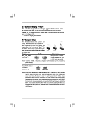
...SPK Center: REAR SPK FRONT Bottom: CTR BASS MIC IN Top: LINE IN Center: Bottom: 36 LAN PHY 35 PWR_FAN1 CPU_FAN1 1394a CrossFireX PCIE1 P55 Pro EuP Ready PCI Express 2.0 PCIE2 Dual Channel CHA_FAN3 34 33 32 31 Super I/O PCIE3 PCIE4 AUDIO CODEC RoHS HD_AUDIO1 CD1 COM1 1 1 1 HDMI_SPDIF1...JMB363 VIA VT6308S 1 CLRCMOS1 16Mb BIOS CMOS Battery Dr. Debug RSTBTN FRONT_1394 USB8_9 TPM1 USB10_11 USB12_13 1 PLED PWRBTN PWRBTN 1 1 1 1 1 HDLED RESET 1 IR1 PANEL1 26 25 24 23 22 SATAII_5_6 SATAII_3_4 SATAII_1_2 7 8 9 10 11 12 13 14 15 16 17 18 19 20 21 1 ...
...SPK Center: REAR SPK FRONT Bottom: CTR BASS MIC IN Top: LINE IN Center: Bottom: 36 LAN PHY 35 PWR_FAN1 CPU_FAN1 1394a CrossFireX PCIE1 P55 Pro EuP Ready PCI Express 2.0 PCIE2 Dual Channel CHA_FAN3 34 33 32 31 Super I/O PCIE3 PCIE4 AUDIO CODEC RoHS HD_AUDIO1 CD1 COM1 1 1 1 HDMI_SPDIF1...JMB363 VIA VT6308S 1 CLRCMOS1 16Mb BIOS CMOS Battery Dr. Debug RSTBTN FRONT_1394 USB8_9 TPM1 USB10_11 USB12_13 1 PLED PWRBTN PWRBTN 1 1 1 1 1 HDLED RESET 1 IR1 PANEL1 26 25 24 23 22 SATAII_5_6 SATAII_3_4 SATAII_1_2 7 8 9 10 11 12 13 14 15 16 17 18 19 20 21 1 ...
User Manual
Page 24
... is placed on these 2 pins. Clear CMOS Jumper (CLRCMOS1) (see p.11, No. 1) 2_3 Short pin2, pin3 to clear the data in CMOS. To clear and reset the system parameters to the document at the following path in CMOS includes system setup information such as system password, date, time, and system setup...
... is placed on these 2 pins. Clear CMOS Jumper (CLRCMOS1) (see p.11, No. 1) 2_3 Short pin2, pin3 to clear the data in CMOS. To clear and reset the system parameters to the document at the following path in CMOS includes system setup information such as system password, date, time, and system setup...

User Manual
Page 28
...) GND +12V CHA_FAN_SPEED (3-pin PWR_FAN1) (see p.11 No. 38) PWR_FAN_SPEED +12V GND CPU Fan Connector (4-pin CPU_FAN1) (see p.11 No. 22) PLED+ PLEDPWRBTN# GND 1 DUMMY RESET# GND HDLEDHDLED+ This header accommodates several system front panel functions. System Panel Header (9-pin PANEL1) (see p.11 No. 37) FAN_SPEED_CONTROL 4 CPU_FAN_SPEED 3 +12V 2 GND 1 Please connect...
...) GND +12V CHA_FAN_SPEED (3-pin PWR_FAN1) (see p.11 No. 38) PWR_FAN_SPEED +12V GND CPU Fan Connector (4-pin CPU_FAN1) (see p.11 No. 22) PLED+ PLEDPWRBTN# GND 1 DUMMY RESET# GND HDLEDHDLED+ This header accommodates several system front panel functions. System Panel Header (9-pin PANEL1) (see p.11 No. 37) FAN_SPEED_CONTROL 4 CPU_FAN_SPEED 3 +12V 2 GND 1 Please connect...

User Manual
Page 31
... instead. 31 Clear CMOS Switch (CLRCBTN) (see p.11 No. 20) Power Switch is a smart switch, allowing users to quickly turn on /off or reset the system or clear the CMOS values. If you set up the system password. 2.11 Smart Switches This motherboard has three smart switches: power switch..., reset switch and clear CMOS switch, allowing users to quickly turn on /off the system. Power Switch (PWRBTN) (see p.12 No. 17) clr CMOS...
... instead. 31 Clear CMOS Switch (CLRCBTN) (see p.11 No. 20) Power Switch is a smart switch, allowing users to quickly turn on /off or reset the system or clear the CMOS values. If you set up the system password. 2.11 Smart Switches This motherboard has three smart switches: power switch..., reset switch and clear CMOS switch, allowing users to quickly turn on /off the system. Power Switch (PWRBTN) (see p.12 No. 17) clr CMOS...

User Manual
Page 48
... the current screen or the BIOS SETUP UTILITY Use < > key or < > key to choose among the selections on . You may also restart by pressing the reset button on the motherboard stores the BIOS SETUP UTILITY. Chapter 3: BIOS SETUP UTILITY 3.1 Introduction This section explains how to use the BIOS SETUP UTILITY to...
... the current screen or the BIOS SETUP UTILITY Use < > key or < > key to choose among the selections on . You may also restart by pressing the reset button on the motherboard stores the BIOS SETUP UTILITY. Chapter 3: BIOS SETUP UTILITY 3.1 Introduction This section explains how to use the BIOS SETUP UTILITY to...
Quick Installation Guide
Page 2
... Connector (SATAII_3_4, Red) 11 SATAII Connector (SATAII_5_6, Red) 12 Chassis Fan Connector (CHA_FAN3) 13 Intel P55 Chipset 14 Primary IDE Connector (IDE1, Blue) 15 Clear CMOS Jumper (CLRCMOS1) 16 16Mb SPI Flash 17 Dr. Debug 18 Reset Switch (RSTBTN) 19 TPM Header (TPM1) 20 Power Switch (PWRBTN) 21 Infrared Module Header (IR1..., White) 35 PCI Express 2.0 x16 Slot (PCIE2, Blue) 36 PCI Express 2.0 x1 Slot (PCIE1, White) 37 CPU Fan Connector (CPU_FAN1) 38 Power Fan Connector (PWR_FAN1) 2 ASRock P55 Pro Motherboard
... Connector (SATAII_3_4, Red) 11 SATAII Connector (SATAII_5_6, Red) 12 Chassis Fan Connector (CHA_FAN3) 13 Intel P55 Chipset 14 Primary IDE Connector (IDE1, Blue) 15 Clear CMOS Jumper (CLRCMOS1) 16 16Mb SPI Flash 17 Dr. Debug 18 Reset Switch (RSTBTN) 19 TPM Header (TPM1) 20 Power Switch (PWRBTN) 21 Infrared Module Header (IR1..., White) 35 PCI Express 2.0 x16 Slot (PCIE2, Blue) 36 PCI Express 2.0 x1 Slot (PCIE1, White) 37 CPU Fan Connector (CPU_FAN1) 38 Power Fan Connector (PWR_FAN1) 2 ASRock P55 Pro Motherboard
Quick Installation Guide
Page 6
..., SB, VTT, VCCM REF, PCH_PLL Voltage Multi-adjustment - Drivers, Utilities, AntiVirus Software (Trial Version) Unique Feature - ASRock Instant Flash (see CAUTION 12) 6 ASRock P55 Pro Motherboard CPU Frequency Stepless Control (see CAUTION 11) - O. T. (Intelligent Overclocking Technology) English - Hybrid Booster: - Supports...Debug LED) Smart Switch - 1 x Clear CMOS Switch with LED - 1 x Power Switch with LED - 1 x Reset Switch with LED - ASRock OC Tuner (see CAUTION 10) - - 1 x IEEE 1394 Port - 1 x Clear CMOS Switch with LED BIOS Feature - 16Mb AMI BIOS -...
..., SB, VTT, VCCM REF, PCH_PLL Voltage Multi-adjustment - Drivers, Utilities, AntiVirus Software (Trial Version) Unique Feature - ASRock Instant Flash (see CAUTION 12) 6 ASRock P55 Pro Motherboard CPU Frequency Stepless Control (see CAUTION 11) - O. T. (Intelligent Overclocking Technology) English - Hybrid Booster: - Supports...Debug LED) Smart Switch - 1 x Clear CMOS Switch with LED - 1 x Power Switch with LED - 1 x Reset Switch with LED - ASRock OC Tuner (see CAUTION 10) - - 1 x IEEE 1394 Port - 1 x Clear CMOS Switch with LED BIOS Feature - 16Mb AMI BIOS -...

Quick Installation Guide
Page 20
... Setting Description PS2_USB_PWR1 Short pin2, pin3 to clear the CMOS when you just finish updating the BIOS, you must boot up events. To clear and reset the system parameters to the document at the following path in CMOS includes system setup information such as system password, date, time, and system setup... for PS/2 or USB wake up the system first, and then shut it requires 2 Amp and higher standby current provided by power supply. English 20 ASRock P55 Pro Motherboard
... Setting Description PS2_USB_PWR1 Short pin2, pin3 to clear the CMOS when you just finish updating the BIOS, you must boot up events. To clear and reset the system parameters to the document at the following path in CMOS includes system setup information such as system password, date, time, and system setup... for PS/2 or USB wake up the system first, and then shut it requires 2 Amp and higher standby current provided by power supply. English 20 ASRock P55 Pro Motherboard

Quick Installation Guide
Page 26
...) (see p.2 No. 18) Reset Switch is a smart switch, allowing users to the HDMI_SPDIF header on the motherboard. English 26 ASRock P55 Pro Motherboard B. black end C B A Please connect the black end (A) of HDMI VGA card. Power Switch (PWRBTN) (see p.3 No. 17) Clear CMOS Switch is a ...not allowed to quickly turn on /off the system. white end (3-pin) 2.9 Smart Switches This motherboard has three smart switches: power switch, reset switch and clear CMOS switch, allowing users to use Clear CMOS switch function if you want to clear the CMOS values, please clean your system...
...) (see p.2 No. 18) Reset Switch is a smart switch, allowing users to the HDMI_SPDIF header on the motherboard. English 26 ASRock P55 Pro Motherboard B. black end C B A Please connect the black end (A) of HDMI VGA card. Power Switch (PWRBTN) (see p.3 No. 17) Clear CMOS Switch is a ...not allowed to quickly turn on /off the system. white end (3-pin) 2.9 Smart Switches This motherboard has three smart switches: power switch, reset switch and clear CMOS switch, allowing users to use Clear CMOS switch function if you want to clear the CMOS values, please clean your system...

Quick Installation Guide
Page 32
... computer, please press during the Power-On-Self-Test (POST) to enter BIOS Setup after POST, please restart the system by pressing + + , or pressing the reset button on the system chassis. The Support CD that will display the Main Menu automatically if "AUTORUN" is designed to select among the predetermined choices... the User Manual (PDF file) contained in your CD-ROM drive. For the detailed information about BIOS Setup, please refer to display the menus. 32 ASRock P55 Pro Motherboard English 3.
... computer, please press during the Power-On-Self-Test (POST) to enter BIOS Setup after POST, please restart the system by pressing + + , or pressing the reset button on the system chassis. The Support CD that will display the Main Menu automatically if "AUTORUN" is designed to select among the predetermined choices... the User Manual (PDF file) contained in your CD-ROM drive. For the detailed information about BIOS Setup, please refer to display the menus. 32 ASRock P55 Pro Motherboard English 3.


