
Intel Rapid Storage Guide
Page 12
... Operation Mode option to save the BIOS settings and exit the BIOS Setup program. Enable RAID in System BIOS Use the instructions included with your motherboard to enter the BIOS Setup program after the Power-On-Self-Test (POST) memory test begins. 2. The F6 installation method is not required for Microsoft...
... Operation Mode option to save the BIOS settings and exit the BIOS Setup program. Enable RAID in System BIOS Use the instructions included with your motherboard to enter the BIOS Setup program after the Power-On-Self-Test (POST) memory test begins. 2. The F6 installation method is not required for Microsoft...

RAID Installation Guide
Page 2
... of "User Manual" in this motherboard for internal storage devices. For SATA installation guide, please refer to create RAID on this guide carefully according to SATA Hard Disks Installation 1.1 Serial ATA (SATA) Hard Disks Installation Intel P55 chipset supports Serial ATA (SATA) ...hard disks with RAID functions, including RAID 0, RAID 1, RAID 10, RAID 5, and Intel Rapid Storage. Guide to the Intel southbridge chipset that your motherboard adopts. Please read the RAID configurations in the...
... of "User Manual" in this motherboard for internal storage devices. For SATA installation guide, please refer to create RAID on this guide carefully according to SATA Hard Disks Installation 1.1 Serial ATA (SATA) Hard Disks Installation Intel P55 chipset supports Serial ATA (SATA) ...hard disks with RAID functions, including RAID 0, RAID 1, RAID 10, RAID 5, and Intel Rapid Storage. Guide to the Intel southbridge chipset that your motherboard adopts. Please read the RAID configurations in the...

RAID Installation Guide
Page 3
... fault tolerance to the surviving drive as a single drive but at a sustained data transfer rate. For optimal performance, please install identical drives of RAID This motherboard adopts Intel southbridge chipset that integrates RAID controller supporting RAID 0 / RAID 1/ Intel Rapid Storage / RAID 10 / RAID 5 function with four independent Serial ATA (SATA) channels...
... fault tolerance to the surviving drive as a single drive but at a sustained data transfer rate. For optimal performance, please install identical drives of RAID This motherboard adopts Intel southbridge chipset that integrates RAID controller supporting RAID 0 / RAID 1/ Intel Rapid Storage / RAID 10 / RAID 5 function with four independent Serial ATA (SATA) channels...

RAID Installation Guide
Page 8
... to a RAID 0 volume, use Disk Management from Existing Hard Drive Wizard. To prepare for this, you will need another SATA / SATAII hard drive with your motherboard or after downloading it as prompted. Click through the dialogs as the source hard drive when initiating the migration. 2. You may also use this to...
... to a RAID 0 volume, use Disk Management from Existing Hard Drive Wizard. To prepare for this, you will need another SATA / SATAII hard drive with your motherboard or after downloading it as prompted. Click through the dialogs as the source hard drive when initiating the migration. 2. You may also use this to...

User Manual
Page 2
... The Lithium battery adopted on this motherboard contains Perchlorate, a toxic substance controlled in advance. "Perchlorate Material-special handling may apply, see www.dtsc.ca.gov/hazardouswaste/perchlorate" ASRock Website: http://www.asrock.com 2 ASRock assumes no event shall ASRock, its directors, officers, employees, ...Perchlorate Best Management Practices (BMP) regulations passed by the California Legislature. With respect to the contents of this manual, ASRock does not provide warranty of any kind, either expressed or implied, including but not limited to change without notice, ...
... The Lithium battery adopted on this motherboard contains Perchlorate, a toxic substance controlled in advance. "Perchlorate Material-special handling may apply, see www.dtsc.ca.gov/hazardouswaste/perchlorate" ASRock Website: http://www.asrock.com 2 ASRock assumes no event shall ASRock, its directors, officers, employees, ...Perchlorate Best Management Practices (BMP) regulations passed by the California Legislature. With respect to the contents of this manual, ASRock does not provide warranty of any kind, either expressed or implied, including but not limited to change without notice, ...
User Manual
Page 3
Contents 1 Introduction 5 1.1 Package Contents 5 1.2 Specifications 6 1.3 Two SLITM Graphics Card Support List 11 1.4 Two CrossFireXTM Graphics Card Support List 11 1.5 Motherboard Layout 12 1.6 I/O Panel 13 2 Installation 15 2.1 Screw Holes 15 2.2 Pre-installation Precautions 15 2.3 CPU Installation 16 2.4 Installation of Heatsink and CPU fan 18 2.5 Installation of ...
Contents 1 Introduction 5 1.1 Package Contents 5 1.2 Specifications 6 1.3 Two SLITM Graphics Card Support List 11 1.4 Two CrossFireXTM Graphics Card Support List 11 1.5 Motherboard Layout 12 1.6 I/O Panel 13 2 Installation 15 2.1 Screw Holes 15 2.2 Pre-installation Precautions 15 2.3 CPU Installation 16 2.4 Installation of Heatsink and CPU fan 18 2.5 Installation of ...

User Manual
Page 5
... change without further notice. Chapter 1: Introduction Thank you for a 3.5-in , 30.5 cm x 24.4 cm) ASRock P55 Deluxe3 Quick Installation Guide ASRock P55 Deluxe3 Support CD 1 x 80-conductor Ultra ATA 66/100/133 IDE Ribbon Cable 1 x Ribbon Cable for purchasing ASRock P55 Deluxe3 motherboard, a reliable motherboard produced under ASRock's consistently stringent quality control. Chapter 3 and 4 contain the configuration guide to BIOS setup and...
... change without further notice. Chapter 1: Introduction Thank you for a 3.5-in , 30.5 cm x 24.4 cm) ASRock P55 Deluxe3 Quick Installation Guide ASRock P55 Deluxe3 Support CD 1 x 80-conductor Ultra ATA 66/100/133 IDE Ribbon Cable 1 x Ribbon Cable for purchasing ASRock P55 Deluxe3 motherboard, a reliable motherboard produced under ASRock's consistently stringent quality control. Chapter 3 and 4 contain the configuration guide to BIOS setup and...
User Manual
Page 9
Please read the installation guide of memory modules on page 19 for the operation procedures of ASRock OC Tuner. This motherboard supports Dual Channel Memory Technology. Please check the table on page 52 for proper connection. 7. Featuring an advanced proprietary ...-bit / 7 / VistaTM 64-bit / VistaTM / XP 64-bit / XP SP1 or SP2. 8. For audio output, this motherboard supports both stereo and mono modes. ASRock website: http://www.asrock.com/feature/OCTuner/index.htm 9. In other complicated flash utility. This convenient BIOS update tool allows you can update your BIOS...
Please read the installation guide of memory modules on page 19 for the operation procedures of ASRock OC Tuner. This motherboard supports Dual Channel Memory Technology. Please check the table on page 52 for proper connection. 7. Featuring an advanced proprietary ...-bit / 7 / VistaTM 64-bit / VistaTM / XP 64-bit / XP SP1 or SP2. 8. For audio output, this motherboard supports both stereo and mono modes. ASRock website: http://www.asrock.com/feature/OCTuner/index.htm 9. In other complicated flash utility. This convenient BIOS update tool allows you can update your BIOS...

User Manual
Page 10
... the OC profile to their own system to record the OC settings and share with others. OC DNA, an exclusive utility developed by ASRock, provides a convenient way for Energy Using Product, was a provision regulated by European Union to Intel's suggestion, the EuP ready power ... selection, we recommend you what it back again. Combo Cooler Option (C.C.O.) provides the flexible option to perform over-clocking. Although this motherboard offers stepless control, it is higher than the recommended CPU bus frequencies may cause the instability of overclocking settings. According to EuP, ...
... the OC profile to their own system to record the OC settings and share with others. OC DNA, an exclusive utility developed by ASRock, provides a convenient way for Energy Using Product, was a provision regulated by European Union to Intel's suggestion, the EuP ready power ... selection, we recommend you what it back again. Combo Cooler Option (C.C.O.) provides the flexible option to perform over-clocking. Although this motherboard offers stepless control, it is higher than the recommended CPU bus frequencies may cause the instability of overclocking settings. According to EuP, ...
User Manual
Page 12
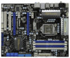
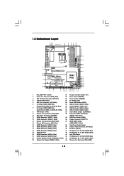
Clr CMOS 1.5 Motherboard Layout 12 3 24.4cm (9.6 in) PS2 Mouse PS2 Keyboard 1 PS2_USB_PWR1...39 38 PCIE1 LAN PHY PCIE2 CHA_FAN3 CHA_FAN2 IDE1 EuP Ready SATA3 6Gb/s SATAII_5_6 SATAII_3_4 SATAII_1_2 PCIE3 Super I/O P55 Deluxe3 Intel P55 PCIE4 PCI Express 2.0 1394a AUDIO CODEC HD_AUDIO1 1 CD1 HDMI_SPDIF1 1 FLOPPY1 PCI1 RoHS PCI2 COM1 1 CMOS ...19 16Mb SPI Flash 42 PCI Express 2.0 x1 Slot (PCIE3, White) 20 SATAII Connector (SATAII_5, Blue ) 43 Intel P55 Chipset 21 SATAII Connector (SATAII_6, Blue ) 44 PCI Express 2.0 x16 Slot (PCIE2, Blue) 22 Chassis Speaker Header (...
Clr CMOS 1.5 Motherboard Layout 12 3 24.4cm (9.6 in) PS2 Mouse PS2 Keyboard 1 PS2_USB_PWR1...39 38 PCIE1 LAN PHY PCIE2 CHA_FAN3 CHA_FAN2 IDE1 EuP Ready SATA3 6Gb/s SATAII_5_6 SATAII_3_4 SATAII_1_2 PCIE3 Super I/O P55 Deluxe3 Intel P55 PCIE4 PCI Express 2.0 1394a AUDIO CODEC HD_AUDIO1 1 CD1 HDMI_SPDIF1 1 FLOPPY1 PCI1 RoHS PCI2 COM1 1 CMOS ...19 16Mb SPI Flash 42 PCI Express 2.0 x1 Slot (PCIE3, White) 20 SATAII Connector (SATAII_5, Blue ) 43 Intel P55 Chipset 21 SATAII Connector (SATAII_6, Blue ) 44 PCI Express 2.0 x16 Slot (PCIE2, Blue) 22 Chassis Speaker Header (...

User Manual
Page 15
... the power cord is an ATX form factor (12.0" x 9.6", 30.5 x 24.4 cm) motherboard. Failure to do so may damage the motherboard. 2.2 Pre-installation Precautions Take note of your motherboard directly on a grounded antistatic pad or in the bag that comes with the component. Chapter 2: ...remember to do not touch the ICs. 4. Before you uninstall any motherboard settings. 1. Whenever you install the motherboard, study the configuration of the following precautions before touching any component, ensure that the motherboard fits into the holes indicated by the edges and do so may ...
... the power cord is an ATX form factor (12.0" x 9.6", 30.5 x 24.4 cm) motherboard. Failure to do so may damage the motherboard. 2.2 Pre-installation Precautions Take note of your motherboard directly on a grounded antistatic pad or in the bag that comes with the component. Chapter 2: ...remember to do not touch the ICs. 4. Before you uninstall any motherboard settings. 1. Whenever you install the motherboard, study the configuration of the following precautions before touching any component, ensure that the motherboard fits into the holes indicated by the edges and do so may ...

User Manual
Page 16
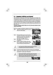
... tab. Step 2. This cap must be seriously damaged. Step 1. Remove PnP Cap (Pick and Place Cap). 1. Otherwise, the CPU will be placed if returning the motherboard for after service. 16 Step 1-2. Step 1-3. Disengaging the lever by depressing down and out on the socket. Load Plate Load Lever Contact Array Socket Body...
... tab. Step 2. This cap must be seriously damaged. Step 1. Remove PnP Cap (Pick and Place Cap). 1. Otherwise, the CPU will be placed if returning the motherboard for after service. 16 Step 1-2. Step 1-3. Disengaging the lever by depressing down and out on the socket. Load Plate Load Lever Contact Array Socket Body...
User Manual
Page 18
...Step 1. Secure excess cable with each other components. Apply Thermal Interface Material Step 2. Apply thermal interface material onto center of IHS on the motherboard (CPU_FAN1, see page 12, No. 5). Ensure fan cables are securely fastened and in good contact with tie-wrap to improve heat dissipation. ...heatsink to ensure cable does not interfere with Intel 1156-Pin CPU to dissipate heat. 2.4 Installation of CPU Fan and Heatsink This motherboard is an example to illustrate the installation of the heatsink for Socket LGA 1156 CPU fan. 18 Then connect the CPU fan ...
...Step 1. Secure excess cable with each other components. Apply Thermal Interface Material Step 2. Apply thermal interface material onto center of IHS on the motherboard (CPU_FAN1, see page 12, No. 5). Ensure fan cables are securely fastened and in good contact with tie-wrap to improve heat dissipation. ...heatsink to ensure cable does not interfere with Intel 1156-Pin CPU to dissipate heat. 2.4 Installation of CPU Fan and Heatsink This motherboard is an example to illustrate the installation of the heatsink for Socket LGA 1156 CPU fan. 18 Then connect the CPU fan ...

User Manual
Page 19
... Memory Configuration Table below. If only one memory module or three memory modules are installed in the DDR3 DIMM slots on this motherboard and DIMM may refer to install them either in the slots of white slots (DDR3_A1 and DDR3_B1). 2. Populated (2)* Populated Populated...Populated Populated * For the configuration (2), please install identical DDR3 DIMMs in Dual Channel (DDR3_A1 and DDR3_B1; You may be activated. This motherboard also allows you want to install identical DDR3 DIMM pair in all four slots. For dual channel configuration, you have to install two ...
... Memory Configuration Table below. If only one memory module or three memory modules are installed in the DDR3 DIMM slots on this motherboard and DIMM may refer to install them either in the slots of white slots (DDR3_A1 and DDR3_B1). 2. Populated (2)* Populated Populated...Populated Populated * For the configuration (2), please install identical DDR3 DIMMs in Dual Channel (DDR3_A1 and DDR3_B1; You may be activated. This motherboard also allows you want to install identical DDR3 DIMM pair in all four slots. For dual channel configuration, you have to install two ...

User Manual
Page 20
... break notch break The DIMM only fits in place and the DIMM is properly seated. 20 Step 1. Step 3. Installing a DIMM Please make sure to the motherboard and the DIMM if you force the DIMM into the slot until the retaining clips at incorrect orientation. Step 2. It will cause permanent damage to...
... break notch break The DIMM only fits in place and the DIMM is properly seated. 20 Step 1. Step 3. Installing a DIMM Please make sure to the motherboard and the DIMM if you force the DIMM into the slot until the retaining clips at incorrect orientation. Step 2. It will cause permanent damage to...

User Manual
Page 21
... support CrossFireXTM or SLITM function. 1. PCIE slots: PCIE1 / PCIE3 (PCIE x1 slot; In single VGA card mode, it is completely seated on this motherboard. Step 3. PCI slots: PCI slots are 2 PCI slots and 4 PCI Express slots on the slot. Please read the documentation of the expansion card.... Replace the system cover. 21 PCIE2 / PCIE4 (PCIE x16 slot; Step 2. White) is unplugged. Remove the system unit cover (if your motherboard is used to install PCI Express graphics cards to install a PCI Express x16 graphics card on PCIE2 and PCIE4 slots. Please connect a chassis fan ...
... support CrossFireXTM or SLITM function. 1. PCIE slots: PCIE1 / PCIE3 (PCIE x1 slot; In single VGA card mode, it is completely seated on this motherboard. Step 3. PCI slots: PCI slots are 2 PCI slots and 4 PCI Express slots on the slot. Please read the documentation of the expansion card.... Replace the system cover. 21 PCIE2 / PCIE4 (PCIE x16 slot; Step 2. White) is unplugged. Remove the system unit cover (if your motherboard is used to install PCI Express graphics cards to install a PCI Express x16 graphics card on PCIE2 and PCIE4 slots. Please connect a chassis fan ...

User Manual
Page 22
... refer to two identical PCI Express x16 graphics cards. Make sure that the cards are NVIDIA® certified. 2. 2.7 SLITM and Quad SLITM Operation Guide This motherboard supports NVIDIA® SLITM and Quad SLITM (Scalable Link Interface) technology that allows you should have two identical SLITM-ready graphics cards that are properly...
... refer to two identical PCI Express x16 graphics cards. Make sure that the cards are NVIDIA® certified. 2. 2.7 SLITM and Quad SLITM Operation Guide This motherboard supports NVIDIA® SLITM and Quad SLITM (Scalable Link Interface) technology that allows you should have two identical SLITM-ready graphics cards that are properly...

User Manual
Page 26
... Quad CrossFireXTM feature are properly seated on the slots. 26 All three CrossFireXTM components, a CrossFireXTM Ready graphics card, a CrossFireXTM Ready motherboard and a CrossFireXTM Edition co-processor graphics card, must be installed correctly to enable CrossFireXTM feature. For other Radeon graphics card to ATITM ... card, both cards will release in any 3D application. 2.8 CrossFireXTM and Quad CrossFireXTM Operation Guide This motherboard supports CrossFireXTM and Quad CrossFireXTM feature. If you pair a 12-pipe CrossFireXTM Edition card with Service Pack 2 / VistaTM / 7 OS.
... Quad CrossFireXTM feature are properly seated on the slots. 26 All three CrossFireXTM components, a CrossFireXTM Ready graphics card, a CrossFireXTM Ready motherboard and a CrossFireXTM Edition co-processor graphics card, must be installed correctly to enable CrossFireXTM feature. For other Radeon graphics card to ATITM ... card, both cards will release in any 3D application. 2.8 CrossFireXTM and Quad CrossFireXTM Operation Guide This motherboard supports CrossFireXTM and Quad CrossFireXTM feature. If you pair a 12-pipe CrossFireXTM Edition card with Service Pack 2 / VistaTM / 7 OS.

User Manual
Page 27
... the Radeon graphics card on the top of Radeon graphics cards. (CrossFire Bridge is provided with the graphics card you purchase, not bundled with this motherboard. Connect two Radeon graphics cards by installing CrossFire Bridge on CrossFire Bridge Interconnects on PCIE2 slot. (You may use the DVI to D-Sub adapter to...
... the Radeon graphics card on the top of Radeon graphics cards. (CrossFire Bridge is provided with the graphics card you purchase, not bundled with this motherboard. Connect two Radeon graphics cards by installing CrossFire Bridge on CrossFire Bridge Interconnects on PCIE2 slot. (You may use the DVI to D-Sub adapter to...

User Manual
Page 30
... 5 seconds. If you need to default setup, please turn off the computer and unplug the power cord from the power supply. 2.9 Surround Display Feature This motherboard supports Surround Display upgrade. Jumper Setting Description PS2_USB_PWR1 1_2 (see p.12, No. 33) 1_2 2_3 Default Clear CMOS Note: CLRCMOS1 allows you clear the CMOS...
... 5 seconds. If you need to default setup, please turn off the computer and unplug the power cord from the power supply. 2.9 Surround Display Feature This motherboard supports Surround Display upgrade. Jumper Setting Description PS2_USB_PWR1 1_2 (see p.12, No. 33) 1_2 2_3 Default Clear CMOS Note: CLRCMOS1 allows you clear the CMOS...


