
RAID Installation Guide
Page 2
... southbridge chipset that your motherboard adopts. For SATA installation guide, please refer to Serial ATA (SATA) Hard Disks Installation of "User Manual" in this motherboard for internal storage devices. This section will guide you how to create RAID on this guide carefully according to SATA... Hard Disks Installation 1.1 Serial ATA (SATA) Hard Disks Installation Intel P55 chipset supports Serial ATA (SATA) hard disks with RAID functions, including RAID 0, RAID 1, RAID 10, RAID 5, and Intel Rapid Storage. ...
... southbridge chipset that your motherboard adopts. For SATA installation guide, please refer to Serial ATA (SATA) Hard Disks Installation of "User Manual" in this motherboard for internal storage devices. This section will guide you how to create RAID on this guide carefully according to SATA... Hard Disks Installation 1.1 Serial ATA (SATA) Hard Disks Installation Intel P55 chipset supports Serial ATA (SATA) hard disks with RAID functions, including RAID 0, RAID 1, RAID 10, RAID 5, and Intel Rapid Storage. ...

User Manual
Page 1
All rights reserved. 1 P55 Deluxe3 User Manual Version 1.0 Published January 2010 Copyright©2010 ASRock INC.
All rights reserved. 1 P55 Deluxe3 User Manual Version 1.0 Published January 2010 Copyright©2010 ASRock INC.

User Manual
Page 2
... subject to change without intent to the following two conditions: (1) this device may not cause harmful interference, and (2) this manual, ASRock does not provide warranty of any defect or error in the manual or product. Operation is subject to infringe. Products and corporate names appearing in Perchlorate Best Management Practices (BMP) regulations passed...
... subject to change without intent to the following two conditions: (1) this device may not cause harmful interference, and (2) this manual, ASRock does not provide warranty of any defect or error in the manual or product. Operation is subject to infringe. Products and corporate names appearing in Perchlorate Best Management Practices (BMP) regulations passed...

User Manual
Page 5
... Cables (Optional) 1 x I/O Panel Shield 1 x ASRock SLI_Bridge_2S Card 5 ASRock website http://www.asrock.com If you require technical support related to this manual will be subject to the hardware installation. www.asrock.com/support/index.asp 1.1 Package Contents ASRock P55 Deluxe3 Motherboard (ATX Form Factor: 12.0-in x 9.6-in, 30.5 cm x 24.4 cm) ASRock P55 Deluxe3 Quick Installation Guide ASRock P55 Deluxe3 Support CD 1 x 80-conductor...
... Cables (Optional) 1 x I/O Panel Shield 1 x ASRock SLI_Bridge_2S Card 5 ASRock website http://www.asrock.com If you require technical support related to this manual will be subject to the hardware installation. www.asrock.com/support/index.asp 1.1 Package Contents ASRock P55 Deluxe3 Motherboard (ATX Form Factor: 12.0-in x 9.6-in, 30.5 cm x 24.4 cm) ASRock P55 Deluxe3 Quick Installation Guide ASRock P55 Deluxe3 Support CD 1 x 80-conductor...
User Manual
Page 18
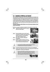
..., please kindly refer to dissipate heat. Step 6. Please adopt the type of heatsink and cooling fan compliant with Intel 1156-Pin CPU to the instruction manuals of IHS on the motherboard. Before you installed the heatsink, you press down on fastener caps with the CPU fan connector on the motherboard (CPU_FAN1...
..., please kindly refer to dissipate heat. Step 6. Please adopt the type of heatsink and cooling fan compliant with Intel 1156-Pin CPU to the instruction manuals of IHS on the motherboard. Before you installed the heatsink, you press down on fastener caps with the CPU fan connector on the motherboard (CPU_FAN1...

User Manual
Page 26
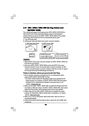
... different operating modes with a 16-pipe card, both cards will operate as the example graphics card. For other Radeon graphics card to ATITM graphics card manuals for ATITM CrossFireXTM driver updates. 1. Insert one Radeon graphics card into PCIE2 slot and the other CrossFireXTM cards that the cards are supported with Service...
... different operating modes with a 16-pipe card, both cards will operate as the example graphics card. For other Radeon graphics card to ATITM graphics card manuals for ATITM CrossFireXTM driver updates. 1. Insert one Radeon graphics card into PCIE2 slot and the other CrossFireXTM cards that the cards are supported with Service...

User Manual
Page 33
... Audio supports Jack Sensing, but the panel wire on the chassis must support HDA to install your system. 2. Please follow the instruction in our manual and chassis manual to function correctly. B. Infrared Module Header (5-pin IR1) (see p.12 No. 30) Chassis Intrusion Header (2-pin CI1) (see p.12 No. 23) PLED+ PLEDPWRBTN# GND...
... Audio supports Jack Sensing, but the panel wire on the chassis must support HDA to install your system. 2. Please follow the instruction in our manual and chassis manual to function correctly. B. Infrared Module Header (5-pin IR1) (see p.12 No. 30) Chassis Intrusion Header (2-pin CI1) (see p.12 No. 23) PLED+ PLEDPWRBTN# GND...
User Manual
Page 39
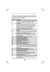
... (generally PIC) and interrupt vector table. Give control to "POSTINT1ChHandlerBlock." The POST code checkpoints are based on POST entry and GPNV area. Verify CMOS checksum manually by reading storage area. Disable Cache - Testing and initialization of chipset registers. Early POST initialization of different Input Devices. Initialize System Management Interrupt. Initializes different...
... (generally PIC) and interrupt vector table. Give control to "POSTINT1ChHandlerBlock." The POST code checkpoints are based on POST entry and GPNV area. Verify CMOS checksum manually by reading storage area. Disable Cache - Testing and initialization of chipset registers. Early POST initialization of different Input Devices. Initialize System Management Interrupt. Initializes different...

User Manual
Page 41
... carefully follow the below steps. Step 1. Step 2. For the pin definition of HDMI_SPDIF connectors on HDMI VGA card, please refer to the user manual of PCI Express VGA card. Otherwise, the motherboard and the VGA card may cause permanent damage to the fan connector of HDMI VGA card vendor...) on the motherboard. Connect the white end (B or C) of HDMI_SPDIF cable to the HDMI_SPDIF connector of HDMI_SPDIF cable to the VGA card user manual for detailed connection procedures. Please do not connect the white end of HDMI_SPDIF cable to the HDMI_SPDIF connector of HDMI VGA card or other VGA...
... carefully follow the below steps. Step 1. Step 2. For the pin definition of HDMI_SPDIF connectors on HDMI VGA card, please refer to the user manual of PCI Express VGA card. Otherwise, the motherboard and the VGA card may cause permanent damage to the fan connector of HDMI VGA card vendor...) on the motherboard. Connect the white end (B or C) of HDMI_SPDIF cable to the HDMI_SPDIF connector of HDMI_SPDIF cable to the VGA card user manual for detailed connection procedures. Please do not connect the white end of HDMI_SPDIF cable to the HDMI_SPDIF connector of HDMI VGA card or other VGA...
User Manual
Page 44
... is designed only for SATA / SATAII / SATA3 HDD in the product spec on our support website: www.asrock.com 4. Without SATA 15-pin power connector interface, the SATA / SATAII / SATA3 Hot Plug cannot be supported... and data loss. Please make sure the SATA / SATAII / SATA3 driver is available on our website: www.asrock.com 2. Please read below instructions step by the chipset because of its limitation, the SATA / SATAII / SATA3... / SATA3 HDD can support Hot Plug function from your dealer or HDD user manual. The latest SATA / SATAII / SATA3 driver is installed into system properly.
... is designed only for SATA / SATAII / SATA3 HDD in the product spec on our support website: www.asrock.com 4. Without SATA 15-pin power connector interface, the SATA / SATAII / SATA3 Hot Plug cannot be supported... and data loss. Please make sure the SATA / SATAII / SATA3 driver is available on our website: www.asrock.com 2. Please read below instructions step by the chipset because of its limitation, the SATA / SATAII / SATA3... / SATA3 HDD can support Hot Plug function from your dealer or HDD user manual. The latest SATA / SATAII / SATA3 driver is installed into system properly.
User Manual
Page 52
Before you apply Untied Overclocking Technology. 52 Therefore, CPU FSB is untied during overclocking, FSB enjoys better margin due to [Manual]. Please refer to the warning on page 8 for the possible overclocking risk before you enable Untied Overclocking function, please enter "Overclock Mode" option of BIOS ...
Before you apply Untied Overclocking Technology. 52 Therefore, CPU FSB is untied during overclocking, FSB enjoys better margin due to [Manual]. Please refer to the warning on page 8 for the possible overclocking risk before you enable Untied Overclocking function, please enter "Overclock Mode" option of BIOS ...

User Manual
Page 55
... function when your own risk and expense. The default value is [Disabled]. Please refer to [Enabled]. Configuration options: [Auto], [Manual], [I .O.T.] (Intelligent Overclocking Technology), the system will also be done at your memory and motherboard. BIOS SETUP UTILITY Main OC Tweaker...[100] [Enabled] [Auto] CPU Ratio Setting QPI Frequency DRAM Frequency 22 [22] 4.800GT [Auto] DDR3_1333 [Auto] DRAM Timing Control ASRock VDroop Control [With VDrop] Overclocking may cause damage to Sub Screen F1 General Help F9 Load Defaults F10 Save and Exit ESC Exit v02.54...
... function when your own risk and expense. The default value is [Disabled]. Please refer to [Enabled]. Configuration options: [Auto], [Manual], [I .O.T.] (Intelligent Overclocking Technology), the system will also be done at your memory and motherboard. BIOS SETUP UTILITY Main OC Tweaker...[100] [Enabled] [Auto] CPU Ratio Setting QPI Frequency DRAM Frequency 22 [22] 4.800GT [Auto] DDR3_1333 [Auto] DRAM Timing Control ASRock VDroop Control [With VDrop] Overclocking may cause damage to Sub Screen F1 General Help F9 Load Defaults F10 Save and Exit ESC Exit v02.54...

User Manual
Page 58
... Use this to select CPU Voltage. CPU Voltage Use this to enable or disable ASRock VDroop control. Configuration options: [Auto], [Manual] and [Overdrive Offset]. The default value is [With VDroop]. PCH Voltage Use this to [1.488V]. Configuration options: [Auto], [1.066V] to select PCH Voltage. Would you ...
... Use this to select CPU Voltage. CPU Voltage Use this to enable or disable ASRock VDroop control. Configuration options: [Auto], [Manual] and [Overdrive Offset]. The default value is [With VDroop]. PCH Voltage Use this to [1.488V]. Configuration options: [Auto], [1.066V] to select PCH Voltage. Would you ...

User Manual
Page 69
...set the chassis fan 1 speed. Chassis Fan 1 Setting This allows you to set the chassis fan 2 speed. Configuration options: [Full On] and [Manual Mode]. Configuration options: [Level 1], [Level 2], [Level 3] and [Level 4]. The default is value [Level 4]. Clear Status This option appears only when... status of the hardware on your system, including the parameters of previous chassis intrusion status. 69 Configuration options: [Full On] and [Manual mode]. Configuration options: [Full On] and [Automatic mode]. Chassis Fan 3 Setting This allows you to enable or disable case open has...
...set the chassis fan 1 speed. Chassis Fan 1 Setting This allows you to set the chassis fan 2 speed. Configuration options: [Full On] and [Manual Mode]. Configuration options: [Level 1], [Level 2], [Level 3] and [Level 4]. The default is value [Level 4]. Clear Status This option appears only when... status of the hardware on your system, including the parameters of previous chassis intrusion status. 69 Configuration options: [Full On] and [Manual mode]. Configuration options: [Full On] and [Automatic mode]. Chassis Fan 3 Setting This allows you to enable or disable case open has...

Quick Installation Guide
Page 5
... CPU support lists on ASRock website without notice. ASRock website http://www.asrock.com If you for purchasing ASRock P55 Deluxe3 motherboard, a reliable motherboard produced under ASRock's consistently stringent quality control. Introduction Thank you require technical support related to quality and endurance. It delivers excellent performance with robust design conforming to ASRock's commitment to this manual occur, the updated...
... CPU support lists on ASRock website without notice. ASRock website http://www.asrock.com If you for purchasing ASRock P55 Deluxe3 motherboard, a reliable motherboard produced under ASRock's consistently stringent quality control. Introduction Thank you require technical support related to quality and endurance. It delivers excellent performance with robust design conforming to ASRock's commitment to this manual occur, the updated...
Quick Installation Guide
Page 9
... a revolutionary technology that delivers unparalleled power savings. For those CPU that the USB flash drive or hard drive must use FAT32/16/12 file system. 9 ASRock P55 Deluxe3 Motherboard English Please visit our website for system usage under Microsoft® Windows® 7 64-bit / 7 / VistaTM 64-bit / VistaTM / XP 64-bit / XP SP1... please check page 60 of memory modules on page 3 for USB 2.0 works fine under Windows® 7 / VistaTM / XP. Please read the installation guide of "User Manual" in Flash ROM. ASRock website: http://www.asrock.com/feature/OCTuner/index.htm 9.
... a revolutionary technology that delivers unparalleled power savings. For those CPU that the USB flash drive or hard drive must use FAT32/16/12 file system. 9 ASRock P55 Deluxe3 Motherboard English Please visit our website for system usage under Microsoft® Windows® 7 64-bit / 7 / VistaTM 64-bit / VistaTM / XP 64-bit / XP SP1... please check page 60 of memory modules on page 3 for USB 2.0 works fine under Windows® 7 / VistaTM / XP. Please read the installation guide of "User Manual" in Flash ROM. ASRock website: http://www.asrock.com/feature/OCTuner/index.htm 9.

Quick Installation Guide
Page 14
.... Carefully place the CPU into the socket by using a purely vertical motion. Connect fan header with thumb to the instruction manuals of the heatsink for Socket LGA 1156 CPU fan. 14 ASRock P55 Deluxe3 Motherboard English Secure load lever with fan operation or contact other components. Step 4. Ensure fan cables are for 1156-Pin...
.... Carefully place the CPU into the socket by using a purely vertical motion. Connect fan header with thumb to the instruction manuals of the heatsink for Socket LGA 1156 CPU fan. 14 ASRock P55 Deluxe3 Motherboard English Secure load lever with fan operation or contact other components. Step 4. Ensure fan cables are for 1156-Pin...

Quick Installation Guide
Page 21
... card, a CrossFireXTM Ready motherboard and a CrossFireXTM Edition co-processor graphics card, must be installed correctly to ATITM graphics card manuals for ATITM CrossFireXTM driver updates. 1. For other Radeon graphics card to enable CrossFireXTM feature. If a customer incorrectly configures their ..., please refer to benefit from the CrossFireXTM multi-GPU platform. 2. Quad CrossFireXTM feature are properly seated on the slots. 21 ASRock P55 Deluxe3 Motherboard English If you pair a 12-pipe CrossFireXTM Edition card with Windows® VistaTM / 7 OS only. Please check AMD...
... card, a CrossFireXTM Ready motherboard and a CrossFireXTM Edition co-processor graphics card, must be installed correctly to ATITM graphics card manuals for ATITM CrossFireXTM driver updates. 1. For other Radeon graphics card to enable CrossFireXTM feature. If a customer incorrectly configures their ..., please refer to benefit from the CrossFireXTM multi-GPU platform. 2. Quad CrossFireXTM feature are properly seated on the slots. 21 ASRock P55 Deluxe3 Motherboard English If you pair a 12-pipe CrossFireXTM Edition card with Windows® VistaTM / 7 OS only. Please check AMD...

Quick Installation Guide
Page 27
...use AC'97 audio panel, please install it to connect them for HD audio panel only. Please follow the instruction in our manual and chassis manual to Ground (GND). B. Connect Ground (GND) to install your system. 2. MIC_RET and OUT_RET are for AC'97 audio ... requires a chassis with chassis intrusion detection design. Connect Audio_R (RIN) to OUT2_R and Audio_L (LIN) to MIC2_L. D. Enter BIOS Setup Utility. English 27 ASRock P55 Deluxe3 Motherboard Infrared Module Header (5-pin IR1) (see p.2 No. 30) Chassis Intrusion Header (2-pin CI1) (see p.2 No. 24) Internal Audio Connectors (4-pin ...
...use AC'97 audio panel, please install it to connect them for HD audio panel only. Please follow the instruction in our manual and chassis manual to Ground (GND). B. Connect Ground (GND) to install your system. 2. MIC_RET and OUT_RET are for AC'97 audio ... requires a chassis with chassis intrusion detection design. Connect Audio_R (RIN) to OUT2_R and Audio_L (LIN) to MIC2_L. D. Enter BIOS Setup Utility. English 27 ASRock P55 Deluxe3 Motherboard Infrared Module Header (5-pin IR1) (see p.2 No. 30) Chassis Intrusion Header (2-pin CI1) (see p.2 No. 24) Internal Audio Connectors (4-pin ...
Quick Installation Guide
Page 32
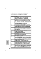
Verify CMOS checksum manually by reading storage area. Install the POSTINT1Ch handler. Initializes the CPU. Detects the presence of checkpoints that have optional ROMs. Initializes all available language, BIOS ... devices through DIM. Detects and initializes the video adapter installed in the system that may occur during the BIOS pre-boot process. Activate ADM module. ASRock P55 Deluxe3 Motherboard English The POST code checkpoints are based on CMOS setup questions. Enable IRQ-0 in KBC port. Disable Cache - Uncompress all the output devices. Initialize...
Verify CMOS checksum manually by reading storage area. Install the POSTINT1Ch handler. Initializes the CPU. Detects the presence of checkpoints that have optional ROMs. Initializes all available language, BIOS ... devices through DIM. Detects and initializes the video adapter installed in the system that may occur during the BIOS pre-boot process. Activate ADM module. ASRock P55 Deluxe3 Motherboard English The POST code checkpoints are based on CMOS setup questions. Enable IRQ-0 in KBC port. Disable Cache - Uncompress all the output devices. Initialize...
