
User Manual
Page 1
P4i45PE+ User Manual Version 1.0 Published November 2003 Copyright©2003 ASRock INC. All rights reserved. 1
P4i45PE+ User Manual Version 1.0 Published November 2003 Copyright©2003 ASRock INC. All rights reserved. 1

User Manual
Page 4
... advanced users' reference, the Appendix appearing on page 24 offers more advanced BIOS setup information. ASRock website http://www.asrock.com 1.1 Package Contents ASRock P4i45PE+ Motherboard (ATX Form Factor: 12.0-in x 7.0-in, 30.5 cm x 17.8 cm) ASRock P4i45PE+ Quick Installation Guide ASRock P4i45PE+ Support CD One 80-conductor Ultra ATA 66/100 IDE Ribbon Cable One Ribbon Cable...
... advanced users' reference, the Appendix appearing on page 24 offers more advanced BIOS setup information. ASRock website http://www.asrock.com 1.1 Package Contents ASRock P4i45PE+ Motherboard (ATX Form Factor: 12.0-in x 7.0-in, 30.5 cm x 17.8 cm) ASRock P4i45PE+ Quick Installation Guide ASRock P4i45PE+ Support CD One 80-conductor Ultra ATA 66/100 IDE Ribbon Cable One Ribbon Cable...

User Manual
Page 7
... TMD7608F8E43B TMD7608F8E50B TTD7608F8E50B DOUBLE SIDE SINGLE SIDE SINGLE SIDE SINGLE SIDE Since the memory types are changing rapidly, please visit ASRock website (http://www.asrock.com/support/index.htm) for P4i45PE+ motherboard. CPU FSB P4i45PE+ 800 MHz Configuration Note 1. Set the "FSB" jumper to support higher CPU front side bus frequencies on DDR1 DIMM...
... TMD7608F8E43B TMD7608F8E50B TTD7608F8E50B DOUBLE SIDE SINGLE SIDE SINGLE SIDE SINGLE SIDE Since the memory types are changing rapidly, please visit ASRock website (http://www.asrock.com/support/index.htm) for P4i45PE+ motherboard. CPU FSB P4i45PE+ 800 MHz Configuration Note 1. Set the "FSB" jumper to support higher CPU front side bus frequencies on DDR1 DIMM...

User Manual
Page 13
... Windows 98 / ME, you MUST install the SATA driver before you intend to use. Otherwise the system will not work properly. 13 The ASRock AGP slot has a special locking mechanism which can securely fasten the graphics card inserted. Remove the system unit cover (if your graphics card, ... may cause permanent damage! Remove the bracket facing the slot that the power supply is switched off or the power cord is completely seated on P4i45PE+ motherboard. Step 5. 2.6 Expansion Slots (PCI and AGP Slots) There are used to install a graphics card. Fasten the card to the chassis...
... Windows 98 / ME, you MUST install the SATA driver before you intend to use. Otherwise the system will not work properly. 13 The ASRock AGP slot has a special locking mechanism which can securely fasten the graphics card inserted. Remove the system unit cover (if your graphics card, ... may cause permanent damage! Remove the bracket facing the slot that the power supply is switched off or the power cord is completely seated on P4i45PE+ motherboard. Step 5. 2.6 Expansion Slots (PCI and AGP Slots) There are used to install a graphics card. Fasten the card to the chassis...

User Manual
Page 1
P4i45PE User Manual Version 1.0 Published May 2003 Copyright©2003 ASRock INC. All rights reserved. 1
P4i45PE User Manual Version 1.0 Published May 2003 Copyright©2003 ASRock INC. All rights reserved. 1

User Manual
Page 4
... system builders. Chapter 1 Introduction Thank you for floppy drive (1 x ribbon cable) 1 ASRock I/O shield 4 Chapter 3 and 4 contain basic BIOS setup and Support CD information. ASRock website http://www.asrock.com 1.1 Package Contents ASRock P4i45PE motherboard (ATX form factor: 12" x 8.6", 30.5 x 21.8 cm) ASRock P4i45PE Quick Installation Guide ASRock Intel-Intel Series Support CD 1 Cable for IDE devices (1 x ATA 66...
... system builders. Chapter 1 Introduction Thank you for floppy drive (1 x ribbon cable) 1 ASRock I/O shield 4 Chapter 3 and 4 contain basic BIOS setup and Support CD information. ASRock website http://www.asrock.com 1.1 Package Contents ASRock P4i45PE motherboard (ATX form factor: 12" x 8.6", 30.5 x 21.8 cm) ASRock P4i45PE Quick Installation Guide ASRock Intel-Intel Series Support CD 1 Cable for IDE devices (1 x ATA 66...

User Manual
Page 13
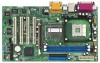
...used to install expansion cards that you intend to use . PCI slots: PCI slots are 5 PCI slots and 1 AGP slot on P4i45PE motherboard! The ASRock AGP slot has a special locking mechanism which can securely fasten the graphics card inserted. Remove the bracket facing the slot that have ... the notch on the DIMM matches the break on the slot. Before installing the expansion card, read the documentation of Memory Modules (DIMM) P4i45PE motherboard provides two 184-pin DDR (Double Data Rate) DIMM slots. Align the card connector with screws. Step 2. Please make necessary hardware...
...used to install expansion cards that you intend to use . PCI slots: PCI slots are 5 PCI slots and 1 AGP slot on P4i45PE motherboard! The ASRock AGP slot has a special locking mechanism which can securely fasten the graphics card inserted. Remove the bracket facing the slot that have ... the notch on the DIMM matches the break on the slot. Before installing the expansion card, read the documentation of Memory Modules (DIMM) P4i45PE motherboard provides two 184-pin DDR (Double Data Rate) DIMM slots. Align the card connector with screws. Step 2. Please make necessary hardware...

User Manual
Page 15
...10) Pin1 FLOPPY1 Red marking Note: Match the red marking on the floppy ribbon cable with Pin1. If the default USB ports on P4i45PE motherboard provides you to the secondary IDE connector (IDE2, black). 2.8 Connectors Connectors are not sufficient, this BLACK end to the IDE devices... USB_PWR P-5 P+5 GND DUMMY 1 GND P+4 P-4 USB_PWR IRTX +5V DUMMY 1 GND IRRX AUX-R GND GND AUX1 AUX-L CD-R GND GND CD1 CD-L ASRock I/OTM on the rear panel are NOT jumpers. This connector supports an optional wireless transmitting and receiving infrared module. DO NOT place jumper caps over...
...10) Pin1 FLOPPY1 Red marking Note: Match the red marking on the floppy ribbon cable with Pin1. If the default USB ports on P4i45PE motherboard provides you to the secondary IDE connector (IDE2, black). 2.8 Connectors Connectors are not sufficient, this BLACK end to the IDE devices... USB_PWR P-5 P+5 GND DUMMY 1 GND P+4 P-4 USB_PWR IRTX +5V DUMMY 1 GND IRRX AUX-R GND GND AUX1 AUX-L CD-R GND GND CD1 CD-L ASRock I/OTM on the rear panel are NOT jumpers. This connector supports an optional wireless transmitting and receiving infrared module. DO NOT place jumper caps over...


