
User Manual
Page 6
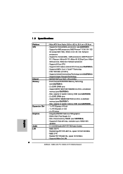
... un-buffered memory (see CAUTION 7) - Max. Support DDR2 1066/800/667/533 non-ECC, un-buffered memory (see CAUTION 5) - N68C-GS FX Realtek Giga PHY RTL8211CL, speed 10/100/1000 Mb/s - Support for Socket AM3+ processors (see CAUTION 1) - NVIDIA® GeForce 7025... VT1705 Audio Codec) - Micro ATX Form Factor: 9.6-in x 8.2-in, 24.4 cm x 20.8 cm - Max. Supports 8-Core CPU - Max. Dual Channel DDR3/DDR2 Memory Technology (see CAUTION 8) - Supports D-Sub with max. 1.2 Specifications Platform CPU Chipset Memory Expansion Slot Graphics Audio LAN - FSB 1000 MHz ...
... un-buffered memory (see CAUTION 7) - Max. Support DDR2 1066/800/667/533 non-ECC, un-buffered memory (see CAUTION 5) - N68C-GS FX Realtek Giga PHY RTL8211CL, speed 10/100/1000 Mb/s - Support for Socket AM3+ processors (see CAUTION 1) - NVIDIA® GeForce 7025... VT1705 Audio Codec) - Micro ATX Form Factor: 9.6-in x 8.2-in, 24.4 cm x 20.8 cm - Max. Supports 8-Core CPU - Max. Dual Channel DDR3/DDR2 Memory Technology (see CAUTION 8) - Supports D-Sub with max. 1.2 Specifications Platform CPU Chipset Memory Expansion Slot Graphics Audio LAN - FSB 1000 MHz ...

User Manual
Page 9
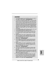
... SATAII hard disk drive to enjoy an instant performance boost. When UCC feature is supported with a better price. This motherboard supports Dual Channel Memory Technology. If you want to adopt DDR3 1600 memory module on this motherboard, please refer to change. For Windows® OS ... disk to adjust your system by the chipset vendor and is no such limitation. 7. ASRock website http://www.asrock.com 6. As long as a simple switch of the BIOS option "ASrock UCC", you implement Dual Channel Memory Technology, make sure to read "Untied Overclocking Technology" on page 26 to SATAII...
... SATAII hard disk drive to enjoy an instant performance boost. When UCC feature is supported with a better price. This motherboard supports Dual Channel Memory Technology. If you want to adopt DDR3 1600 memory module on this motherboard, please refer to change. For Windows® OS ... disk to adjust your system by the chipset vendor and is no such limitation. 7. ASRock website http://www.asrock.com 6. As long as a simple switch of the BIOS option "ASrock UCC", you implement Dual Channel Memory Technology, make sure to read "Untied Overclocking Technology" on page 26 to SATAII...
User Manual
Page 12
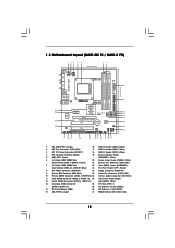
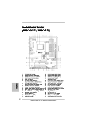
... 21 Chassis Fan Connector (CHA_FAN1) 7 2 x 240-pin DDR3 DIMM Slots 22 Clear CMOS Jumper (CLRCMOS1) (Dual Channel: DDR3_A1, DDR3_B1; 1.3 Motherboard Layout (N68C-GS FX / N68C-S FX) Designed in Taipei DDRII_1 (64 bit, 240-piFnSmBod8ul0e)0 DDR3_A1 (64 bit, 240-pin module) DDRII_2 (64 bit, ... Chassis Speaker Header 5 AMD CPU Socket (SPEAKER 1, White) 6 2 x 240-pin DDR2 DIMM Slots 20 System Panel Header (PANEL1, White) (Dual Channel: DDRII_1, DDRII_2; Blue) 23 Print Port Header (LPT1, Purple) 8 ATX Power Connector (ATXPWR1) 24 Floppy Connector (FLOPPY1) 9 Primary IDE Connector (IDE1...
... 21 Chassis Fan Connector (CHA_FAN1) 7 2 x 240-pin DDR3 DIMM Slots 22 Clear CMOS Jumper (CLRCMOS1) (Dual Channel: DDR3_A1, DDR3_B1; 1.3 Motherboard Layout (N68C-GS FX / N68C-S FX) Designed in Taipei DDRII_1 (64 bit, 240-piFnSmBod8ul0e)0 DDR3_A1 (64 bit, 240-pin module) DDRII_2 (64 bit, ... Chassis Speaker Header 5 AMD CPU Socket (SPEAKER 1, White) 6 2 x 240-pin DDR2 DIMM Slots 20 System Panel Header (PANEL1, White) (Dual Channel: DDRII_1, DDRII_2; Blue) 23 Print Port Header (LPT1, Purple) 8 ATX Power Connector (ATXPWR1) 24 Floppy Connector (FLOPPY1) 9 Primary IDE Connector (IDE1...
User Manual
Page 13
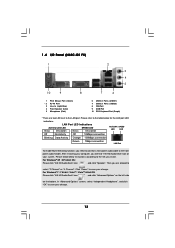
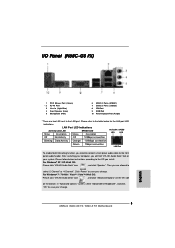
... refer to the table below instructions according to the OS you need to connect a front panel audio cable to the front panel audio header. 1 . 4 I/O Panel (N68C-GS FX) 1 2 3 4 5 10 9 8 7 6 1 PS/2 Mouse Port (Green) * 2 RJ-45 Port 3 Line In (Light Blue) 4 Front Speaker (Lime) 5 Microphone (Pink) 6 USB 2.0 Ports (USB01) 7 USB 2.0 Ports (USB23) 8 VGA Port...
... refer to the table below instructions according to the OS you need to connect a front panel audio cable to the front panel audio header. 1 . 4 I/O Panel (N68C-GS FX) 1 2 3 4 5 10 9 8 7 6 1 PS/2 Mouse Port (Green) * 2 RJ-45 Port 3 Line In (Light Blue) 4 Front Speaker (Lime) 5 Microphone (Pink) 6 USB 2.0 Ports (USB01) 7 USB 2.0 Ports (USB23) 8 VGA Port...

User Manual
Page 14
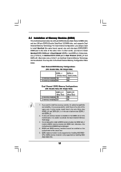
..." on the left side on your computer, you need to connect a front panel audio cable to select "2 Channel" or "4 Channel". LAN Port LED Indications Activity/Link LED SPEED LED Status Description Status Description ACT/LINK SPEED LED LED Off No... Deck" icon , and click "Speaker". Click "Power" to the table below instructions according to save your change . Please refer to save your change . 14 1 . 5 I/O Panel (N68C-S FX) 1 2 3 4 5 10 9 8 7 6 1 PS/2 Mouse Port (Green) * 2 RJ-45 Port 3 Line In (Light Blue) 4 Front Speaker (Lime) 5 Microphone (Pink) 6 ...
..." on the left side on your computer, you need to connect a front panel audio cable to select "2 Channel" or "4 Channel". LAN Port LED Indications Activity/Link LED SPEED LED Status Description Status Description ACT/LINK SPEED LED LED Off No... Deck" icon , and click "Speaker". Click "Power" to the table below instructions according to save your change . Please refer to save your change . 14 1 . 5 I/O Panel (N68C-S FX) 1 2 3 4 5 10 9 8 7 6 1 PS/2 Mouse Port (Green) * 2 RJ-45 Port 3 Line In (Light Blue) 4 Front Speaker (Lime) 5 Microphone (Pink) 6 ...
User Manual
Page 17
...to install a DDR3 memory module into DDR2 slot or install a DDR2 memory module into DDR3 slot; In other words, install them in Dual Channel (DDRII_1 and DDRII_2; DDR2 and DDR3 memory modules cannot be damaged. 4. Yellow slots; You may be installed on this motherboard, it is unable...p.12 No.6), or identical DDR3 DIMM pair in the slots of yellow slots (DDRII_1 and DDRII_2). 2. If you have to activate the Dual Channel Memory Technology. 3. In other words, you want to install two memory modules, for optimal compatibility and reliability, it is recommended to install them ...
...to install a DDR3 memory module into DDR2 slot or install a DDR2 memory module into DDR3 slot; In other words, install them in Dual Channel (DDRII_1 and DDRII_2; DDR2 and DDR3 memory modules cannot be damaged. 4. Yellow slots; You may be installed on this motherboard, it is unable...p.12 No.6), or identical DDR3 DIMM pair in the slots of yellow slots (DDRII_1 and DDRII_2). 2. If you have to activate the Dual Channel Memory Technology. 3. In other words, you want to install two memory modules, for optimal compatibility and reliability, it is recommended to install them ...

User Manual
Page 34
.../15/2011] BIOS Version : N68C-GS FX P1.00 Processor Type : AMD Phenom (tm) II X4 910e Processor (64bit) Processor Speed : 2600MHz Microcode Update : 100F43/10000B6 L1 Cache Size : 512KB L2 Cache Size : 2048KB L3 Cache Size : 6144KB Total Memory DDR3_A1 DDR3_B1 : 4096MB with 256MB shared memory Single-Channel Memory Mode : 4096MB/533MHz DDR3_1066...
.../15/2011] BIOS Version : N68C-GS FX P1.00 Processor Type : AMD Phenom (tm) II X4 910e Processor (64bit) Processor Speed : 2600MHz Microcode Update : 100F43/10000B6 L1 Cache Size : 512KB L2 Cache Size : 2048KB L3 Cache Size : 6144KB Total Memory DDR3_A1 DDR3_B1 : 4096MB with 256MB shared memory Single-Channel Memory Mode : 4096MB/533MHz DDR3_1066...

User Manual
Page 35
... Overview System Time System Date [17:00:09] [Thu 12/15/2011] BIOS Version : N68C-S FX P1.00 Processor Type : AMD Phenom (tm) II X4 910e Processor (64bit) Processor Speed ... : 2048KB L3 Cache Size : 6144KB Total Memory DDR3_A1 DDR3_B1 : 4096MB with 256MB shared memory Single-Channel Memory Mode : 4096MB/533MHz DDR3_1066 : None Use [Enter], [TAB] or [SHIFT-TAB] to...Frequency (MHz) Boot Failure Guard Boot Failure Guard Count CPU/LDT Spread Spectrum PCIE Spread Spectrum SATA Spread Spectrum ASRock UCC AMD Turbo Core Technology AMD IO C-State Support CPU Active Core Control [Auto] [200] [100] ...
... Overview System Time System Date [17:00:09] [Thu 12/15/2011] BIOS Version : N68C-S FX P1.00 Processor Type : AMD Phenom (tm) II X4 910e Processor (64bit) Processor Speed ... : 2048KB L3 Cache Size : 6144KB Total Memory DDR3_A1 DDR3_B1 : 4096MB with 256MB shared memory Single-Channel Memory Mode : 4096MB/533MHz DDR3_1066 : None Use [Enter], [TAB] or [SHIFT-TAB] to...Frequency (MHz) Boot Failure Guard Boot Failure Guard Count CPU/LDT Spread Spectrum PCIE Spread Spectrum SATA Spread Spectrum ASRock UCC AMD Turbo Core Technology AMD IO C-State Support CPU Active Core Control [Auto] [200] [100] ...

User Manual
Page 38
...value is [Auto]. The default is [Auto]. Power Down Enable Use this item to adjust the memory controller mode. Channel Interleaving It allows you to change Command Rate Auto/Manual setting. The default value is [Hash 2]. Command Rate Use this item... is [Hash 1]. The default value is [Auto]. 38 Memory Timing BIOS SETUP UTILITY OC Tweaker Memory Timing Memory Controller Mode Power Down Enable Bank Interleaving Channel Interleaving CAS Latency (CL) 7 TRCD 7 TRP 7 TRAS 20 Command Rate 2 TRC 27 TWR 8 TRFC 110 TRRD 4 TWTR 4 TRTP 4 TFAW 16 [...
...value is [Auto]. The default is [Auto]. Power Down Enable Use this item to adjust the memory controller mode. Channel Interleaving It allows you to change Command Rate Auto/Manual setting. The default value is [Hash 2]. Command Rate Use this item... is [Hash 1]. The default value is [Auto]. 38 Memory Timing BIOS SETUP UTILITY OC Tweaker Memory Timing Memory Controller Mode Power Down Enable Bank Interleaving Channel Interleaving CAS Latency (CL) 7 TRCD 7 TRP 7 TRAS 20 Command Rate 2 TRC 27 TWR 8 TRFC 110 TRRD 4 TWTR 4 TRTP 4 TFAW 16 [...

User Manual
Page 47
... BIOS SETUP UTILITY Advanced Configure Super IO Chipset OnBoard Floppy Controller Serial Port Address Parallel Port Address Parallel Port Mode EPP Version ECP Mode DMA Channel Parallel Port IRQ [Enabled] [3F8 / IRQ4] [378] [ECP + EPP] [1.9] [DMA3] [IRQ7] Allow BIOS to Enable or Disable Floppy Controller. +F1 F9 F10 ESC Select Screen...
... BIOS SETUP UTILITY Advanced Configure Super IO Chipset OnBoard Floppy Controller Serial Port Address Parallel Port Address Parallel Port Mode EPP Version ECP Mode DMA Channel Parallel Port IRQ [Enabled] [3F8 / IRQ4] [378] [ECP + EPP] [1.9] [DMA3] [IRQ7] Allow BIOS to Enable or Disable Floppy Controller. +F1 F9 F10 ESC Select Screen...

User Manual
Page 48
...], [Bi-Directional], and [ECP+EPP]. EPP Version Use this option is [ECP+EPP]. If this item to set the ECP mode DMA channel. Configuration options: [1.9] and [1.7]. ECP Mode DMA Channel Use this item to [ECP+EPP], it will show the EPP version in the following item, "EPP Version". The default value is...
...], [Bi-Directional], and [ECP+EPP]. EPP Version Use this option is [ECP+EPP]. If this item to set the ECP mode DMA channel. Configuration options: [1.9] and [1.7]. ECP Mode DMA Channel Use this item to [ECP+EPP], it will show the EPP version in the following item, "EPP Version". The default value is...
Quick Installation Guide
Page 2
...PCI Express x1 Slot (PCIE1) 15 USB_PWR2 Jumper 31 NVIDIA GeForce 7025 / nForce 630a 2 ASRock N68C-GS FX / N68C-S FX Motherboard Yellow) 21 Chassis Fan Connector (CHA_FAN1) 7 2 x 240-pin DDR3 DIMM Slots 22 Clear CMOS Jumper (CLRCMOS1) (Dual Channel: DDR3_A1, DDR3_B1; Motherboard Layout (N68C-GS FX / N68C-S FX) English 1 PS2_USB_PWR1 Jumper 16 USB 2.0 Header (USB8_9, Blue) 2 CPU Fan Connector (... Retention Module 19 Chassis Speaker Header 5 AMD CPU Socket (SPEAKER 1, White) 6 2 x 240-pin DDR2 DIMM Slots 20 System Panel Header (PANEL1, White) (Dual Channel: DDRII_1, DDRII_2;
...PCI Express x1 Slot (PCIE1) 15 USB_PWR2 Jumper 31 NVIDIA GeForce 7025 / nForce 630a 2 ASRock N68C-GS FX / N68C-S FX Motherboard Yellow) 21 Chassis Fan Connector (CHA_FAN1) 7 2 x 240-pin DDR3 DIMM Slots 22 Clear CMOS Jumper (CLRCMOS1) (Dual Channel: DDR3_A1, DDR3_B1; Motherboard Layout (N68C-GS FX / N68C-S FX) English 1 PS2_USB_PWR1 Jumper 16 USB 2.0 Header (USB8_9, Blue) 2 CPU Fan Connector (... Retention Module 19 Chassis Speaker Header 5 AMD CPU Socket (SPEAKER 1, White) 6 2 x 240-pin DDR2 DIMM Slots 20 System Panel Header (PANEL1, White) (Dual Channel: DDRII_1, DDRII_2;
Quick Installation Guide
Page 3
I/O Panel (N68C-GS FX) 1 PS/2 Mouse Port (Green) * 2 RJ-45 Port 3 Line In (Light Blue) 4 Front Speaker (Lime) 5 Microphone (Pink) 6 USB 2.0 Ports (USB01) 7 USB 2.0 Ports (USB23) 8 VGA Port 9 COM Port 10 PS/2 Keyboard Port (Purple) * There are allowed to select "2 Channel" or "4 Channel". LAN Port ...and click "OK" to the front panel audio header. Please refer to the table below instructions according to save your change . 3 ASRock N68C-GS FX / N68C-S FX Motherboard English Please follow below for the LAN port LED indications. Click "Power" to the OS you will find "VIA HD Audio...
I/O Panel (N68C-GS FX) 1 PS/2 Mouse Port (Green) * 2 RJ-45 Port 3 Line In (Light Blue) 4 Front Speaker (Lime) 5 Microphone (Pink) 6 USB 2.0 Ports (USB01) 7 USB 2.0 Ports (USB23) 8 VGA Port 9 COM Port 10 PS/2 Keyboard Port (Purple) * There are allowed to select "2 Channel" or "4 Channel". LAN Port ...and click "OK" to the front panel audio header. Please refer to the table below instructions according to save your change . 3 ASRock N68C-GS FX / N68C-S FX Motherboard English Please follow below for the LAN port LED indications. Click "Power" to the OS you will find "VIA HD Audio...

Quick Installation Guide
Page 4
... In "Advanced Options" screen, select "Independent Headphone", and click "OK" to save your system. Please follow below for the LAN port LED indications. I/O Panel (N68C-S FX) 1 PS/2 Mouse Port (Green) * 2 RJ-45 Port 3 Line In (Light Blue) 4 Front Speaker (Lime) 5 Microphone (Pink) 6 USB 2.0 Ports...Channel" or "4 Channel". Then you will find "VIA HD Audio Deck" tool on the bottom. For Windows® 7 / 7 64-bit / VistaTM / VistaTM 64-bit OS: Please click "VIA HD Audio Deck" icon , and click "Advanced Options" on the left side on your change . 4 ASRock N68C-GS FX / N68C-S FX...
... In "Advanced Options" screen, select "Independent Headphone", and click "OK" to save your system. Please follow below for the LAN port LED indications. I/O Panel (N68C-S FX) 1 PS/2 Mouse Port (Green) * 2 RJ-45 Port 3 Line In (Light Blue) 4 Front Speaker (Lime) 5 Microphone (Pink) 6 USB 2.0 Ports...Channel" or "4 Channel". Then you will find "VIA HD Audio Deck" tool on the bottom. For Windows® 7 / 7 64-bit / VistaTM / VistaTM 64-bit OS: Please click "VIA HD Audio Deck" icon , and click "Advanced Options" on the left side on your change . 4 ASRock N68C-GS FX / N68C-S FX...
Quick Installation Guide
Page 6
...Express x1 slot - 2 x PCI slots - resolution up to 1920x1440 @ 60Hz - 5.1 CH HD Audio (VIA® VT1705 Audio Codec) - N68C-GS FX Realtek Giga PHY RTL8211CL, speed 10/100/1000 Mb/s - capacity of system memory: 8GB (see CAUTION 6) - 2 x DDR2 DIMM slots - ...Hyper-Transport Technology - Dual Channel DDR3/DDR2 Memory Technology (see CAUTION 8) - Max. Max. Max. shared memory 256MB (see CAUTION 4) - 2 x DDR3 DIMM slots - Supports D-Sub with max. N68C-S FX Realtek PHY RTL8201EL, speed 10/100 Mb/s - Supports Wake-On-LAN 6 ASRock N68C-GS FX / N68C-S FX Motherboard English
...Express x1 slot - 2 x PCI slots - resolution up to 1920x1440 @ 60Hz - 5.1 CH HD Audio (VIA® VT1705 Audio Codec) - N68C-GS FX Realtek Giga PHY RTL8211CL, speed 10/100/1000 Mb/s - capacity of system memory: 8GB (see CAUTION 6) - 2 x DDR2 DIMM slots - ...Hyper-Transport Technology - Dual Channel DDR3/DDR2 Memory Technology (see CAUTION 8) - Max. Max. Max. shared memory 256MB (see CAUTION 4) - 2 x DDR3 DIMM slots - Supports D-Sub with max. N68C-S FX Realtek PHY RTL8201EL, speed 10/100 Mb/s - Supports Wake-On-LAN 6 ASRock N68C-GS FX / N68C-S FX Motherboard English
Quick Installation Guide
Page 9
...CPU up to change. Before you adopt. Please check NVIDIA® website for system usage under Windows® environment. ASRock website: http://www.asrock.com 9 ASRock N68C-GS FX / N68C-S FX Motherboard English This motherboard supports Untied Overclocking Technology. Please read the "SATAII Hard Disk Setup Guide" on page 26 ... 9. Please refer to 95W. If you want to adopt DDR2 1066 memory module on the AM2+ / AM3 CPU you implement Dual Channel Memory Technology, make sure to read the installation guide of "User Manual" in addition, not every AM2+ / AM3 / AM3+ CPU...
...CPU up to change. Before you adopt. Please check NVIDIA® website for system usage under Windows® environment. ASRock website: http://www.asrock.com 9 ASRock N68C-GS FX / N68C-S FX Motherboard English This motherboard supports Untied Overclocking Technology. Please read the "SATAII Hard Disk Setup Guide" on page 26 ... 9. Please refer to 95W. If you want to adopt DDR2 1066 memory module on the AM2+ / AM3 CPU you implement Dual Channel Memory Technology, make sure to read the installation guide of "User Manual" in addition, not every AM2+ / AM3 / AM3+ CPU...

Quick Installation Guide
Page 14
... pair in the slots of the same color. DDR2 memory module is only supported by installing AM2/ AM2+/AM3 CPU. 14 ASRock N68C-GS FX / N68C-S FX Motherboard English If you have to the Dual Channel Memory Configuration Table below. DDR2 and DDR3 memory modules cannot be damaged. 4. 2.3 Installation of yellow slots (DDRII_1 and DDRII_2). 2. In other...
... pair in the slots of the same color. DDR2 memory module is only supported by installing AM2/ AM2+/AM3 CPU. 14 ASRock N68C-GS FX / N68C-S FX Motherboard English If you have to the Dual Channel Memory Configuration Table below. DDR2 and DDR3 memory modules cannot be damaged. 4. 2.3 Installation of yellow slots (DDRII_1 and DDRII_2). 2. In other...

RAID Installation Guide
Page 10
...changes of the Free Disks and Array Disks lists. M 1: Channel - Healthy NVIDIA STRIPING 74.53G 10 The adapter / channel / master / slave status of each channel has a slave and a master. M Channel 1, controller 0, Master 1 . 1 . For example: 1 . 0 . M Channel 1, controller 1, Master Finally, the Array List window appears, ... used, the system can review the RAID arrays that you can have set up. Typically, channel 0 is used for Parallel ATA drives while channel 1 is usually one or more channels. In a typical system there is used for Serial ATA drives. 0: Controller M: M means...
...changes of the Free Disks and Array Disks lists. M 1: Channel - Healthy NVIDIA STRIPING 74.53G 10 The adapter / channel / master / slave status of each channel has a slave and a master. M Channel 1, controller 0, Master 1 . 1 . For example: 1 . 0 . M Channel 1, controller 1, Master Finally, the Array List window appears, ... used, the system can review the RAID arrays that you can have set up. Typically, channel 0 is used for Parallel ATA drives while channel 1 is usually one or more channels. In a typical system there is used for Serial ATA drives. 0: Controller M: M means...
