RAID Installation Guide
Page 2
... cause data damage or data loss. WARNING!! Although RAID 0 function can start to use RAID 0, RAID 1, or JBOD function with your motherboard provides in advance and follow the instruction in our support CD or "Quick Installation Guide", you can improve the access performance, it does not... you may choose to use NVIDIA RAID Utility to read and write data in the other drive if one drive fails. 2 If your motherboard. 1. NVIDIA BIOS RAID Installation Guide NVIDIA BIOS RAID Installation Guide is called data mirroring that optimizes two identical hard disk drives to configure ...
... cause data damage or data loss. WARNING!! Although RAID 0 function can start to use RAID 0, RAID 1, or JBOD function with your motherboard provides in advance and follow the instruction in our support CD or "Quick Installation Guide", you can improve the access performance, it does not... you may choose to use NVIDIA RAID Utility to read and write data in the other drive if one drive fails. 2 If your motherboard. 1. NVIDIA BIOS RAID Installation Guide NVIDIA BIOS RAID Installation Guide is called data mirroring that optimizes two identical hard disk drives to configure ...
RAID Installation Guide
Page 12
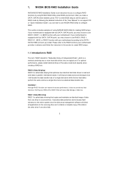
...NVRAIDMAN to below : - Please refer to create RAID 0 (Striping). RAID 0: Striping - RAID 0+1: Stripe Mirroring - If your motherboard is different from NVIDIA utility naming. B. Creating RAID Arrays This section includes examples of using NVRAIDMAN for detailed information. JBOD: Spanning -... be mentioned in this section to create other RAID arrays, 12 RAID 5 NOTE: Under Windows XP OS, the connector naming on our motherboard is equipped with two SATA / SATAII ports, you install. SATAII_1 (port 1.0) --> Means controller 1's first port SATAII_2 (port 1.1) -->...
...NVRAIDMAN to below : - Please refer to create RAID 0 (Striping). RAID 0: Striping - RAID 0+1: Stripe Mirroring - If your motherboard is different from NVIDIA utility naming. B. Creating RAID Arrays This section includes examples of using NVRAIDMAN for detailed information. JBOD: Spanning -... be mentioned in this section to create other RAID arrays, 12 RAID 5 NOTE: Under Windows XP OS, the connector naming on our motherboard is equipped with two SATA / SATAII ports, you install. SATAII_1 (port 1.0) --> Means controller 1's first port SATAII_2 (port 1.1) -->...

User Manual
Page 2
.... Products and corporate names appearing in this manual may or may apply, see www.dtsc.ca.gov/hazardouswaste/perchlorate" ASRock Website: http://www.asrock.com 2 Disclaimer: Specifications and information contained in this manual are used only for backup purpose, without notice, and ...should not be constructed as a commitment by ASRock. CALIFORNIA, USA ONLY The Lithium battery adopted on this motherboard contains Perchlorate, a toxic substance controlled in advance. Copyright Notice: No part of this manual may be ...
.... Products and corporate names appearing in this manual may or may apply, see www.dtsc.ca.gov/hazardouswaste/perchlorate" ASRock Website: http://www.asrock.com 2 Disclaimer: Specifications and information contained in this manual are used only for backup purpose, without notice, and ...should not be constructed as a commitment by ASRock. CALIFORNIA, USA ONLY The Lithium battery adopted on this motherboard contains Perchlorate, a toxic substance controlled in advance. Copyright Notice: No part of this manual may be ...

User Manual
Page 3
... 3.1.2 Navigation Keys 31 3.2 Main Screen 31 3.3 Smart Screen 33 3.4 Advanced Screen 34 3.4.1 CPU Configuration 34 3.4.2 Chipset Configuration 39 3.4.3 ACPI Configuration 41 3 Introduction 5 1.1 Package Contents 5 1.2 Specifications 6 1.3 Motherboard Layout 11 1.4 I/O Panel 12 2 .
... 3.1.2 Navigation Keys 31 3.2 Main Screen 31 3.3 Smart Screen 33 3.4 Advanced Screen 34 3.4.1 CPU Configuration 34 3.4.2 Chipset Configuration 39 3.4.3 ACPI Configuration 41 3 Introduction 5 1.1 Package Contents 5 1.2 Specifications 6 1.3 Motherboard Layout 11 1.4 I/O Panel 12 2 .

User Manual
Page 5
... ASRock N68-GS UCC / N68-S UCC Motherboard (Micro ATX Form Factor: 9.6-in x 7.0-in, 24.4 cm x 17.8 cm) One ASRock N68-GS UCC / N68-S UCC Quick Installation Guide One ASRock N68-GS UCC / N68-S UCC Support CD Two Serial ATA (SATA) Data Cables (Optional) One I/O Panel Shield 5 In case any modifications of this motherboard, please visit our website for specific information about the model you for purchasing ASRock N68-GS UCC / N68-S UCC motherboard...
... ASRock N68-GS UCC / N68-S UCC Motherboard (Micro ATX Form Factor: 9.6-in x 7.0-in, 24.4 cm x 17.8 cm) One ASRock N68-GS UCC / N68-S UCC Quick Installation Guide One ASRock N68-GS UCC / N68-S UCC Support CD Two Serial ATA (SATA) Data Cables (Optional) One I/O Panel Shield 5 In case any modifications of this motherboard, please visit our website for specific information about the model you for purchasing ASRock N68-GS UCC / N68-S UCC motherboard...

User Manual
Page 8
* For detailed product information, please visit our website: http://www.asrock.com WARNING Please realize that UCC feature is no such limitation. 7. Overclocking may affect your system. This motherboard supports CPU up to 6MB, which means you can unlock the extra CPU core to enjoy an instant performance boost....support list. When UCC feature is enabled, the dual-core or triple-core CPU will boost to our website for system usage under Microsoft® Windows® 7 64-bit / 7 / VistaTM 64-bit / VistaTM / XP 64-bit / XP SP1 or SP2 / 2000 SP4. 8 This motherboard supports Dual Channel ...
* For detailed product information, please visit our website: http://www.asrock.com WARNING Please realize that UCC feature is no such limitation. 7. Overclocking may affect your system. This motherboard supports CPU up to 6MB, which means you can unlock the extra CPU core to enjoy an instant performance boost....support list. When UCC feature is enabled, the dual-core or triple-core CPU will boost to our website for system usage under Microsoft® Windows® 7 64-bit / 7 / VistaTM 64-bit / VistaTM / XP 64-bit / XP SP1 or SP2 / 2000 SP4. 8 This motherboard supports Dual Channel ...

User Manual
Page 9
.... With OC DNA, you can save your hardware devices to your BIOS only in Flash ROM. ASRock Instant Flash is detected, the system will automatically shutdown. With this motherboard offers stepless control, it is a revolutionary technology that the USB flash drive or hard drive must ...Quiet option in the BIOS setup in advance. Please be shared and worked on the motherboard functions properly and unplug the power cord, then plug it is not recommended to access ASRock Instant Flash. Please visit our website for the operation procedures of Intelligent Energy Saver....
.... With OC DNA, you can save your hardware devices to your BIOS only in Flash ROM. ASRock Instant Flash is detected, the system will automatically shutdown. With this motherboard offers stepless control, it is a revolutionary technology that the USB flash drive or hard drive must ...Quiet option in the BIOS setup in advance. Please be shared and worked on the motherboard functions properly and unplug the power cord, then plug it is not recommended to access ASRock Instant Flash. Please visit our website for the operation procedures of Intelligent Energy Saver....

User Manual
Page 10
If your system is unstable after AM2 Boost function is enabled, it may choose to disable this function will improve up to your system. 10 However, we can not guarantee the system stability for keeping the stability of your system. You may not be applicative to 12.5%, but the effect still depends on the AM2 CPU you adopt. 16. This motherboard supports ASRock AM2 Boost overclocking technology. Enabling this function for all CPU/DRAM configurations. If you enable this function in the BIOS setup, the memory performance will overclock the chipset/CPU reference clock.
If your system is unstable after AM2 Boost function is enabled, it may choose to disable this function will improve up to your system. 10 However, we can not guarantee the system stability for keeping the stability of your system. You may not be applicative to 12.5%, but the effect still depends on the AM2 CPU you adopt. 16. This motherboard supports ASRock AM2 Boost overclocking technology. Enabling this function for all CPU/DRAM configurations. If you enable this function in the BIOS setup, the memory performance will overclock the chipset/CPU reference clock.

User Manual
Page 11
1.3 Motherboard Layout (N68-GS UCC / N68-S UCC) 12 17.8cm (7.0-in) PS2 Mouse PS2 Keyboard COM1 1 PS2_USB_PW1 DDRII_2 (64 bit, 240-pFinSmBod8u0le0) 3 DDRII_1 (64 bit, 240-pin module) AM2+/AM3 Dual Channel ...
1.3 Motherboard Layout (N68-GS UCC / N68-S UCC) 12 17.8cm (7.0-in) PS2 Mouse PS2 Keyboard COM1 1 PS2_USB_PW1 DDRII_2 (64 bit, 240-pFinSmBod8u0le0) 3 DDRII_1 (64 bit, 240-pin module) AM2+/AM3 Dual Channel ...

User Manual
Page 12
... "Power" to select "2 Channel" or "4 Channel". 1.4 I/O Panel (N68-GS UCC / N68-S UCC) 1 2 3 4 5 10 9 8 1 PS/2 Mouse Port (Green) 2 RJ-45 Port 3 Line In (Light Blue) 4 Front Speaker (Lime) * 5 Microphone (Pink) 7 6 6 USB 2.0 Ports (USB01) 7 USB 2.0 Ports (USB23) 8 VGA Port 9 COM Port 10 PS/2 Keyboard Port (Purple) * For N68-GS motherboard, please refer to the OS you install. For...
... "Power" to select "2 Channel" or "4 Channel". 1.4 I/O Panel (N68-GS UCC / N68-S UCC) 1 2 3 4 5 10 9 8 1 PS/2 Mouse Port (Green) 2 RJ-45 Port 3 Line In (Light Blue) 4 Front Speaker (Lime) * 5 Microphone (Pink) 7 6 6 USB 2.0 Ports (USB01) 7 USB 2.0 Ports (USB23) 8 VGA Port 9 COM Port 10 PS/2 Keyboard Port (Purple) * For N68-GS motherboard, please refer to the OS you install. For...

User Manual
Page 13
...NEVER place your chassis to do not touch the ICs. 4. Failure to ensure that comes with the component. 5. To avoid damaging the motherboard components due to the chassis, please do not over-tighten the screws! When placing screws into it on the carpet or the like. ..., place it . Doing so may cause severe damage to use a grounded wrist strap or touch a safety grounded object before you install the motherboard, study the configuration of the following precautions before you install or remove any component. 2. Before you handle components. 3. Unplug the power cord ...
...NEVER place your chassis to do not touch the ICs. 4. Failure to ensure that comes with the component. 5. To avoid damaging the motherboard components due to the chassis, please do not over-tighten the screws! When placing screws into it on the carpet or the like. ..., place it . Doing so may cause severe damage to use a grounded wrist strap or touch a safety grounded object before you install the motherboard, study the configuration of the following precautions before you install or remove any component. 2. Before you handle components. 3. Unplug the power cord ...

User Manual
Page 14
.... DO NOT force the CPU into the socket until it is locked. The lever clicks on the socket while you install the CPU into this motherboard, it fits in one correct orientation. For proper installation, please kindly refer to secure the CPU. You also need to spray thermal grease between the...
.... DO NOT force the CPU into the socket until it is locked. The lever clicks on the socket while you install the CPU into this motherboard, it fits in one correct orientation. For proper installation, please kindly refer to secure the CPU. You also need to spray thermal grease between the...

User Manual
Page 15
... activate Dual Channel Memory Technology. Step 2. Step 3. It is properly seated. 15 Firmly insert the DIMM into DDR2 slot; 2.3 Installation of Memory Modules (DIMM) N68-GS UCC / N68-S UCC motherboard provides two 240-pin DDR2 (Double Data Rate 2) DIMM slots, and supports Dual Channel Memory Technology. For dual channel configuration, you install only one correct...
... activate Dual Channel Memory Technology. Step 2. Step 3. It is properly seated. 15 Firmly insert the DIMM into DDR2 slot; 2.3 Installation of Memory Modules (DIMM) N68-GS UCC / N68-S UCC motherboard provides two 240-pin DDR2 (Double Data Rate 2) DIMM slots, and supports Dual Channel Memory Technology. For dual channel configuration, you install only one correct...

User Manual
Page 16
... (PCIE x1 slot) is used to install expansion cards that the power supply is switched off or the power cord is completely seated on this motherboard. Align the card connector with screws. 16 Step 2. Before installing the expansion card, please make necessary hardware settings for PCI Express cards with x1 lane...
... (PCIE x1 slot) is used to install expansion cards that the power supply is switched off or the power cord is completely seated on this motherboard. Align the card connector with screws. 16 Step 2. Before installing the expansion card, please make necessary hardware settings for PCI Express cards with x1 lane...

User Manual
Page 17
... the onboard VGA driver already, there is no need to PCIE2 (PCIE x16 slot). C. D. G. 2.5 Easy Multi Monitor Feature This motherboard supports Multi Monitor upgrade. With the internal onboard VGA and the external add-on VGA card is less than the total capability of Multi ...Share Memory", [Auto], will be your system. Click "Extend my Windows desktop onto this motherboard. A. Connect the DVI-D monitor cable to enter BIOS setup. Please refer to the following steps to this motherboard. 4. If you select is inserted to set up a multi-monitor display. Please make ...
... the onboard VGA driver already, there is no need to PCIE2 (PCIE x16 slot). C. D. G. 2.5 Easy Multi Monitor Feature This motherboard supports Multi Monitor upgrade. With the internal onboard VGA and the external add-on VGA card is less than the total capability of Multi ...Share Memory", [Auto], will be your system. Click "Extend my Windows desktop onto this motherboard. A. Connect the DVI-D monitor cable to enter BIOS setup. Please refer to the following steps to this motherboard. 4. If you select is inserted to set up a multi-monitor display. Please make ...

User Manual
Page 19
...devices 80-conductor ATA 66/100/133 cable Note: Please refer to the SATA / SATAII hard disk or the SATAII connector on the motherboard. 19 Either end of the SATA data cable can be connected to the instruction of your IDE device vendor for internal storage devices. .... The current SATAII interface allows up to Pin1 Note: Make sure the red-striped side of the cable is plugged into Pin1 side of the motherboard! • Floppy Connector (33-pin FLOPPY1) (see p.11, No. 7) Serial ATA (SATA) Data Cable (Optional) SATAII_3 SATAII_1 (PORT 1.0) (PORT 0.0) SATAII_4 SATAII_2 (PORT ...
...devices 80-conductor ATA 66/100/133 cable Note: Please refer to the SATA / SATAII hard disk or the SATAII connector on the motherboard. 19 Either end of the SATA data cable can be connected to the instruction of your IDE device vendor for internal storage devices. .... The current SATAII interface allows up to Pin1 Note: Make sure the red-striped side of the cable is plugged into Pin1 side of the motherboard! • Floppy Connector (33-pin FLOPPY1) (see p.11, No. 7) Serial ATA (SATA) Data Cable (Optional) SATAII_3 SATAII_1 (PORT 1.0) (PORT 0.0) SATAII_4 SATAII_2 (PORT ...

User Manual
Page 20
High Definition Audio supports Jack Sensing, but the panel wire on this motherboard. Connect Mic_IN (MIC) to Ground (GND). B. D. Enter BIOS Setup Utility. Connect Ground (GND) to MIC2_L. Please follow the instruction in our manual and chassis manual ...
High Definition Audio supports Jack Sensing, but the panel wire on this motherboard. Connect Mic_IN (MIC) to Ground (GND). B. D. Enter BIOS Setup Utility. Connect Ground (GND) to MIC2_L. Please follow the instruction in our manual and chassis manual ...

User Manual
Page 21
Though this motherboard, please connect it can work if you adopt a traditional 20-pin ATX power supply. CPU Fan Connector (4-pin CPU_FAN1) (... ATX Power Supply Installation 1 13 21 If you plan to connect the 3-Pin CPU fan to the CPU fan connector on this motherboard provides 4-Pin CPU fan (Quiet Fan) support, the 3-Pin CPU fan still can still work successfully even without the fan speed...ATXPWR1) (see p.11 No. 4) 12 24 Please connect an ATX power supply to this connector. 1 13 Though this motherboard provides 24-pin ATX power connector, 12 24 it to the ground pin.
Though this motherboard, please connect it can work if you adopt a traditional 20-pin ATX power supply. CPU Fan Connector (4-pin CPU_FAN1) (... ATX Power Supply Installation 1 13 21 If you plan to connect the 3-Pin CPU fan to the CPU fan connector on this motherboard provides 4-Pin CPU fan (Quiet Fan) support, the 3-Pin CPU fan still can still work successfully even without the fan speed...ATXPWR1) (see p.11 No. 4) 12 24 Please connect an ATX power supply to this connector. 1 13 Though this motherboard provides 24-pin ATX power connector, 12 24 it to the ground pin.

User Manual
Page 24
... "Hot Swap" for the action to the SATA / SATAII hard disk. 2 . 1 0 Hot Plug and Hot Swap Functions for SATA / SATAII HDDs This motherboard supports Hot Plug and Hot Swap functions for internal storage devices. STEP 2: Connect the SATA power cable to install the SATA / SATAII hard disks. 2 . ...9 Serial ATA (SATA) / Serial ATAII (SATAII) Hard Disks Installation This motherboard adopts NVIDIA® GeForce 7025 / nForce 630a chipset that it cannot perform Hot Plug if the OS has been installed into the drive bays of...
... "Hot Swap" for the action to the SATA / SATAII hard disk. 2 . 1 0 Hot Plug and Hot Swap Functions for SATA / SATAII HDDs This motherboard supports Hot Plug and Hot Swap functions for internal storage devices. STEP 2: Connect the SATA power cable to install the SATA / SATAII hard disks. 2 . ...9 Serial ATA (SATA) / Serial ATAII (SATAII) Hard Disks Installation This motherboard adopts NVIDIA® GeForce 7025 / nForce 630a chipset that it cannot perform Hot Plug if the OS has been installed into the drive bays of...

User Manual
Page 25
...able to power supply Caution 1. The latest SATA / SATAII driver is available on our website: www.asrock.com 2. A. 7-pin SATA data cable B. The SATA / SATAII HDD, which are from our motherboard package. 5. Please follow below instructions step by the chipset because of its limitation, the SATA / ... (White) connect to support Hot Plug and will be damaged under the Hot Plug operation. 3. Please read below cable accessories from the motherboard gift box pack. Before you process the SATA / SATAII HDD Hot Plug, please check below operation guide of attention, before you process...
...able to power supply Caution 1. The latest SATA / SATAII driver is available on our website: www.asrock.com 2. A. 7-pin SATA data cable B. The SATA / SATAII HDD, which are from our motherboard package. 5. Please follow below instructions step by the chipset because of its limitation, the SATA / ... (White) connect to support Hot Plug and will be damaged under the Hot Plug operation. 3. Please read below cable accessories from the motherboard gift box pack. Before you process the SATA / SATAII HDD Hot Plug, please check below operation guide of attention, before you process...


