RAID Installation Guide
Page 1
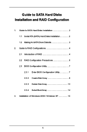
Guide to SATA Hard Disks Installation and RAID Configuration 1. Guide to SATA Hard Disks Installation 2 1.1 Serial ATA (SATA) Hard Disks Installation 2 1.2 Making An SATA Driver Diskette 3 2. Guide to RAID Configurations 4 2.1 Introduction of Windows 2000 / Windows XP 15 1 Installation of RAID 4 2.2 RAID Configuration Precautions 6 2.3 BIOS Configuration Utility 7 2.3.1 Enter BIOS Configuration Utility 7 2.3.2 Create Disk Array 8 2.3.3 Delete Disk Array 13 2.3.4 Select Boot Array 14 3.
Guide to SATA Hard Disks Installation and RAID Configuration 1. Guide to SATA Hard Disks Installation 2 1.1 Serial ATA (SATA) Hard Disks Installation 2 1.2 Making An SATA Driver Diskette 3 2. Guide to RAID Configurations 4 2.1 Introduction of Windows 2000 / Windows XP 15 1 Installation of RAID 4 2.2 RAID Configuration Precautions 6 2.3 BIOS Configuration Utility 7 2.3.1 Enter BIOS Configuration Utility 7 2.3.2 Create Disk Array 8 2.3.3 Delete Disk Array 13 2.3.4 Select Boot Array 14 3.

RAID Installation Guide
Page 3
.... (Do NOT insert any floppy diskette into the floppy drive, and press . Start to VIA RAID Tool", which is located in it! STEP 1: Insert the ASRock Support CD into your optical drive to install Windows 2000 / Windows XP on your system directly without setting the RAID configuration on your SATA HDDs..., you will start to use "VT8237 SATA RAID BIOS" to install Windows 2000 or Windows XP on the screen, "Do you will lose ALL data in the folder at the beginning of system boot...
.... (Do NOT insert any floppy diskette into the floppy drive, and press . Start to VIA RAID Tool", which is located in it! STEP 1: Insert the ASRock Support CD into your optical drive to install Windows 2000 / Windows XP on your system directly without setting the RAID configuration on your SATA HDDs..., you will start to use "VT8237 SATA RAID BIOS" to install Windows 2000 or Windows XP on the screen, "Do you will lose ALL data in the folder at the beginning of system boot...

RAID Installation Guide
Page 7
The main interface of BIOS configuration utility is as below: 7 2.3 BIOS Configuration Utility 2.3.1 Enter BIOS Configuration Utility After the system powers on, the following information will appear on the screen. Press 'Tab' key to enter BIOS configuration utility.
The main interface of BIOS configuration utility is as below: 7 2.3 BIOS Configuration Utility 2.3.1 Enter BIOS Configuration Utility After the system powers on, the following information will appear on the screen. Press 'Tab' key to enter BIOS configuration utility.

RAID Installation Guide
Page 9
One method is "Auto Setup", and another is "Select Disk Drives". Just highlight the target drives that you want to use and press to create a disk array. When using Select Disk Drives method, the channel column will be activated. There are two methods to select them respectively. 3. Select "Select Disk Drives" to the creation steps menu. 9 When all drives have been selected, press to go back to let user select the array drives manually. Select "Auto Setup" to allow BIOS to select the disk drives and create array automatically.
One method is "Auto Setup", and another is "Select Disk Drives". Just highlight the target drives that you want to use and press to create a disk array. When using Select Disk Drives method, the channel column will be activated. There are two methods to select them respectively. 3. Select "Select Disk Drives" to the creation steps menu. 9 When all drives have been selected, press to go back to let user select the array drives manually. Select "Auto Setup" to allow BIOS to select the disk drives and create array automatically.
User Manual
Page 3
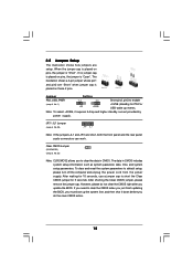
... 22 3.1 Introduction 22 3.1.1 BIOS Menu Bar 22 3.1.2 Navigation Keys 23 3.2 Main Screen 23 3.3 Advanced Screen 24 3.3.1 CPU Configuration 25 3.3.2 Chipset Configuration 27 3.3.3 ...Hardware Health Event Monitoring Screen 35 3.5 Boot Screen 35 3.5.1 Boot Settings Configuration 36 3 Contents 1 . Introduction 5 1.1 Package Contents 5 1.2 Specifications 6 1.3 Motherboard Layout 8 1.4 ASRock I/O PlusTM 9 2 . Installation 10 Pre-installation Precautions 10 2.1 CPU Installation 11 2.2 Installation of CPU Fan and Heatsink 11 2.3 Installation of Memory Modules (DIMM 12 2.4 Expansion...
... 22 3.1 Introduction 22 3.1.1 BIOS Menu Bar 22 3.1.2 Navigation Keys 23 3.2 Main Screen 23 3.3 Advanced Screen 24 3.3.1 CPU Configuration 25 3.3.2 Chipset Configuration 27 3.3.3 ...Hardware Health Event Monitoring Screen 35 3.5 Boot Screen 35 3.5.1 Boot Settings Configuration 36 3 Contents 1 . Introduction 5 1.1 Package Contents 5 1.2 Specifications 6 1.3 Motherboard Layout 8 1.4 ASRock I/O PlusTM 9 2 . Installation 10 Pre-installation Precautions 10 2.1 CPU Installation 11 2.2 Installation of CPU Fan and Heatsink 11 2.3 Installation of Memory Modules (DIMM 12 2.4 Expansion...

User Manual
Page 5
... Cable (Optional) 1 x Serial ATA (SATA) HDD Power Cable (Optional) 1 x ASRock I/O PlusTM Shield 1 x COM Port Bracket 1 x ASRock MR Card (Optional) 5 Because the motherboard specifications and the BIOS software might be available on ASRock website as well. Introduction Thank you for purchasing ASRock K8Upgrade-VM800 motherboard, a reliable motherboard produced under ASRock's consistently stringent quality control. In case any modifications of...
... Cable (Optional) 1 x Serial ATA (SATA) HDD Power Cable (Optional) 1 x ASRock I/O PlusTM Shield 1 x COM Port Bracket 1 x ASRock MR Card (Optional) 5 Because the motherboard specifications and the BIOS software might be available on ASRock website as well. Introduction Thank you for purchasing ASRock K8Upgrade-VM800 motherboard, a reliable motherboard produced under ASRock's consistently stringent quality control. In case any modifications of...
User Manual
Page 7
... may cause the instability of this motherboard offers stepless control, it back again. Frequencies other than the recommended CPU bus frequencies may cause permanent damage! 4. ASRock I/O PlusTM: 1 PS/2 Mouse Port, 1 PS/2 Keyboard Port 1 VGA Port 1 Parallel Port (ECP/EPP Support) 6 Ready-to-Use USB ...1 RJ-45 Port Audio Jack: Line In / Line Out / Microphone COM Port: 1 COM Port Header to support a COM port module BIOS: AMI Legal BIOS Supports "Plug and Play" ACPI 2.0 Compliance Wake Up Events SMBIOS 2.3.1 Support CPU Frequency Stepless Control (only for USB 2.0 works fine under...
... may cause the instability of this motherboard offers stepless control, it back again. Frequencies other than the recommended CPU bus frequencies may cause permanent damage! 4. ASRock I/O PlusTM: 1 PS/2 Mouse Port, 1 PS/2 Keyboard Port 1 VGA Port 1 Parallel Port (ECP/EPP Support) 6 Ready-to-Use USB ...1 RJ-45 Port Audio Jack: Line In / Line Out / Microphone COM Port: 1 COM Port Header to support a COM port module BIOS: AMI Legal BIOS Supports "Plug and Play" ACPI 2.0 Compliance Wake Up Events SMBIOS 2.3.1 Support CPU Frequency Stepless Control (only for USB 2.0 works fine under...

User Manual
Page 8
... 1.3 Motherboard Layout 123 45 22.9cm (9.0-in) PS2 Mouse PS2_USB_PW1 1 CPU_FAN1 ATX12V1 67 89 J15 1 IR1 1 PS2 Keyboard 4Mb BIOS Super I/O PARALLEL PORT ATXPWR1 FSB800 DDR2 (64/72 bit, 184-pin module) DDR1 (64/72 bit, 184-pin module) SOCKET 754... USB2.0 1 1 J7 J8 1 1 J5 J6 1 1 J3 J4 1 1 J1 J2 VIA K8M800 Chipset FUTURE_CPU_PORT1 1 J9 1 J10 AGP 8X 1.5V_AGP1 PCI 1 K8Upgrade-VM800 AUDIO CODEC AMR1 PCI 2 1 COM1 DDR400 FLOPPY1 IDE1 IDE2 VIA VT8237R Chipset SATA1 SATA2 CMOS Battery CLRCMOS2 1 CHA_FAN1 SPEAKER1 1 USB67 1 PLED PWRBTN PANEL 1 1 HDLED ...
... 1.3 Motherboard Layout 123 45 22.9cm (9.0-in) PS2 Mouse PS2_USB_PW1 1 CPU_FAN1 ATX12V1 67 89 J15 1 IR1 1 PS2 Keyboard 4Mb BIOS Super I/O PARALLEL PORT ATXPWR1 FSB800 DDR2 (64/72 bit, 184-pin module) DDR1 (64/72 bit, 184-pin module) SOCKET 754... USB2.0 1 1 J7 J8 1 1 J5 J6 1 1 J3 J4 1 1 J1 J2 VIA K8M800 Chipset FUTURE_CPU_PORT1 1 J9 1 J10 AGP 8X 1.5V_AGP1 PCI 1 K8Upgrade-VM800 AUDIO CODEC AMR1 PCI 2 1 COM1 DDR400 FLOPPY1 IDE1 IDE2 VIA VT8237R Chipset SATA1 SATA2 CMOS Battery CLRCMOS2 1 CHA_FAN1 SPEAKER1 1 USB67 1 PLED PWRBTN PANEL 1 1 HDLED ...
User Manual
Page 15
... higher standby current provided by power supply. Note: To select +5VSB, it down before you do not clear the CMOS right after you update the BIOS. Clear CMOS Jumper (CLRCMOS2) (see p.8, No. 1) +5V +5VSB +5VSB (standby) for 5 seconds. After shorting the Clear CMOS jumper, please remove the jumper cap. ...Jumper Setting PS2_USB_PWR1 1_2 2_3 Short pin2, pin3 to clear the CMOS when you just finish updating the BIOS, you to default setup, please turn off the computer and unplug the power cord from the power supply. The data in CMOS. If you...
... higher standby current provided by power supply. Note: To select +5VSB, it down before you do not clear the CMOS right after you update the BIOS. Clear CMOS Jumper (CLRCMOS2) (see p.8, No. 1) +5V +5VSB +5VSB (standby) for 5 seconds. After shorting the Clear CMOS jumper, please remove the jumper cap. ...Jumper Setting PS2_USB_PWR1 1_2 2_3 Short pin2, pin3 to clear the CMOS when you just finish updating the BIOS, you to default setup, please turn off the computer and unplug the power cord from the power supply. The data in CMOS. If you...

User Manual
Page 19
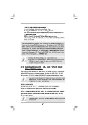
... still power-on and in the Support CD at the following path: ..\ RAID BIOS Setting Utility 19 STEP 4: Connect the other end of the SATA data cable to the SATA hard disk. 2.8 Hot Plug Function for SATA HDDs K8Upgrade-VM800 motherboard supports Hot Plug function for the action to insert and remove the...
... still power-on and in the Support CD at the following path: ..\ RAID BIOS Setting Utility 19 STEP 4: Connect the other end of the SATA data cable to the SATA hard disk. 2.8 Hot Plug Function for SATA HDDs K8Upgrade-VM800 motherboard supports Hot Plug function for the action to insert and remove the...
User Manual
Page 20
... your SATA HDDs with RAID functions, please follow the below steps. 20 After making a SATA driver diskette and using "SATA RAID BIOS" to set RAID configuration. Insert the ASRock Support CD into the floppy drive. D. STEP 1: Make a SATA Driver Diskette. During POST at the following path: .. \ ...SATA RAID BIOS STEP 3: Install Windows 2000 / Windows XP OS on the screen, "Do you need to format the floppy diskette and copy...
... your SATA HDDs with RAID functions, please follow the below steps. 20 After making a SATA driver diskette and using "SATA RAID BIOS" to set RAID configuration. Insert the ASRock Support CD into the floppy drive. D. STEP 1: Make a SATA Driver Diskette. During POST at the following path: .. \ ...SATA RAID BIOS STEP 3: Install Windows 2000 / Windows XP OS on the screen, "Do you need to format the floppy diskette and copy...
User Manual
Page 21
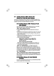
...the folder at the following path: .. \ VIA RAID Tool 1. B. Windows 98 / Windows ME does not support RAID functions. 2. STEP 1: Set Up BIOS. Enter BIOS SETUP UTILITY ¡÷Advanced screen ¡÷IDE Configuration. After the installation of SATA HDDs, please follow the below steps. Please install Windows 98...again so that "VIA RAID Tool" will be installed to your floppy drive. Copy the SATA 64-bit drivers to [non-RAID]. After setting up BIOS. Insert the floppy diskette into your system as well. 2.10 Installing Windows 98 / ME / 2000 / XP / XP 64-bit Without RAID ...
...the folder at the following path: .. \ VIA RAID Tool 1. B. Windows 98 / Windows ME does not support RAID functions. 2. STEP 1: Set Up BIOS. Enter BIOS SETUP UTILITY ¡÷Advanced screen ¡÷IDE Configuration. After the installation of SATA HDDs, please follow the below steps. Please install Windows 98...again so that "VIA RAID Tool" will be installed to your floppy drive. Copy the SATA 64-bit drivers to [non-RAID]. After setting up BIOS. Insert the floppy diskette into your system as well. 2.10 Installing Windows 98 / ME / 2000 / XP / XP 64-bit Without RAID ...
User Manual
Page 22
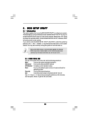
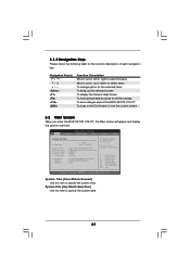
...system off and then back on the motherboard stores the BIOS SETUP UTILITY. BIOS SETUP UTILITY 3.1 Introduction This section explains how to use the BIOS SETUP UTILITY to enter the BIOS SETUP UTILITY, otherwise, POST will continue with the following BIOS setup screens and descriptions are for reference purpose only, and...on your system. The Flash Memory on . You may not exactly match what you see on the system chassis. Because the BIOS software is constantly being updated, the following selections: Main To set up the system time/date information Advanced To set up the advanced...
...system off and then back on the motherboard stores the BIOS SETUP UTILITY. BIOS SETUP UTILITY 3.1 Introduction This section explains how to use the BIOS SETUP UTILITY to enter the BIOS SETUP UTILITY, otherwise, POST will continue with the following BIOS setup screens and descriptions are for reference purpose only, and...on your system. The Flash Memory on . You may not exactly match what you see on the system chassis. Because the BIOS software is constantly being updated, the following selections: Main To set up the system time/date information Advanced To set up the advanced...
User Manual
Page 23
... Keys Please check the following table for all the settings To save changes and exit the BIOS SETUP UTILITY To jump to the Exit Screen or exit the current screen 3.2 Main Screen When you enter the BIOS SETUP UTILITY, the Main screen will appear and display the system overview... H/W Monitor Boot Security Exit System Overview System Time System Date [10:00:09] [Mon 11/08/2004] BIOS Version Processor Type Processor Speed L1 Cache Size L2 Cache Size Total Memory DIMM 1 DIMM 2 : K8Upgrade-VM800 BIOS P1.00 : AMD Athlon(tm) 64 Processor 3400+ : 2200 MHz : 128KB : 1024KB : 512MB with...
... Keys Please check the following table for all the settings To save changes and exit the BIOS SETUP UTILITY To jump to the Exit Screen or exit the current screen 3.2 Main Screen When you enter the BIOS SETUP UTILITY, the Main screen will appear and display the system overview... H/W Monitor Boot Security Exit System Overview System Time System Date [10:00:09] [Mon 11/08/2004] BIOS Version Processor Type Processor Speed L1 Cache Size L2 Cache Size Total Memory DIMM 1 DIMM 2 : K8Upgrade-VM800 BIOS P1.00 : AMD Athlon(tm) 64 Processor 3400+ : 2200 MHz : 128KB : 1024KB : 512MB with...

User Manual
Page 24
...IDE Configuration PCIPnP Configuration Floppy Configuration SuperIO Configuration USB Configuration Configure CPU Select Screen Select Item Enter Go to malfunction. 24 If ASRock 939CPU Board is installed into the FUTURE_CPU_PORT on this motherboard, you may cause system to select a field. Use [+] or ... Cache Size Total Memory DDR 1 (K8_939) DDR 2 (K8_939) DDR 3 (K8_939) DDR 4 (K8_939) [17:00:09] [Mon 11/08/2004] : K8Upgrade-VM800 BIOS P1.0 : AMD Athlon(tm) 64 Processor 3400+ : 2200 MHz : 128KB : 1024KB : 512MB with 64MB shared memory Single Channel Memory Mode : 512MB/133MHz (...
...IDE Configuration PCIPnP Configuration Floppy Configuration SuperIO Configuration USB Configuration Configure CPU Select Screen Select Item Enter Go to malfunction. 24 If ASRock 939CPU Board is installed into the FUTURE_CPU_PORT on this motherboard, you may cause system to select a field. Use [+] or ... Cache Size Total Memory DDR 1 (K8_939) DDR 2 (K8_939) DDR 3 (K8_939) DDR 4 (K8_939) [17:00:09] [Mon 11/08/2004] : K8Upgrade-VM800 BIOS P1.0 : AMD Athlon(tm) 64 Processor 3400+ : 2200 MHz : 128KB : 1024KB : 512MB with 64MB shared memory Single Channel Memory Mode : 512MB/133MHz (...
User Manual
Page 25
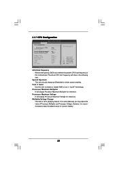
CPU Host Frequency While entering setup, BIOS auto detects the present CPU host frequency of Processor Multiplier and Processor Voltage. Processor Maximum Voltage It will display Processor Maximum Multiplier for reference.... Exit Exit v02.54 (C) Copyright 1985-2003, American Megatrends, Inc. The actual CPU host frequency will show in the following item. 3.3.1 CPU Configuration BIOS SETUP UTILITY Advanced CPU Configuration CPU Host Frequency Actual Frequency (MHz) Spread Spectrum Cool' n' Quiet Processor Maximum Multiplier Processor Maximum Voltage Multiplier/Voltage Change Memory...
CPU Host Frequency While entering setup, BIOS auto detects the present CPU host frequency of Processor Multiplier and Processor Voltage. Processor Maximum Voltage It will display Processor Maximum Multiplier for reference.... Exit Exit v02.54 (C) Copyright 1985-2003, American Megatrends, Inc. The actual CPU host frequency will show in the following item. 3.3.1 CPU Configuration BIOS SETUP UTILITY Advanced CPU Configuration CPU Host Frequency Actual Frequency (MHz) Spread Spectrum Cool' n' Quiet Processor Maximum Multiplier Processor Maximum Voltage Multiplier/Voltage Change Memory...

User Manual
Page 26
...]. You may set the value from [x4] up to [0.800V]. You may set the value from [1.550V] down to [x25] but no higher than [x11]. BIOS SETUP UTILITY Advanced CPU Configuration CPU Host Frequency Actual Frequency (MHz) Spread Spectrum Cool' n' Quiet Processor Maximum Multiplier Processor Maximum Voltage Multiplier/Voltage Change Processor...
...]. You may set the value from [x4] up to [0.800V]. You may set the value from [1.550V] down to [x25] but no higher than [x11]. BIOS SETUP UTILITY Advanced CPU Configuration CPU Host Frequency Actual Frequency (MHz) Spread Spectrum Cool' n' Quiet Processor Maximum Multiplier Processor Maximum Voltage Multiplier/Voltage Change Processor...
User Manual
Page 27
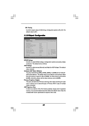
... Help Load Defaults Save and Exit Exit v02.54 (C) Copyright 1985-2003, American Megatrends, Inc. The default value is [2T]. 3.3.2 Chipset Configuration Advanced Chipset Settings BIOS SETUP UTILITY To set DRAM Voltage. The default value of this field at the default value unless the installed AGP card's specifications requires other sizes...
... Help Load Defaults Save and Exit Exit v02.54 (C) Copyright 1985-2003, American Megatrends, Inc. The default value is [2T]. 3.3.2 Chipset Configuration Advanced Chipset Settings BIOS SETUP UTILITY To set DRAM Voltage. The default value of this field at the default value unless the installed AGP card's specifications requires other sizes...

User Manual
Page 29
... item to select whether to repost video on AC/Power Loss This allows you to auto-detect or disable the Suspend-toRAM feature. 3.3.3 ACPI Configuration BIOS SETUP UTILITY Advanced ACPI Configuration Suspend To RAM Restore on the system from the power-soft-off mode. Repost Video on STR Resume This feature...
... item to select whether to repost video on AC/Power Loss This allows you to auto-detect or disable the Suspend-toRAM feature. 3.3.3 ACPI Configuration BIOS SETUP UTILITY Advanced ACPI Configuration Suspend To RAM Restore on the system from the power-soft-off mode. Repost Video on STR Resume This feature...
User Manual
Page 30
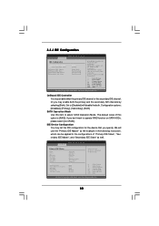
... you don't want to the configurations of "Primary IDE Slave", "Secondary IDE Master", and "Secondary IDE Slave" as well. 3.3.4 IDE Configuration BIOS SETUP UTILITY Advanced IDE Configuration OnBoard IDE Controller SATA Operation Mode Primary IDE Master Primary IDE Slave Secondary IDE Master Secondary IDE Slave [Both] [RAID...Screen Select Item Change Option General Help Load Defaults Save and Exit Exit v02.54 (C) Copyright 1985-2003, American Megatrends, Inc. BIOS SETUP UTILITY Advanced Primary IDE Master Device Vendor Size LBA Mode Block Mode PIO Mode Async DMA Ultra DMA S.M.A.R.T.
... you don't want to the configurations of "Primary IDE Slave", "Secondary IDE Master", and "Secondary IDE Slave" as well. 3.3.4 IDE Configuration BIOS SETUP UTILITY Advanced IDE Configuration OnBoard IDE Controller SATA Operation Mode Primary IDE Master Primary IDE Slave Secondary IDE Master Secondary IDE Slave [Both] [RAID...Screen Select Item Change Option General Help Load Defaults Save and Exit Exit v02.54 (C) Copyright 1985-2003, American Megatrends, Inc. BIOS SETUP UTILITY Advanced Primary IDE Master Device Vendor Size LBA Mode Block Mode PIO Mode Async DMA Ultra DMA S.M.A.R.T.


