User Manual
Page 3
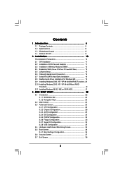
Installation 10 Pre-installation Precautions 10 2.1 CPU Installation 11 2.2 Installation of CPU Fan and Heatsink 11 2.3 Installation of Memory Modules (DIMM 12 2.4 Expansion Slots (Future CPU Port, PCI and AGP Slots 13 2.5 Jumpers Setup 15 2.6 Onboard Headers and Connectors 16 2.7 Serial ATA (SATA) Hard ... 3.4 Hardware Health Event Monitoring Screen 35 3.5 Boot Screen 36 3.5.1 Boot Settings Configuration 36 3.6 Security Screen 37 3.7 Exit Screen 38 3 Introduction 5 1.1 Package Contents 5 1.2 Specifications 6 1.3 Motherboard Layout 8 1.4 ASRock 8CH I/O 9 2 .
Installation 10 Pre-installation Precautions 10 2.1 CPU Installation 11 2.2 Installation of CPU Fan and Heatsink 11 2.3 Installation of Memory Modules (DIMM 12 2.4 Expansion Slots (Future CPU Port, PCI and AGP Slots 13 2.5 Jumpers Setup 15 2.6 Onboard Headers and Connectors 16 2.7 Serial ATA (SATA) Hard ... 3.4 Hardware Health Event Monitoring Screen 35 3.5 Boot Screen 36 3.5.1 Boot Settings Configuration 36 3.6 Security Screen 37 3.7 Exit Screen 38 3 Introduction 5 1.1 Package Contents 5 1.2 Specifications 6 1.3 Motherboard Layout 8 1.4 ASRock 8CH I/O 9 2 .
User Manual
Page 5
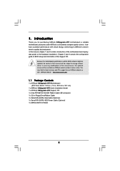
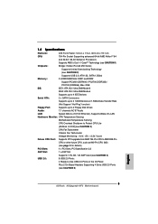
... configuration guide to quality and endurance. You may find the latest memory and CPU support lists on ASRock website without notice. ASRock website http://www.asrock.com 1.1 Package Contents 1 x ASRock K8Upgrade-NF3 Motherboard (ATX Form Factor: 12.0-in x 7.5-in, 30.5 cm x 19.1 cm) 1 x ASRock K8Upgrade-NF3 Quick Installation Guide 1 x ASRock K8Upgrade-NF3 Support CD 1 x Ultra ATA 66/100/133 IDE Ribbon Cable (80...
... configuration guide to quality and endurance. You may find the latest memory and CPU support lists on ASRock website without notice. ASRock website http://www.asrock.com 1.1 Package Contents 1 x ASRock K8Upgrade-NF3 Motherboard (ATX Form Factor: 12.0-in x 7.5-in, 30.5 cm x 19.1 cm) 1 x ASRock K8Upgrade-NF3 Quick Installation Guide 1 x ASRock K8Upgrade-NF3 Support CD 1 x Ultra ATA 66/100/133 IDE Ribbon Cable (80...
User Manual
Page 6
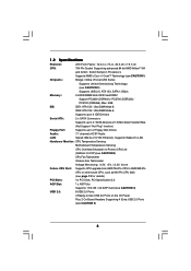
...QuietTM Technology (see CAUTION 1) Chipsets: Bridge: nVidia nForce3 250 Series Supports Untied Overclocking Technology (see CAUTION 2) Supports USB 2.0, ATA 133, SATA 1.5Gb/s Memory: 2 x DDR DIMM Slots: DDR1 and DDR2 Support PC3200 (DDR400) / PC2700 (DDR333) / PC2100 (DDR266), Max. 2GB IDE: IDE1: ATA ...100 Ethernet), Supports Wake-On-LAN Hardware Monitor: CPU Temperature Sensing Motherboard Temperature Sensing CPU Overheat Shutdown to Protect CPU Life (ASRock U-COP)(see CAUTION 3) CPU Fan Tachometer Chassis Fan Tachometer Voltage Monitoring: +12V, +5V, +3.3V, Vcore Future CPU ...
...QuietTM Technology (see CAUTION 1) Chipsets: Bridge: nVidia nForce3 250 Series Supports Untied Overclocking Technology (see CAUTION 2) Supports USB 2.0, ATA 133, SATA 1.5Gb/s Memory: 2 x DDR DIMM Slots: DDR1 and DDR2 Support PC3200 (DDR400) / PC2700 (DDR333) / PC2100 (DDR266), Max. 2GB IDE: IDE1: ATA ...100 Ethernet), Supports Wake-On-LAN Hardware Monitor: CPU Temperature Sensing Motherboard Temperature Sensing CPU Overheat Shutdown to Protect CPU Life (ASRock U-COP)(see CAUTION 3) CPU Fan Tachometer Chassis Fan Tachometer Voltage Monitoring: +12V, +5V, +3.3V, Vcore Future CPU ...
User Manual
Page 12
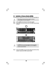
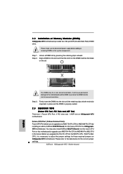
... you force the DIMM into the slot until the retaining clips at incorrect orientation. Unlock a DIMM slot by pressing the retaining clips outward. 2.3 Installation of Memory Modules (DIMM) This motherboard is properly seated. 12 It will cause permanent damage to disconnect power supply before adding or removing DIMMs or the system...
... you force the DIMM into the slot until the retaining clips at incorrect orientation. Unlock a DIMM slot by pressing the retaining clips outward. 2.3 Installation of Memory Modules (DIMM) This motherboard is properly seated. 12 It will cause permanent damage to disconnect power supply before adding or removing DIMMs or the system...
User Manual
Page 22
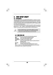
... bar, and then press to configure your screen. 3.1.1 BIOS Menu Bar The top of the screen has a menu bar with its test routines. The Flash Memory on . If you start up the security features Exit To exit the current screen or the BIOS SETUP UTILITY Use < > key or < > key to enter...
... bar, and then press to configure your screen. 3.1.1 BIOS Menu Bar The top of the screen has a menu bar with its test routines. The Flash Memory on . If you start up the security features Exit To exit the current screen or the BIOS SETUP UTILITY Use < > key or < > key to enter...

User Manual
Page 23
...BIOS SETUP UTILITY Main Advanced H/W Monitor Boot Security Exit System Overview System Time System Date [17:00:09] [Tue 05/31/2005] BIOS Version : K8Upgrade-NF3 BIOS P1.0 Processor Type : AMD Athlon(tm) 64 Processor 3400+ Processor Speed : 2200 MHz Microcode Update : F7A/3A L1 Cache Size : 128KB... L2 Cache Size : 1024KB Total Memory DDR 1 DDR 2 : 256MB : 256MB/166MHz (DDR333) : None Use [Enter], [TAB] or [SHIFT-TAB] to specify the system time. Use [+] or ...
...BIOS SETUP UTILITY Main Advanced H/W Monitor Boot Security Exit System Overview System Time System Date [17:00:09] [Tue 05/31/2005] BIOS Version : K8Upgrade-NF3 BIOS P1.0 Processor Type : AMD Athlon(tm) 64 Processor 3400+ Processor Speed : 2200 MHz Microcode Update : F7A/3A L1 Cache Size : 128KB... L2 Cache Size : 1024KB Total Memory DDR 1 DDR 2 : 256MB : 256MB/166MHz (DDR333) : None Use [Enter], [TAB] or [SHIFT-TAB] to specify the system time. Use [+] or ...
User Manual
Page 24
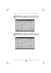
.../31/2005] BIOS Version Processor Type Processor Speed Microcode Update L1 Cache Size L2 Cache Size : K8Upgrade-NF3 BIOS P1.0 : AMD Athlon(tm) 64 Processor 3400+ : 2200 MHz : F7A/3A : 128KB : 1024KB Total Memory : 256MB Single-Channel Memory Mode DDR 1 (K8_939) : 256MB/166MHz (DDR333) DDR 2 (K8_939) : None DDR 3 (K8_939)...Exit Exit v02.54 (C) Copyright 1985-2003, American Megatrends, Inc. 24 Use [+] or [-] to select a field. If ASRock M2CPU Board is installed into the FUTURE_CPU_PORT on this motherboard, you will see the below Main screen when entering the BIOS SETUP UTILITY....
.../31/2005] BIOS Version Processor Type Processor Speed Microcode Update L1 Cache Size L2 Cache Size : K8Upgrade-NF3 BIOS P1.0 : AMD Athlon(tm) 64 Processor 3400+ : 2200 MHz : F7A/3A : 128KB : 1024KB Total Memory : 256MB Single-Channel Memory Mode DDR 1 (K8_939) : 256MB/166MHz (DDR333) DDR 2 (K8_939) : None DDR 3 (K8_939)...Exit Exit v02.54 (C) Copyright 1985-2003, American Megatrends, Inc. 24 Use [+] or [-] to select a field. If ASRock M2CPU Board is installed into the FUTURE_CPU_PORT on this motherboard, you will see the below Main screen when entering the BIOS SETUP UTILITY....

User Manual
Page 26
... Configuration Overclock Mode CPU Frequency (MHz) AGP Frequency (MHz) Boot Failure Guard Spread Spectrum Cool' n' Quiet Processor Maximum Multiplier Processor Maximum Voltage Multiplier/Voltage Change Memory Clock Flexibility Option Burst Length CAS Latency (CL) TRCD TRAS TRP [Auto] [200] [66] [Enabled] [Auto] [Enabled] x11 1.550 V [Auto] [Auto] [Disabled] [8 Beats] [Auto] [Auto...
... Configuration Overclock Mode CPU Frequency (MHz) AGP Frequency (MHz) Boot Failure Guard Spread Spectrum Cool' n' Quiet Processor Maximum Multiplier Processor Maximum Voltage Multiplier/Voltage Change Memory Clock Flexibility Option Burst Length CAS Latency (CL) TRCD TRAS TRP [Auto] [200] [66] [Enabled] [Auto] [Enabled] x11 1.550 V [Auto] [Auto] [Disabled] [8 Beats] [Auto] [Auto...

User Manual
Page 27
...[2.5]. Configuration options: [Auto], [2CLK], [3CLK], [4CLK], [5CLK], and [6CLK]. However, for memory compatibility when it will be hidden. The default value is [Auto]. Memory Clock This item can be [x11] even if you set the value from [x8] up to [x25...MHz) AGP Frequency (MHz) Boot Failure Guard Spread Spectrum Cool' n' Quiet Processor Maximum Multiplier Processor Maximum Voltage Multiplier/Voltage Change Processor Multiplier Processor Voltage Memory Clock Flexibility Option Burst Length CAS Latency (CL) TRCD [Auto] [200] [66] [Enabled] [Auto] [Enabled] x11 1.550 V [...
...[2.5]. Configuration options: [Auto], [2CLK], [3CLK], [4CLK], [5CLK], and [6CLK]. However, for memory compatibility when it will be hidden. The default value is [Auto]. Memory Clock This item can be [x11] even if you set the value from [x8] up to [x25...MHz) AGP Frequency (MHz) Boot Failure Guard Spread Spectrum Cool' n' Quiet Processor Maximum Multiplier Processor Maximum Voltage Multiplier/Voltage Change Processor Multiplier Processor Voltage Memory Clock Flexibility Option Burst Length CAS Latency (CL) TRCD [Auto] [200] [66] [Enabled] [Auto] [Enabled] x11 1.550 V [...
User Manual
Page 28
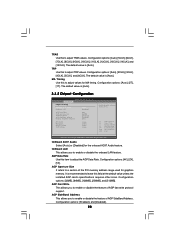
...], [9CLK], [10CLK], [11CLK], [12CLK], [13CLK], [14CLK], and [15CLK]. AGP Aperture Size It refers to a section of the PCI memory address range used for the onboard AC97 Audio feature. The default value is [Auto]. 3.3.2 Chipset Configuration BIOS SETUP UTILITY Advanced Chipset Settings OnBoard AC97 Audio...256MB], and [512MB]. Configuration options: [Enabled], and [Disabled]. 28 OnBoard AC97 Audio Select [Auto] or [Disabled] for graphics memory. AGP Fast Write This allows you to enable or disable the onboard LAN feature. TRAS Use this item to adjust the AGP Data Rate....
...], [9CLK], [10CLK], [11CLK], [12CLK], [13CLK], [14CLK], and [15CLK]. AGP Aperture Size It refers to a section of the PCI memory address range used for the onboard AC97 Audio feature. The default value is [Auto]. 3.3.2 Chipset Configuration BIOS SETUP UTILITY Advanced Chipset Settings OnBoard AC97 Audio...256MB], and [512MB]. Configuration options: [Enabled], and [Disabled]. 28 OnBoard AC97 Audio Select [Auto] or [Disabled] for graphics memory. AGP Fast Write This allows you to enable or disable the onboard LAN feature. TRAS Use this item to adjust the AGP Data Rate....
Quick Installation Guide
Page 2
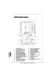
... Port Header (GAME1) 22 Front Panel Audio Header (AUDIO1) 23 JR1 JL1 Jumper 24 PCI Slots (PCI1- 4) 25 Internal Audio Connector: CD1 (Black) 26 Flash Memory 27 Infrared Module Header (IR1) 28 J15 Jumper 29 J9 / J10 Jumper 30 Future CPU Port (FUTURE_CPU_PORT1) 31 J1-J8 Jumpers 2 ASRock K8Upgrade-NF3 Motherboard
... Port Header (GAME1) 22 Front Panel Audio Header (AUDIO1) 23 JR1 JL1 Jumper 24 PCI Slots (PCI1- 4) 25 Internal Audio Connector: CD1 (Black) 26 Flash Memory 27 Infrared Module Header (IR1) 28 J15 Jumper 29 J9 / J10 Jumper 30 Future CPU Port (FUTURE_CPU_PORT1) 31 J1-J8 Jumpers 2 ASRock K8Upgrade-NF3 Motherboard
Quick Installation Guide
Page 4
... 1 x ASRock K8Upgrade-NF3 Motherboard (ATX Form Factor: 12.0-in x 7.5-in, 30.5 cm x 19.1 cm) 1 x ASRock K8Upgrade-NF3 Quick Installation Guide 1 x ASRock K8Upgrade-NF3 Support CD 1 x Ultra ATA 66/100/133 IDE Ribbon Cable (80-conductor) 1 x 3.5-in the Support CD. It delivers excellent performance with robust design conforming to ASRock's commitment to change without further notice. You may find the latest memory...
... 1 x ASRock K8Upgrade-NF3 Motherboard (ATX Form Factor: 12.0-in x 7.5-in, 30.5 cm x 19.1 cm) 1 x ASRock K8Upgrade-NF3 Quick Installation Guide 1 x ASRock K8Upgrade-NF3 Support CD 1 x Ultra ATA 66/100/133 IDE Ribbon Cable (80-conductor) 1 x 3.5-in the Support CD. It delivers excellent performance with robust design conforming to ASRock's commitment to change without further notice. You may find the latest memory...
Quick Installation Guide
Page 5
...Chipsets: Bridge: nVidia nForce3 250 Series Supports Untied Overclocking Technology (see CAUTION 2) Supports USB 2.0, ATA 133, SATA 1.5Gb/s Memory: 2 x DDR DIMM Slots: DDR1 and DDR2 Support PC3200 (DDR400) / PC2700 (DDR333) / PC2100 (DDR266), Max. ...LAN Hardware Monitor: CPU Temperature Sensing Motherboard Temperature Sensing CPU Overheat Shutdown to Protect CPU Life (ASRock U-COP)(see CAUTION 3) CPU Fan Tachometer Chassis Fan Tachometer Voltage Monitoring: +12V, +5V, ... On-Board Headers Supporting 4 Extra USB 2.0 Ports (see CAUTION 5) English 5 ASRock K8Upgrade-NF3 Motherboard
...Chipsets: Bridge: nVidia nForce3 250 Series Supports Untied Overclocking Technology (see CAUTION 2) Supports USB 2.0, ATA 133, SATA 1.5Gb/s Memory: 2 x DDR DIMM Slots: DDR1 and DDR2 Support PC3200 (DDR400) / PC2700 (DDR333) / PC2100 (DDR266), Max. ...LAN Hardware Monitor: CPU Temperature Sensing Motherboard Temperature Sensing CPU Overheat Shutdown to Protect CPU Life (ASRock U-COP)(see CAUTION 3) CPU Fan Tachometer Chassis Fan Tachometer Voltage Monitoring: +12V, +5V, ... On-Board Headers Supporting 4 Extra USB 2.0 Ports (see CAUTION 5) English 5 ASRock K8Upgrade-NF3 Motherboard
Quick Installation Guide
Page 8
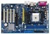
...) There are 1 Future CPU Port, 4 PCI slots and 1 AGP slot on K8Upgrade-NF3 motherboard. Please refer to adjust the jumper settings for the correct jumper settings. 8 ASRock K8Upgrade-NF3 Motherboard English Step 1. It will cause permanent damage to disconnect power supply before adding or...outward. Unlock a DIMM slot by installing an add-on ASRock 939CPU Board into this future CPU Port on this future CPU Port on the slot. NF3 motherboard. Step 2. Step 3. 2.2 Installation of Memory Modules (DIMM) K8Upgrade-NF3 motherboard provides two 184-pin DDR (Double Data Rate)...
...) There are 1 Future CPU Port, 4 PCI slots and 1 AGP slot on K8Upgrade-NF3 motherboard. Please refer to adjust the jumper settings for the correct jumper settings. 8 ASRock K8Upgrade-NF3 Motherboard English Step 1. It will cause permanent damage to disconnect power supply before adding or...outward. Unlock a DIMM slot by installing an add-on ASRock 939CPU Board into this future CPU Port on this future CPU Port on the slot. NF3 motherboard. Step 2. Step 3. 2.2 Installation of Memory Modules (DIMM) K8Upgrade-NF3 motherboard provides two 184-pin DDR (Double Data Rate)...
Quick Installation Guide
Page 16
...-Test (POST) to scroll through its test routines. 3. EXE" from the "BIN" folder in the Support CD to be user-friendly. BIOS Information The Flash Memory on the file "ASSETUP. The BIOS Setup program is a menu-driven program, which allows you to enter BIOS Setup utility; If the Main Menu does... enabled in the Support CD. 4. To begin using the Support CD, insert the CD into your computer. It is designed to display the menus. 16 ASRock K8Upgrade-NF3 Motherboard English
...-Test (POST) to scroll through its test routines. 3. EXE" from the "BIN" folder in the Support CD to be user-friendly. BIOS Information The Flash Memory on the file "ASSETUP. The BIOS Setup program is a menu-driven program, which allows you to enter BIOS Setup utility; If the Main Menu does... enabled in the Support CD. 4. To begin using the Support CD, insert the CD into your computer. It is designed to display the menus. 16 ASRock K8Upgrade-NF3 Motherboard English

