
User Manual
Page 3
... Display Features 26 2.7 HDMI Audio Function Operation Guide 29 2.8 Jumpers Setup 30 2.9 Onboard Headers and Connectors 31 2.10 HDMI_SPDIF Header Connection Guide 37 2.11 eSATAII Interface Introduction (Only for K10N78-1394) ......... 38 2.12 SATAII Hard Disk Setup Guide 41 2.13 Serial ATA (SATA) / Serial ATAII (SATAII) Hard Disks ... (BD) / HD-DVD Playback Support 11 1.4 Passed 1080p Blu-ray (BD) / HD-DVD Films in Our Lab Test ... 12 1.5 Motherboard Layout (K10N78-1394 13 1.6 Motherboard Layout (K10N78 14 1.7 I/O Panel (K10N78-1394 15 1.8 I/O Panel (K10N78 16 2 . Contents 1 .
... Display Features 26 2.7 HDMI Audio Function Operation Guide 29 2.8 Jumpers Setup 30 2.9 Onboard Headers and Connectors 31 2.10 HDMI_SPDIF Header Connection Guide 37 2.11 eSATAII Interface Introduction (Only for K10N78-1394) ......... 38 2.12 SATAII Hard Disk Setup Guide 41 2.13 Serial ATA (SATA) / Serial ATAII (SATAII) Hard Disks ... (BD) / HD-DVD Playback Support 11 1.4 Passed 1080p Blu-ray (BD) / HD-DVD Films in Our Lab Test ... 12 1.5 Motherboard Layout (K10N78-1394 13 1.6 Motherboard Layout (K10N78 14 1.7 I/O Panel (K10N78-1394 15 1.8 I/O Panel (K10N78 16 2 . Contents 1 .
User Manual
Page 15
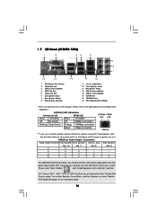
.... Please select "Mixer ToolBox" , click "Enable playback multi-streaming", and click "ok". TABLE for connection details in accordance with the type of speaker you are two LED next to the LAN port. Please ... -- -- 4 V V -- -- 6 V V V -- 8 V V V V To enable Multi-Streaming function, you will find "Mixer" tool on your computer, you need to connect a front panel audio cable to the front panel audio header. 1.7 I/O Panel (K10N78-1394) 1 2 34 5 6 9 7 10 8 11 16 15 14 1 PS/2 Mouse Port (Green) 2 VGA/D-Sub Port 3 USB 2.0 Ports (USB45) 4 IEEE 1394 Port *...
.... Please select "Mixer ToolBox" , click "Enable playback multi-streaming", and click "ok". TABLE for connection details in accordance with the type of speaker you are two LED next to the LAN port. Please ... -- -- 4 V V -- -- 6 V V V -- 8 V V V V To enable Multi-Streaming function, you will find "Mixer" tool on your computer, you need to connect a front panel audio cable to the front panel audio header. 1.7 I/O Panel (K10N78-1394) 1 2 34 5 6 9 7 10 8 11 16 15 14 1 PS/2 Mouse Port (Green) 2 VGA/D-Sub Port 3 USB 2.0 Ports (USB45) 4 IEEE 1394 Port *...
User Manual
Page 16
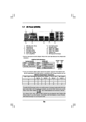
...Status Description Status Description ACT/LINK SPEED LED LED Off No Activity Off 10Mbps connection Blinking Data Activity Orange 100Mbps connection Green 1Gbps connection LAN Port ** If you use . After restarting your computer, you will ...No. 6) (No. 4) 2 V -- -- -- 4 V V -- -- 6 V V V -- 8 V V V V To enable Multi-Streaming function, you need to connect a front panel audio cable to use front panel audio. 16 1.7 I/O Panel (K10N78) 1 2 3 4 7 5 8 6 9 14 13 12 11 10 1 PS/2 Mouse Port (Green) 2 VGA/D-Sub Port * 3 LAN RJ-45 Port 4 Side Speaker ...
...Status Description Status Description ACT/LINK SPEED LED LED Off No Activity Off 10Mbps connection Blinking Data Activity Orange 100Mbps connection Green 1Gbps connection LAN Port ** If you use . After restarting your computer, you will ...No. 6) (No. 4) 2 V -- -- -- 4 V V -- -- 6 V V V -- 8 V V V V To enable Multi-Streaming function, you need to connect a front panel audio cable to use front panel audio. 16 1.7 I/O Panel (K10N78) 1 2 3 4 7 5 8 6 9 14 13 12 11 10 1 PS/2 Mouse Port (Green) 2 VGA/D-Sub Port * 3 LAN RJ-45 Port 4 Side Speaker ...
User Manual
Page 26
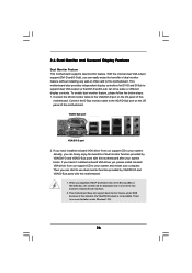
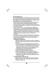
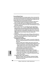
... and D-Sub), you can freely enjoy the benefits of dual monitor function provided by VGA/DVI-D and VGA/D-Sub ports with this motherboard. Connect the D-Sub monitor cable to your system and restart your system boots. To enable dual monitor feature, please follow the below steps: 1. If...start to this motherboard. When you can easily enjoy the benefits of this motherboard after your computer. Connect the DVI-D monitor cable to the VGA/DVI-D port on the I /O panel of dual monitor feature without installing any add-on VGA card to use dual monitor function provided by ...
... and D-Sub), you can freely enjoy the benefits of dual monitor function provided by VGA/DVI-D and VGA/D-Sub ports with this motherboard. Connect the D-Sub monitor cable to your system and restart your system boots. To enable dual monitor feature, please follow the below steps: 1. If...start to this motherboard. When you can easily enjoy the benefits of this motherboard after your computer. Connect the DVI-D monitor cable to the VGA/DVI-D port on the I /O panel of dual monitor feature without installing any add-on VGA card to use dual monitor function provided by ...
User Manual
Page 27
... the number 2. Install the NVIDIA® PCI Express VGA card to page 21 for proper expansion card installation procedures for details. 2. C. E. Connect the D-Sub monitor cable to enable the function of this motherboard. 4. Right-click the display icon in the Display Properties dialog that you select ...], [128MB], [256MB] or [512MB] to the VGA/D-Sub port on the I /O panel of VGA/D-sub. If you do not adjust the BIOS setup, the default value of the multi-monitor according to this motherboard. G. Connect the DVI-D monitor cable to the VGA/DVI-D port on VGA card is no...
... the number 2. Install the NVIDIA® PCI Express VGA card to page 21 for proper expansion card installation procedures for details. 2. C. E. Connect the D-Sub monitor cable to enable the function of this motherboard. 4. Right-click the display icon in the Display Properties dialog that you select ...], [128MB], [256MB] or [512MB] to the VGA/D-Sub port on the I /O panel of VGA/D-sub. If you do not adjust the BIOS setup, the default value of the multi-monitor according to this motherboard. G. Connect the DVI-D monitor cable to the VGA/DVI-D port on VGA card is no...

User Manual
Page 32
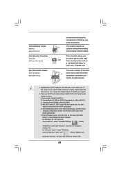
For K10N78-1394, you to the power supply USB 2.0 Headers (9-pin USB8_9) (see p.13/14 No. 14) (9-pin USB6_7) (see p.13/14 No. 15) USB/WiFi Header (11-pin USB/WIFI) (see p.13, No. 36) Serial ATA (SATA) Data Cable (Optional) Serial ATA (SATA) Power Cable (Optional) connect to ... Besides six default USB 2.0 ports on the I/O panel, there are two USB 2.0 headers on each drive. The current eSATAII interface allows up to connect SATAII_6 (PORT5) connector and eSATAII connector. This header can be used to support WiFi+AP function with ASRock WiFi-802. 11g or WiFi-802.11n module, ...
For K10N78-1394, you to the power supply USB 2.0 Headers (9-pin USB8_9) (see p.13/14 No. 14) (9-pin USB6_7) (see p.13/14 No. 15) USB/WiFi Header (11-pin USB/WIFI) (see p.13, No. 36) Serial ATA (SATA) Data Cable (Optional) Serial ATA (SATA) Power Cable (Optional) connect to ... Besides six default USB 2.0 ports on the I/O panel, there are two USB 2.0 headers on each drive. The current eSATAII interface allows up to connect SATAII_6 (PORT5) connector and eSATAII connector. This header can be used to support WiFi+AP function with ASRock WiFi-802. 11g or WiFi-802.11n module, ...
User Manual
Page 33
... Windows system. C. E. Click the icon on the chassis must support HDA to the front panel audio header as a CD-ROM, DVD-ROM, TV tuner card, or MPEG card. Connect Audio_R (RIN) to OUT2_R and Audio_L (LIN) to MIC2_L. MIC_RET and OUT_RET are for AC...) GND PRESENCE# MIC_RET OUT_RET 1 OUT2_L J_SENSE OUT2_R MIC2_R MIC2_L This is an interface for the front panel audio cable that allows convenient connection and control of wireless network connectivity. Connect Mic_IN (MIC) to OUT2_L. This header supports an optional wireless transmitting and receiving infrared module. Please ...
... Windows system. C. E. Click the icon on the chassis must support HDA to the front panel audio header as a CD-ROM, DVD-ROM, TV tuner card, or MPEG card. Connect Audio_R (RIN) to OUT2_R and Audio_L (LIN) to MIC2_L. MIC_RET and OUT_RET are for AC...) GND PRESENCE# MIC_RET OUT_RET 1 OUT2_L J_SENSE OUT2_R MIC2_R MIC2_L This is an interface for the front panel audio cable that allows convenient connection and control of wireless network connectivity. Connect Mic_IN (MIC) to OUT2_L. This header supports an optional wireless transmitting and receiving infrared module. Please ...
User Manual
Page 34
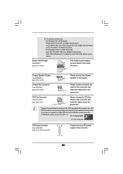
... CPU fan cable to hear your voice through front mic, please deselect "Mute" icon in the Realtek Control panel. If you want to this header. Please connect the chassis speaker to this connector and match the black wire to Pin 1-3. G. To activate the front mic. CPU Fan Connector...1 SPEAKER DUMMY DUMMY +5V GND +12V CHA_FAN_SPEED This header accommodates several system front panel functions. Please connect a chassis fan cable to this motherboard, please connect it to the ground pin. If you plan to connect the 3-Pin CPU fan to the CPU fan connector on this connector and match ...
... CPU fan cable to hear your voice through front mic, please deselect "Mute" icon in the Realtek Control panel. If you want to this header. Please connect the chassis speaker to this connector and match the black wire to Pin 1-3. G. To activate the front mic. CPU Fan Connector...1 SPEAKER DUMMY DUMMY +5V GND +12V CHA_FAN_SPEED This header accommodates several system front panel functions. Please connect a chassis fan cable to this motherboard, please connect it to the ground pin. If you plan to connect the 3-Pin CPU fan to the CPU fan connector on this connector and match ...

User Manual
Page 35
... the 4-pin ATX power supply, please plug your power supply along with ATX 12V plug to connect HDMI Digital TV/ projector/LCD devices. Besides one default IEEE 1394 port on the I/O panel, there is necessary to connect a power supply with Pin 1 and Pin 5. 4-Pin ATX 12V Power Supply Installation 1 5 Serial ...) (see p.13/14, No. 29) 1 GND SPDIFOUT +5V SPDIF audio output to HDMI VGA card, allows the system to this connector. Please connect the HDMI_SPDIF connector of HDMI VGA card to do so will cause power up failure. This IEEE 1394 header can support one IEEE 1394 header...
... the 4-pin ATX power supply, please plug your power supply along with ATX 12V plug to connect HDMI Digital TV/ projector/LCD devices. Besides one default IEEE 1394 port on the I/O panel, there is necessary to connect a power supply with Pin 1 and Pin 5. 4-Pin ATX 12V Power Supply Installation 1 5 Serial ...) (see p.13/14, No. 29) 1 GND SPDIFOUT +5V SPDIF audio output to HDMI VGA card, allows the system to this connector. Please connect the HDMI_SPDIF connector of HDMI VGA card to do so will cause power up failure. This IEEE 1394 header can support one IEEE 1394 header...

Quick Installation Guide
Page 4
..."Mixer" tool on your computer, you use 2-channel speaker, please connect the speaker's plug into "Front Speaker Jack". Please select "Mixer ToolBox" , click "Enable playback multi-streaming", and click "ok". After restarting your system. I/O Panel (K10N78-1394) 1 PS/2 Mouse Port (Green) 2 VGA/D-Sub Port ...panel audio header. Choose "2CH", "4CH", "6CH", or "8CH" and then you are two LED next to the table below for connection details in accordance with the type of speaker you need to connect a front panel audio cable to use front panel audio. 4 ASRock K10N78-1394 / K10N78...
..."Mixer" tool on your computer, you use 2-channel speaker, please connect the speaker's plug into "Front Speaker Jack". Please select "Mixer ToolBox" , click "Enable playback multi-streaming", and click "ok". After restarting your system. I/O Panel (K10N78-1394) 1 PS/2 Mouse Port (Green) 2 VGA/D-Sub Port ...panel audio header. Choose "2CH", "4CH", "6CH", or "8CH" and then you are two LED next to the table below for connection details in accordance with the type of speaker you need to connect a front panel audio cable to use front panel audio. 4 ASRock K10N78-1394 / K10N78...

Quick Installation Guide
Page 5
... playback multi-streaming", and click "ok". See the table below for connection details in accordance with the type of speaker you are two LED next to the LAN port. I/O Panel (K10N78) T/LINK SPEED ED LED LAN Port 1 PS/2 Mouse Port (Green...panel audio. 5 ASRock K10N78-1394 / K10N78 Motherboard English After restarting your computer, you use . LAN Port LED Indications Activity/Link LED SPEED LED Status Description Status Description ACT/LINK SPEED LED LED Off No Activity Off 10Mbps connection Blinking Data Activity Orange 100Mbps connection Green 1Gbps connection...
... playback multi-streaming", and click "ok". See the table below for connection details in accordance with the type of speaker you are two LED next to the LAN port. I/O Panel (K10N78) T/LINK SPEED ED LED LAN Port 1 PS/2 Mouse Port (Green...panel audio. 5 ASRock K10N78-1394 / K10N78 Motherboard English After restarting your computer, you use . LAN Port LED Indications Activity/Link LED SPEED LED Status Description Status Description ACT/LINK SPEED LED LED Off No Activity Off 10Mbps connection Blinking Data Activity Orange 100Mbps connection Green 1Gbps connection...
Quick Installation Guide
Page 23
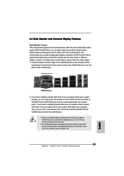
... VGA card to this motherboard. This motherboard also provides independent display controllers for DVI-D and D-Sub to the VGA/DVI-D port on the I /O panel of both monitors. 2. Connect the D-Sub monitor cable to your system and restart your system already, you can freely enjoy the benefits of this motherboard. If you playback... DOS because in one of the two monitors instead of this situation, the VGA/DVI-D output is no such limitation under Windows® OS. 23 ASRock K10N78-1394 / K10N78 Motherboard English
... VGA card to this motherboard. This motherboard also provides independent display controllers for DVI-D and D-Sub to the VGA/DVI-D port on the I /O panel of both monitors. 2. Connect the D-Sub monitor cable to your system and restart your system already, you can freely enjoy the benefits of this motherboard. If you playback... DOS because in one of the two monitors instead of this situation, the VGA/DVI-D output is no such limitation under Windows® OS. 23 ASRock K10N78-1394 / K10N78 Motherboard English
Quick Installation Guide
Page 24
Connect the D-Sub monitor cable to the VGA/D-Sub port on the I /O panel of "Share Memory", [Auto], will be designated as appropriate for the second monitor. If you do not adjust the BIOS setup, the default value of ... I /O panel of the multi-monitor according to the steps below . 24 ASRock K10N78-1394 / K10N78 Motherboard English Set up a surround display environment: 1. Right-click the display icon in the Display Properties dialog that the value you can adjust the parameters of this motherboard. Click "Apply" or "OK" to set up a multi-monitor display. Connect the...
Connect the D-Sub monitor cable to the VGA/D-Sub port on the I /O panel of "Share Memory", [Auto], will be designated as appropriate for the second monitor. If you do not adjust the BIOS setup, the default value of ... I /O panel of the multi-monitor according to the steps below . 24 ASRock K10N78-1394 / K10N78 Motherboard English Set up a surround display environment: 1. Right-click the display icon in the Display Properties dialog that the value you can adjust the parameters of this motherboard. Click "Apply" or "OK" to set up a multi-monitor display. Connect the...

Quick Installation Guide
Page 29
... 2 9 ASRock K10N78-1394 / K10N78 Motherboard USB 2.0 Headers (9-pin USB8_9) (see p.2/3 No. 14) (9-pin USB6_7) (see p.2/3 No. 15) Besides six default USB 2.0 ports on the I/O panel, there are two USB 2.0 headers on each drive. It can also use wireless local area network (WLAN) adapter. Then connect the white end... cable can be used to support WiFi+AP function with ASRock WiFi-802. 11g or WiFi-802.11n module, an easy-to-use the SATA data cable to connect SATAII_6 (PORT5) connector and eSATAII connector. Please connect the black end of the power supply. eSATAII Connector (...
... 2 9 ASRock K10N78-1394 / K10N78 Motherboard USB 2.0 Headers (9-pin USB8_9) (see p.2/3 No. 14) (9-pin USB6_7) (see p.2/3 No. 15) Besides six default USB 2.0 ports on the I/O panel, there are two USB 2.0 headers on each drive. It can also use wireless local area network (WLAN) adapter. Then connect the white end... cable can be used to support WiFi+AP function with ASRock WiFi-802. 11g or WiFi-802.11n module, an easy-to-use the SATA data cable to connect SATAII_6 (PORT5) connector and eSATAII connector. Please connect the black end of the power supply. eSATAII Connector (...

Quick Installation Guide
Page 30
... audio devices. 1. E. For Windows® XP / XP 64-bit OS: Click "Audio I/O", select "Connector Settings" , choose "Disable front panel jack detection", and save the change by clicking "OK". 30 ASRock K10N78-1394 / K10N78 Motherboard English Connect Ground (GND) to enter Realtek HD Audio Manager. You don't need to receive stereo audio input CD1 from [Auto...
... audio devices. 1. E. For Windows® XP / XP 64-bit OS: Click "Audio I/O", select "Connector Settings" , choose "Disable front panel jack detection", and save the change by clicking "OK". 30 ASRock K10N78-1394 / K10N78 Motherboard English Connect Ground (GND) to enter Realtek HD Audio Manager. You don't need to receive stereo audio input CD1 from [Auto...

Quick Installation Guide
Page 31
...this connector and match the black wire to this connector. 1 13 31 ASRock K10N78-1394 / K10N78 Motherboard English Pin 1-3 Connected 3-Pin Fan Installation ATX Power Connector (24-pin ATXPWR1) (see p.2/3, No. 3) 4 3 2 1 Please connect the CPU fan cable to the ground pin. G. For Windows® ...make the Front Mic as default record device. System Panel Header (9-pin PANEL1) (see p.2/3, No. 22) Please connect the chassis speaker to hear your voice through front mic, please deselect "Mute" icon in the Realtek Control panel. Chassis Speaker Header (4-pin SPEAKER 1) (see p.2/3,...
...this connector and match the black wire to this connector. 1 13 31 ASRock K10N78-1394 / K10N78 Motherboard English Pin 1-3 Connected 3-Pin Fan Installation ATX Power Connector (24-pin ATXPWR1) (see p.2/3, No. 3) 4 3 2 1 Please connect the CPU fan cable to the ground pin. G. For Windows® ...make the Front Mic as default record device. System Panel Header (9-pin PANEL1) (see p.2/3, No. 22) Please connect the chassis speaker to hear your voice through front mic, please deselect "Mute" icon in the Realtek Control panel. Chassis Speaker Header (4-pin SPEAKER 1) (see p.2/3,...

Quick Installation Guide
Page 32
...FRONT_1394) (see p.2/3, No. 29) HDMI_SPDIF header, providing SPDIF audio output to HDMI VGA card, allows the system to this connector. Please connect the HDMI_SPDIF connector of HDMI VGA card to con nect HDMI Digital TV/ projector/LCD devices. HDMI_SPDIF Header (3-pin HDMI_SPDIF1) (see p.2 No. 30...) Besides one default IEEE 1394 port on the I/O panel, there is necessary to connect a power supply with ATX 12V plug to do so will cause power up failure. Failing to this header. 32 ASRock K10N78-1394 / K10N78 Motherboard To use the 20-pin ATX power supply, please plug your...
...FRONT_1394) (see p.2/3, No. 29) HDMI_SPDIF header, providing SPDIF audio output to HDMI VGA card, allows the system to this connector. Please connect the HDMI_SPDIF connector of HDMI VGA card to con nect HDMI Digital TV/ projector/LCD devices. HDMI_SPDIF Header (3-pin HDMI_SPDIF1) (see p.2 No. 30...) Besides one default IEEE 1394 port on the I/O panel, there is necessary to connect a power supply with ATX 12V plug to do so will cause power up failure. Failing to this header. 32 ASRock K10N78-1394 / K10N78 Motherboard To use the 20-pin ATX power supply, please plug your...


