User Manual
Page 1
All rights reserved. 1 K10N78-1394 / K10N78 User Manual Version 1.1 Published August 2008 Copyright©2008 ASRock INC.
All rights reserved. 1 K10N78-1394 / K10N78 User Manual Version 1.1 Published August 2008 Copyright©2008 ASRock INC.

User Manual
Page 3
... 30 2.9 Onboard Headers and Connectors 31 2.10 HDMI_SPDIF Header Connection Guide 37 2.11 eSATAII Interface Introduction (Only for K10N78-1394) ......... 38 2.12 SATAII Hard Disk Setup Guide 41 2.13 Serial ATA (SATA) / Serial ATAII (SATAII) ...Playback Support 11 1.4 Passed 1080p Blu-ray (BD) / HD-DVD Films in Our Lab Test ... 12 1.5 Motherboard Layout (K10N78-1394 13 1.6 Motherboard Layout (K10N78 14 1.7 I/O Panel (K10N78-1394 15 1.8 I/O Panel (K10N78 16 2 . Contents 1 . Introduction 5 1.1 Package Contents 5 1.2 Specifications 6 1.3 Minimum Hardware Requirement for SATA / SATAII...
... 30 2.9 Onboard Headers and Connectors 31 2.10 HDMI_SPDIF Header Connection Guide 37 2.11 eSATAII Interface Introduction (Only for K10N78-1394) ......... 38 2.12 SATAII Hard Disk Setup Guide 41 2.13 Serial ATA (SATA) / Serial ATAII (SATAII) ...Playback Support 11 1.4 Passed 1080p Blu-ray (BD) / HD-DVD Films in Our Lab Test ... 12 1.5 Motherboard Layout (K10N78-1394 13 1.6 Motherboard Layout (K10N78 14 1.7 I/O Panel (K10N78-1394 15 1.8 I/O Panel (K10N78 16 2 . Contents 1 . Introduction 5 1.1 Package Contents 5 1.2 Specifications 6 1.3 Minimum Hardware Requirement for SATA / SATAII...
User Manual
Page 5
....asp 1.1 Package Contents ASRock K10N78-1394 / K10N78 Motherboard (ATX Form Factor: 12.0-in x 8.4-in, 30.5 cm x 21.3 cm) ASRock K10N78-1394 / K10N78 Quick Installation Guide ASRock K10N78-1394 / K10N78 Support CD One 80-conductor Ultra ATA 66/100/133 IDE Ribbon Cable One Ribbon Cable for purchasing ASRock K10N78-1394 / K10N78 motherboard, a reliable motherboard produced under ASRock's consistently stringent quality control. ASRock website http://www.asrock.com If you...
....asp 1.1 Package Contents ASRock K10N78-1394 / K10N78 Motherboard (ATX Form Factor: 12.0-in x 8.4-in, 30.5 cm x 21.3 cm) ASRock K10N78-1394 / K10N78 Quick Installation Guide ASRock K10N78-1394 / K10N78 Support CD One 80-conductor Ultra ATA 66/100/133 IDE Ribbon Cable One Ribbon Cable for purchasing ASRock K10N78-1394 / K10N78 motherboard, a reliable motherboard produced under ASRock's consistently stringent quality control. ASRock website http://www.asrock.com If you...
User Manual
Page 6
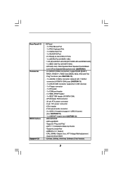
Support for CPU power (K10N78-1394) - FSB 2600 MHz (5.2 GT/s) (see CAUTION 5) - 1 x PCI Express 2.0 x16 slot (green @ x16 mode) - 2 x PCI Express x1 slots - 3 x PCI slots - capacity of system memory: 16GB (see ...
Support for CPU power (K10N78-1394) - FSB 2600 MHz (5.2 GT/s) (see CAUTION 5) - 1 x PCI Express 2.0 x16 slot (green @ x16 mode) - 2 x PCI Express x1 slots - 3 x PCI slots - capacity of system memory: 16GB (see ...
User Manual
Page 7
... (see CAUTION 10) - 1 x eSATAII 3.0Gb/s connector (shared with LED (ACT/LINK LED and SPEED LED) - 1 x IEEE 1394 Port (K10N78-1394) - HD Audio Jack: Side Speaker/Rear Speaker/Central/Bass/ Line in header - Rear Panel I/O Connector BIOS Feature Support CD I/O Panel ...1 x PS/2 Keyboard Port - 1 x VGA/D-Sub Port - 1 x VGA/DVI-D Port - 6 x Ready-to-Use USB 2.0 Ports - 1 x eSATAII Port (K10N78-1394) - 1 x RJ-45 LAN Port with 1 SATAII connector) (K10N78-1394) (see CAUTION 11) - 1 x ATA133 IDE connector (supports 2 x IDE devices) - 1 x Floppy connector - 1 x IR header - 1 x COM port header ...
... (see CAUTION 10) - 1 x eSATAII 3.0Gb/s connector (shared with LED (ACT/LINK LED and SPEED LED) - 1 x IEEE 1394 Port (K10N78-1394) - HD Audio Jack: Side Speaker/Rear Speaker/Central/Bass/ Line in header - Rear Panel I/O Connector BIOS Feature Support CD I/O Panel ...1 x PS/2 Keyboard Port - 1 x VGA/D-Sub Port - 1 x VGA/DVI-D Port - 6 x Ready-to-Use USB 2.0 Ports - 1 x eSATAII Port (K10N78-1394) - 1 x RJ-45 LAN Port with 1 SATAII connector) (K10N78-1394) (see CAUTION 11) - 1 x ATA133 IDE connector (supports 2 x IDE devices) - 1 x Floppy connector - 1 x IR header - 1 x COM port header ...

User Manual
Page 13
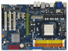
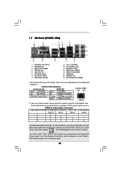
... 18 SATAII Connector (SATAII_3 (PORT2), Red) 36 eSATAII Connector (eSATAII_TOP, Orange) 19 NVIDIA GeForce 8200 Chipset 13 1.5 Motherboard Layout (K10N78-1394) 12 3 45 67 21.3cm (8.4-in) 1 PS2_USB_PW1 PS2 Mouse PS2 Keyboard AM2+ FSB2.6GHz DVI_CON1 VGA1 ATX12V1 DDRII_3 (64 bit...CPU_FAN1 140W CPU PCI Express 2.0 Super I/O PCIE2 PCIE3 RAID 1 FRONT_1394 HDMI_SPDIF1 1 AUDIO CODEC USB/WIFI HD_AUDIO1 CD1 1 IR1 1 FLOPPY1 PCIE1 K10N78-1394 CLRCMOS1 1 CMOS BATTERY SATAII_1 (PORT0) SATAII_3 (PORT2) SATAII_5 (PORT4) SATAII_2 (PORT1) SATAII_4 (PORT3) SATAII_6 (PORT5) PCI1 RoHS PCI2 ...
... 18 SATAII Connector (SATAII_3 (PORT2), Red) 36 eSATAII Connector (eSATAII_TOP, Orange) 19 NVIDIA GeForce 8200 Chipset 13 1.5 Motherboard Layout (K10N78-1394) 12 3 45 67 21.3cm (8.4-in) 1 PS2_USB_PW1 PS2 Mouse PS2 Keyboard AM2+ FSB2.6GHz DVI_CON1 VGA1 ATX12V1 DDRII_3 (64 bit...CPU_FAN1 140W CPU PCI Express 2.0 Super I/O PCIE2 PCIE3 RAID 1 FRONT_1394 HDMI_SPDIF1 1 AUDIO CODEC USB/WIFI HD_AUDIO1 CD1 1 IR1 1 FLOPPY1 PCIE1 K10N78-1394 CLRCMOS1 1 CMOS BATTERY SATAII_1 (PORT0) SATAII_3 (PORT2) SATAII_5 (PORT4) SATAII_2 (PORT1) SATAII_4 (PORT3) SATAII_6 (PORT5) PCI1 RoHS PCI2 ...
User Manual
Page 15
... will find "Mixer" tool on your computer, you are two LED next to the LAN port. 1.7 I/O Panel (K10N78-1394) 1 2 34 5 6 9 7 10 8 11 16 15 14 1 PS/2 Mouse Port (Green) 2 VGA/D-Sub Port 3 USB 2.0 Ports (USB45) 4 IEEE 1394 Port * 5 LAN RJ-45 Port 6 Side Speaker (Gray) 7 Rear Speaker (Black) 8 Central / Bass (Orange) 13 12...
... will find "Mixer" tool on your computer, you are two LED next to the LAN port. 1.7 I/O Panel (K10N78-1394) 1 2 34 5 6 9 7 10 8 11 16 15 14 1 PS/2 Mouse Port (Green) 2 VGA/D-Sub Port 3 USB 2.0 Ports (USB45) 4 IEEE 1394 Port * 5 LAN RJ-45 Port 6 Side Speaker (Gray) 7 Rear Speaker (Black) 8 Central / Bass (Orange) 13 12...

User Manual
Page 31
... (PORT5): see p.13/14, No. 23) Pin1 FLOPPY1 the red-striped side to the instruction of your IDE device vendor for internal storage devices. For K10N78-1394, SATAII_6 (PORT5) connector can be used for details about eSATAII and eSATAII installation procedures. 31 2.9 Onboard Headers and Connectors Onboard headers and connectors are NOT...
... (PORT5): see p.13/14, No. 23) Pin1 FLOPPY1 the red-striped side to the instruction of your IDE device vendor for internal storage devices. For K10N78-1394, SATAII_6 (PORT5) connector can be used for details about eSATAII and eSATAII installation procedures. 31 2.9 Onboard Headers and Connectors Onboard headers and connectors are NOT...

User Manual
Page 32
For K10N78-1394, you to the power connector on each drive. Then connect the white end of the power supply. Each USB 2.0 header can also be connected to support 2 USB 2.0 ports. This header can be used to support WiFi+AP function with ASRock WiFi-802. 11g or WiFi-802.11n module, an easy-to...
For K10N78-1394, you to the power connector on each drive. Then connect the white end of the power supply. Each USB 2.0 header can also be connected to support 2 USB 2.0 ports. This header can be used to support WiFi+AP function with ASRock WiFi-802. 11g or WiFi-802.11n module, an easy-to...

User Manual
Page 35
... Header (9-pin COM1) (see p.13 No.34 or p.14 No.33) IEEE 1394 Header (9-pin FRONT_1394) (see p.13/14, No. 2) 4 8 1 5 Please note that it is one IEEE 1394 header (FRONT_1394) on this motherboard. Besides one IEEE 1394 port. Though this motherboard provides 8-pin ATX 12V power connector, it can still work...use the 20-pin ATX power supply, please plug your power supply along with ATX 12V plug to this connector. This IEEE 1394 header can support one default IEEE 1394 port on the I/O panel, there is necessary to connect a power supply with Pin 1 and Pin 13. 20-Pin ATX...
... Header (9-pin COM1) (see p.13 No.34 or p.14 No.33) IEEE 1394 Header (9-pin FRONT_1394) (see p.13/14, No. 2) 4 8 1 5 Please note that it is one IEEE 1394 header (FRONT_1394) on this motherboard. Besides one IEEE 1394 port. Though this motherboard provides 8-pin ATX 12V power connector, it can still work...use the 20-pin ATX power supply, please plug your power supply along with ATX 12V plug to this connector. This IEEE 1394 header can support one default IEEE 1394 port on the I/O panel, there is necessary to connect a power supply with Pin 1 and Pin 13. 20-Pin ATX...
User Manual
Page 38
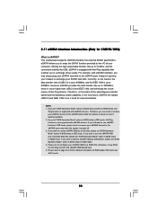
... may simply plug your eSATAII hard disk to the eSATAII ports instead of USB 2.0 is up to 480Mb/s, and for IEEE 1394 is eSATAII? 2.11 eSATAII Interface Introduction (Only for K10N78-1394) What is up to 400Mb/s. eSATAII is equipped with Hot Plug capability that eSATAII HDD should have. 5. If you to RAID...data disk, please set "SATA Operation Mode" option in the near future, eSATAII will replace USB 2.0 and IEEE 1394 to IDE mode, Hot Plug function is much higher than USB 2.0 and IEEE 1394, and still keeps the convenience of RAID mode, IDE mode and AHCI mode. 38 Please refer to page 46...
... may simply plug your eSATAII hard disk to the eSATAII ports instead of USB 2.0 is up to 480Mb/s, and for IEEE 1394 is eSATAII? 2.11 eSATAII Interface Introduction (Only for K10N78-1394) What is up to 400Mb/s. eSATAII is equipped with Hot Plug capability that eSATAII HDD should have. 5. If you to RAID...data disk, please set "SATA Operation Mode" option in the near future, eSATAII will replace USB 2.0 and IEEE 1394 to IDE mode, Hot Plug function is much higher than USB 2.0 and IEEE 1394, and still keeps the convenience of RAID mode, IDE mode and AHCI mode. 38 Please refer to page 46...

User Manual
Page 42
... of your chassis. STEP 4: Connect the other SATAII ports. 3. If you plan to use RAID 5 function, you need to the SATA / SATAII hard disk. 1. For K10N78-1394, it is used for internal storage devices. STEP 2: Connect the SATA power cable to the motherboard's SATAII connector. 2.13 Serial ATA (SATA) / Serial ATAII (SATAII...
... of your chassis. STEP 4: Connect the other SATAII ports. 3. If you plan to use RAID 5 function, you need to the SATA / SATAII hard disk. 1. For K10N78-1394, it is used for internal storage devices. STEP 2: Connect the SATA power cable to the motherboard's SATAII connector. 2.13 Serial ATA (SATA) / Serial ATAII (SATAII...

User Manual
Page 43
... SATA / SATAII HDDs are NOT set for RAID configuration, it is called "Hot Swap" for the action to exchange your SATAII hard disk. 43 For K10N78-1394, eSATAII is Hot Plug Function? However, please note that enables you may simply plug your eSATAII devices to the eSATAII ports instead of opening your...
... SATA / SATAII HDDs are NOT set for RAID configuration, it is called "Hot Swap" for the action to exchange your SATAII hard disk. 43 For K10N78-1394, eSATAII is Hot Plug Function? However, please note that enables you may simply plug your eSATAII devices to the eSATAII ports instead of opening your...
User Manual
Page 52
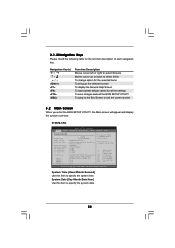
...exit the current screen 3.2 Main Screen When you enter the BIOS SETUP UTILITY, the Main screen will appear and display the system overview. K10N78-1394 BIOS SETUP UTILITY Main Smart Advanced H/W Monitor Boot Security Exit System Overview System Time System Date [14:00:09] [Fri 07/25/...2008] BIOS Version : K10N78-1394 P1.00 Processor Type : AMD Phenom (tm) 9750 Quad-Core Processor (64bit) Processor Speed : 2400MHz Microcode Update : 100F23/1000065 L1 Cache Size...
...exit the current screen 3.2 Main Screen When you enter the BIOS SETUP UTILITY, the Main screen will appear and display the system overview. K10N78-1394 BIOS SETUP UTILITY Main Smart Advanced H/W Monitor Boot Security Exit System Overview System Time System Date [14:00:09] [Fri 07/25/...2008] BIOS Version : K10N78-1394 P1.00 Processor Type : AMD Phenom (tm) 9750 Quad-Core Processor (64bit) Processor Speed : 2400MHz Microcode Update : 100F23/1000065 L1 Cache Size...
User Manual
Page 59
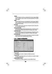
... [Auto]. MA Timing Use this to adjust values for CS/ODT Fine Delay feature. CS/ODT Fine Delay Use this to adjust values for K10N78-1394 only. Bank Interleaving Interleaving allows memory accesses to [31/64CLK]. Configuration options: [Auto], [1CLK], [2CLK] and [3CLK]. Use this to...on the same node, or accross nodes, decreasing access contention. 3.4.2 Chipset Configuration BIOS SETUP UTILITY Advanced Chipset Settings Onboard LAN Onboard 1394 Onboard HDMI HD Audio Onboard HD Audio Front Panel CD-In Hybrid SLI Share Memory Primary Graphics Adapter CPU - Onboard LAN This allows...
... [Auto]. MA Timing Use this to adjust values for CS/ODT Fine Delay feature. CS/ODT Fine Delay Use this to adjust values for K10N78-1394 only. Bank Interleaving Interleaving allows memory accesses to [31/64CLK]. Configuration options: [Auto], [1CLK], [2CLK] and [3CLK]. Use this to...on the same node, or accross nodes, decreasing access contention. 3.4.2 Chipset Configuration BIOS SETUP UTILITY Advanced Chipset Settings Onboard LAN Onboard 1394 Onboard HDMI HD Audio Onboard HD Audio Front Panel CD-In Hybrid SLI Share Memory Primary Graphics Adapter CPU - Onboard LAN This allows...
User Manual
Page 63
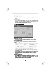
... the integrated IDE Controller. OnBoard IDE Controller Use this option to the configurations of this option to [Enabled] if you install SATA / SATAII device on K10N78-1394, please select [RAID] or [AHCI]. If you specify. ACPI HPET Table Use this item to enable eSATAII function on eSATAII port and plan to make...
... the integrated IDE Controller. OnBoard IDE Controller Use this option to the configurations of this option to [Enabled] if you install SATA / SATAII device on K10N78-1394, please select [RAID] or [AHCI]. If you specify. ACPI HPET Table Use this item to enable eSATAII function on eSATAII port and plan to make...
Quick Installation Guide
Page 1
...consequential damages (including damages for loss of profits, loss of business, loss of data, interruption of business and the like), even if ASRock has been advised of the possibility of such damages arising from any kind, either expressed or implied, including but not limited to the implied.... Products and corporate names appearing in the guide or product. Operation is subject to infringe. All rights reserved. 1 ASRock K10N78-1394 / K10N78 Motherboard English In no responsibility for informational use only and subject to change without intent to the following two conditions: ...
...consequential damages (including damages for loss of profits, loss of business, loss of data, interruption of business and the like), even if ASRock has been advised of the possibility of such damages arising from any kind, either expressed or implied, including but not limited to the implied.... Products and corporate names appearing in the guide or product. Operation is subject to infringe. All rights reserved. 1 ASRock K10N78-1394 / K10N78 Motherboard English In no responsibility for informational use only and subject to change without intent to the following two conditions: ...

Quick Installation Guide
Page 2
Motherboard Layout (K10N78-1394) English 1 PS2_USB_PW1 Jumper 20 System Panel Header (PANEL1, Orange) 2 ATX 12V Power Connector (ATX12V1) 21 Chassis... SATAII Connector (SATAII_5 (PORT4), Red) 29 HDMI_SPDIF Header (HDMI_SPDIF1, Yellow) 11 SATAII Connector (SATAII_6 (PORT5), Orange) 30 Front Panel IEEE 1394 Header 12 SATAII Connector (SATAII_4 (PORT3), Red) (FRONT_1394, Red) 13 SATAII Connector (SATAII_2 (PORT1), Red) 31 PCI Express x1 Slot ...SATAII_3 (PORT2), Red) 36 eSATAII Connector (eSATAII_TOP, Orange) 19 NVIDIA GeForce 8200 Chipset 2 ASRock K10N78-1394 / K10N78 Motherboard
Motherboard Layout (K10N78-1394) English 1 PS2_USB_PW1 Jumper 20 System Panel Header (PANEL1, Orange) 2 ATX 12V Power Connector (ATX12V1) 21 Chassis... SATAII Connector (SATAII_5 (PORT4), Red) 29 HDMI_SPDIF Header (HDMI_SPDIF1, Yellow) 11 SATAII Connector (SATAII_6 (PORT5), Orange) 30 Front Panel IEEE 1394 Header 12 SATAII Connector (SATAII_4 (PORT3), Red) (FRONT_1394, Red) 13 SATAII Connector (SATAII_2 (PORT1), Red) 31 PCI Express x1 Slot ...SATAII_3 (PORT2), Red) 36 eSATAII Connector (eSATAII_TOP, Orange) 19 NVIDIA GeForce 8200 Chipset 2 ASRock K10N78-1394 / K10N78 Motherboard

Quick Installation Guide
Page 3
Yellow) 7 2 x 240-pin DDR2 DIMM Slots (Dual Channel B: DDRII_3, DDRII_4; Motherboard Layout (K10N78) English 1 PS2_USB_PW1 Jumper 2 ATX 12V Power Connector (ATX12V1) 3 CPU Fan Connector (CPU_FAN1) 4 CPU Heatsink Retention Module 5 AM2 940-Pin CPU Socket 6 2 x 240-pin DDR2 DIMM ..., White) 31 PCI Express x1 Slot (PCIE2, White) 32 PCI Express x16 Slot (PCIE1, Green) 33 Serial Port Connector (COM1) 34 ATX Power Connector (ATXPWR1) 3 ASRock K10N78-1394 / K10N78 Motherboard
Yellow) 7 2 x 240-pin DDR2 DIMM Slots (Dual Channel B: DDRII_3, DDRII_4; Motherboard Layout (K10N78) English 1 PS2_USB_PW1 Jumper 2 ATX 12V Power Connector (ATX12V1) 3 CPU Fan Connector (CPU_FAN1) 4 CPU Heatsink Retention Module 5 AM2 940-Pin CPU Socket 6 2 x 240-pin DDR2 DIMM ..., White) 31 PCI Express x1 Slot (PCIE2, White) 32 PCI Express x16 Slot (PCIE1, Green) 33 Serial Port Connector (COM1) 34 ATX Power Connector (ATXPWR1) 3 ASRock K10N78-1394 / K10N78 Motherboard

Quick Installation Guide
Page 4
...TABLE for connection details in accordance with the type of speaker you use front panel audio. 4 ASRock K10N78-1394 / K10N78 Motherboard English Please refer to the table below for Audio Output Connection Audio Output Channels Front Speaker ...V -- -- 6 V V V -- 8 V V V V To enable Multi-Streaming function, you will find "Mixer" tool on your system. I/O Panel (K10N78-1394) 1 PS/2 Mouse Port (Green) 2 VGA/D-Sub Port 3 USB 2.0 Ports (USB45) 4 IEEE 1394 Port * 5 LAN RJ-45 Port 6 Side Speaker (Gray) 7 Rear Speaker (Black) 8 Central / Bass (Orange) 9 ** 10 11 12 13 14 ...
...TABLE for connection details in accordance with the type of speaker you use front panel audio. 4 ASRock K10N78-1394 / K10N78 Motherboard English Please refer to the table below for Audio Output Connection Audio Output Channels Front Speaker ...V -- -- 6 V V V -- 8 V V V V To enable Multi-Streaming function, you will find "Mixer" tool on your system. I/O Panel (K10N78-1394) 1 PS/2 Mouse Port (Green) 2 VGA/D-Sub Port 3 USB 2.0 Ports (USB45) 4 IEEE 1394 Port * 5 LAN RJ-45 Port 6 Side Speaker (Gray) 7 Rear Speaker (Black) 8 Central / Bass (Orange) 9 ** 10 11 12 13 14 ...