User Manual
Page 3
..., make sure that the total ampere rating of electrical current still flows. No disassembly NOTE: The warranty does not apply to products (including HDD, ODD, memory and warranty seal) that you follow all power, modem, and network cables from the power outlets before you leave plenty of attempting to disassemble/reassemble the system or modifying the hardware configuration. 3 Always unplug all instructions...
..., make sure that the total ampere rating of electrical current still flows. No disassembly NOTE: The warranty does not apply to products (including HDD, ODD, memory and warranty seal) that you follow all power, modem, and network cables from the power outlets before you leave plenty of attempting to disassemble/reassemble the system or modifying the hardware configuration. 3 Always unplug all instructions...
User Manual
Page 5
... 27 6.2.2 Installation 27 6.3 BADABOOMTM MEDIA CONVERTER (Trial version) ...... 31 6.4 CyberLink DVD Suite (Trial version, including PowerDVD, PowerDirector, etc 32 6.5 Symantec Norton AntiVirus Software (Trial version) .. 34 7 BIOS SETUP UTILITY 35 7.1 Introduction 35 7.1.1 BIOS Menu Bar 35 7.1.2 Navigation Keys 36 7.2 Main Screen 36 7.3 OC Tweaker Screen 37 7.4 Advanced Screen 39 7.4.1 CPU Configuration 40 7.4.2 Chipset Configuration 41 7.4.3 ACPI Configuration 42 7.4.4 SATA Configuration 43 7.4.5 USB Configuration 43 7.5 Fan Control 44 7.6 Boot Screen 44 7.6.1 Boot Settings...
... 27 6.2.2 Installation 27 6.3 BADABOOMTM MEDIA CONVERTER (Trial version) ...... 31 6.4 CyberLink DVD Suite (Trial version, including PowerDVD, PowerDirector, etc 32 6.5 Symantec Norton AntiVirus Software (Trial version) .. 34 7 BIOS SETUP UTILITY 35 7.1 Introduction 35 7.1.1 BIOS Menu Bar 35 7.1.2 Navigation Keys 36 7.2 Main Screen 36 7.3 OC Tweaker Screen 37 7.4 Advanced Screen 39 7.4.1 CPU Configuration 40 7.4.2 Chipset Configuration 41 7.4.3 ACPI Configuration 42 7.4.4 SATA Configuration 43 7.4.5 USB Configuration 43 7.5 Fan Control 44 7.6 Boot Screen 44 7.6.1 Boot Settings...
User Manual
Page 7
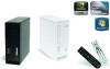
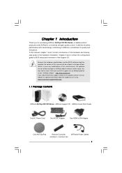
... 2 contain introduction of the Support CD. Because the hardware specifications and the BIOS software might be updated, the content of this manual will be subject to DVI Adapter One Anti-Slip Pad Remote Controller (ION330HT / ION330HT-BD) SATA and Power Cables 7 www.asrock.com/support/index.asp 1.1 Package Contents ASRock NetTop ION 330 Series ASRock Support CD ASRock Quick Start Guide One AC Power Cord One AC/DC Adapter One HDMI to change without further notice. In...
... 2 contain introduction of the Support CD. Because the hardware specifications and the BIOS software might be updated, the content of this manual will be subject to DVI Adapter One Anti-Slip Pad Remote Controller (ION330HT / ION330HT-BD) SATA and Power Cables 7 www.asrock.com/support/index.asp 1.1 Package Contents ASRock NetTop ION 330 Series ASRock Support CD ASRock Quick Start Guide One AC Power Cord One AC/DC Adapter One HDMI to change without further notice. In...
User Manual
Page 8
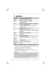
... VGA, 6xUSB 2.0, 1xS/PDIF, 1xPowered eSATA/USB **** HD Audio 7.1 channel with overclocking, including adjusting the setting in RAID / AHCI mode only. WARNING Please realize that there is a certain risk involved with DTS LAN Gigabit LAN WiFi 802.11b/g/n wireless LAN (ION 330HT / ION 330HT-BD) Remote Controller MCE Remote Controller (ION 330HT / ION 330HT-BD) Power Dimension 65W/19V Adapter 195mm(W)x70mm(H)x186m(L) Volume (liters) 2.5L Weight 1.75 Kg * Due to the CPU limitation, the actual memory...
... VGA, 6xUSB 2.0, 1xS/PDIF, 1xPowered eSATA/USB **** HD Audio 7.1 channel with overclocking, including adjusting the setting in RAID / AHCI mode only. WARNING Please realize that there is a certain risk involved with DTS LAN Gigabit LAN WiFi 802.11b/g/n wireless LAN (ION 330HT / ION 330HT-BD) Remote Controller MCE Remote Controller (ION 330HT / ION 330HT-BD) Power Dimension 65W/19V Adapter 195mm(W)x70mm(H)x186m(L) Volume (liters) 2.5L Weight 1.75 Kg * Due to the CPU limitation, the actual memory...
User Manual
Page 9
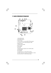
... SATA data cable 15. Infrared module header 8. ATX5V output power connector for slim ODD & 2.5" HDD 16. SATA connector: For HDD SATA data cable 9 1.3 System Motherboard Components 16 15 14 13 PCIE1 RoHS 1 2 3 AMCP7AION-HT EuP Ready DDRII_2 FSB800 DDRII_1 4 6 5 12 11 10 9 8 7 1. Northbridge heatsink 3. CPU heatsink 10. LPC header 14. SATA connector: For second HDD SATA data cable 5. Memory socket 7. J1 jumper: For second HDD SATA power cable 6. CMOS Battery 13. CPU fan 11. Fan connector 4. Fan connector 9. Mini-PCI Express expansion slot...
... SATA data cable 15. Infrared module header 8. ATX5V output power connector for slim ODD & 2.5" HDD 16. SATA connector: For HDD SATA data cable 9 1.3 System Motherboard Components 16 15 14 13 PCIE1 RoHS 1 2 3 AMCP7AION-HT EuP Ready DDRII_2 FSB800 DDRII_1 4 6 5 12 11 10 9 8 7 1. Northbridge heatsink 3. CPU heatsink 10. LPC header 14. SATA connector: For second HDD SATA data cable 5. Memory socket 7. J1 jumper: For second HDD SATA power cable 6. CMOS Battery 13. CPU fan 11. Fan connector 4. Fan connector 9. Mini-PCI Express expansion slot...
User Manual
Page 10
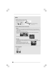
... in a 30 60 angle. Disassembly 1.Lift the DIMM slot hook sideways using the slot as axis. SATA and Power Connections SATA & Power Connections Connect to ODD HDD ODD Connect to HDD Connect to SATA Connector (14) Connect to ATX5V Power Connector (15) Connect to put your both sides of the DIMM are in place. When doing this, make sure to SATA Connector (16) 2. NOTE. 1. A hock clicking sound denotes that the memory module is in place. 2.Insert...
... in a 30 60 angle. Disassembly 1.Lift the DIMM slot hook sideways using the slot as axis. SATA and Power Connections SATA & Power Connections Connect to ODD HDD ODD Connect to HDD Connect to SATA Connector (14) Connect to ATX5V Power Connector (15) Connect to put your both sides of the DIMM are in place. When doing this, make sure to SATA Connector (16) 2. NOTE. 1. A hock clicking sound denotes that the memory module is in place. 2.Insert...
User Manual
Page 13
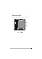
1.6 Internal System Components Optical disc & Hard disk drives The optical disc and hard disc drives are mounted in a drive cage. Optical Disc Drive 34. Hard Disc Drive 13 The cage can be removed by removing the top screws. 34 32 33 32. System Cooling Fan 33.
1.6 Internal System Components Optical disc & Hard disk drives The optical disc and hard disc drives are mounted in a drive cage. Optical Disc Drive 34. Hard Disc Drive 13 The cage can be removed by removing the top screws. 34 32 33 32. System Cooling Fan 33.

User Manual
Page 16
5. Connecting Stereo Speakers or Headphones (Front L/R Out Port) 8. Connecting External Audio Device (Line In Port for 8 Channel) 7. Connecting eSATA / USB Device (Powered eSATA/USB Port) or 6. Connecting Microphone (Mic In Port) 16 Rear Port for 2/4/6 Channel;
5. Connecting Stereo Speakers or Headphones (Front L/R Out Port) 8. Connecting External Audio Device (Line In Port for 8 Channel) 7. Connecting eSATA / USB Device (Powered eSATA/USB Port) or 6. Connecting Microphone (Mic In Port) 16 Rear Port for 2/4/6 Channel;
User Manual
Page 23
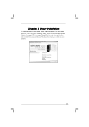
Chapter 5 Driver Installation To install the drivers to your system, please insert the support CD to your system can work properly. 23 Therefore, the drivers you install can be auto-detected and listed on the support CD driver page. Then, the drivers compatible to install those required drivers. Please follow the order from up to bottom side to your optical drive first.
Chapter 5 Driver Installation To install the drivers to your system, please insert the support CD to your system can work properly. 23 Therefore, the drivers you install can be auto-detected and listed on the support CD driver page. Then, the drivers compatible to install those required drivers. Please follow the order from up to bottom side to your optical drive first.
User Manual
Page 25
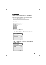
... follow the instructions on Instant Boot setup page. You may choose a different folder if you need , and click "Next". a. b. c. Select the start menu folder. A. Select destination location. Install Instant Boot driver from ASRock support CD, or you install Instant Boot. You may choose a different folder if you need , and click "Next". 25 Click "Next" to get the latest utility and BIOS: http://www.asrock.com/feature/InstantBoot/download.asp...
... follow the instructions on Instant Boot setup page. You may choose a different folder if you need , and click "Next". a. b. c. Select the start menu folder. A. Select destination location. Install Instant Boot driver from ASRock support CD, or you install Instant Boot. You may choose a different folder if you need , and click "Next". 25 Click "Next" to get the latest utility and BIOS: http://www.asrock.com/feature/InstantBoot/download.asp...
User Manual
Page 26
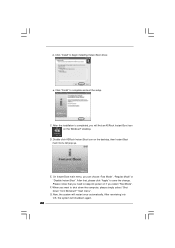
... simply select "Shut Down" from Windows® "Start menu". After reentering into OS, the system will restart once automatically. When you select "Fast Mode". Now, the system will shutdown again. 26 E. e. After that you can choose "Fast Mode", "Regular Mode" or "Disable Instant Boot". On Instant Boot main menu, you need to begin installing Instant Boot driver. D. F. G. Click "Install" to keep AC power on the Windows® desktop. d.
... simply select "Shut Down" from Windows® "Start menu". After reentering into OS, the system will restart once automatically. When you select "Fast Mode". Now, the system will shutdown again. 26 E. e. After that you can choose "Fast Mode", "Regular Mode" or "Disable Instant Boot". On Instant Boot main menu, you need to begin installing Instant Boot driver. D. F. G. Click "Install" to keep AC power on the Windows® desktop. d.
User Manual
Page 39
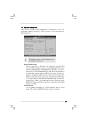
...Flash ROM. BIOS SETUP UTILITY Main OC Tweaker Advanced Fan Control Boot Security Exit Advanced Settings Options for the following items: CPU Configuration, Chipset Configuration, ACPI Configuration, SATA Configuration and USB Configuration. Good Night LED Use this tool and save the new BIOS file to your USB flash drive, floppy disk or hard drive, then you execute ASRock Instant Flash utility, the utility will show the BIOS files and their respective information. Enable this section may cause system to malfunction. ASRock Instant Flash ASRock Instant Flash is a BIOS flash utility...
...Flash ROM. BIOS SETUP UTILITY Main OC Tweaker Advanced Fan Control Boot Security Exit Advanced Settings Options for the following items: CPU Configuration, Chipset Configuration, ACPI Configuration, SATA Configuration and USB Configuration. Good Night LED Use this tool and save the new BIOS file to your USB flash drive, floppy disk or hard drive, then you execute ASRock Instant Flash utility, the utility will show the BIOS files and their respective information. Enable this section may cause system to malfunction. ASRock Instant Flash ASRock Instant Flash is a BIOS flash utility...

User Manual
Page 44
... Boot Settings Configuration Configure Settings during System Boot. 1st Boot Device 2nd Boot Device Hard Disk Drives CD/DVD Drives [HDD: PM - Configuration options: [Auto], [UltraSilent Level 1], [Silent 2], [Normal 3], [Performance 4] and [Full Speed 5]. 7.6 Boot Screen In this section, it will be better. ROM C] Select Screen Select Item Enter Go to control the fan mode. 7.5 Fan Control In this section, it allows you get higher. HDS722580VL] [CD / DVD: 3S - BIOS SETUP UTILITY Main OC Tweaker Advanced H/W Monitor Boot Security Exit Hardware Health Event Monitoring CPU...
... Boot Settings Configuration Configure Settings during System Boot. 1st Boot Device 2nd Boot Device Hard Disk Drives CD/DVD Drives [HDD: PM - Configuration options: [Auto], [UltraSilent Level 1], [Silent 2], [Normal 3], [Performance 4] and [Full Speed 5]. 7.6 Boot Screen In this section, it will be better. ROM C] Select Screen Select Item Enter Go to control the fan mode. 7.5 Fan Control In this section, it allows you get higher. HDS722580VL] [CD / DVD: 3S - BIOS SETUP UTILITY Main OC Tweaker Advanced H/W Monitor Boot Security Exit Hardware Health Event Monitoring CPU...
User Manual
Page 46
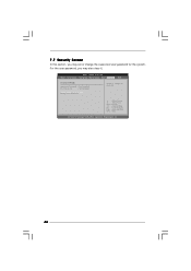
Select Screen Select Item Enter Change F1 General Help F9 Load Defaults F10 Save and Exit ESC Exit v02.54 (C) Copyright 1985-2005, American Megatrends, Inc. 46 BIOS SETUP UTILITY Main OC Tweaker Advanced Fan Control Boot Security Exit Security Settings Supervisor Password : Not Installed User Password : Not Installed Change Supervisor Password Change User Password Install or Change the password. 7.7 Security Screen In this section, you may set or change the supervisor/user password for the system. For the user password, you may also clear it.
Select Screen Select Item Enter Change F1 General Help F9 Load Defaults F10 Save and Exit ESC Exit v02.54 (C) Copyright 1985-2005, American Megatrends, Inc. 46 BIOS SETUP UTILITY Main OC Tweaker Advanced Fan Control Boot Security Exit Security Settings Supervisor Password : Not Installed User Password : Not Installed Change Supervisor Password Change User Password Install or Change the password. 7.7 Security Screen In this section, you may set or change the supervisor/user password for the system. For the user password, you may also clear it.
User Manual
Page 48
... on a specific item then follow the installation wizard to install it. 8.2.4 Contact Information If you may contact your CD-ROM drive. or you need to contact ASRock or want to visit ASRock's website at http://www.asrock.com; Please install the necessary drivers to activate the devices. 8.2.3 Utilities Menu The Utilities Menu shows the applications software that enhance the system features. 8.2.1 Running The Support CD To begin using the support CD...
... on a specific item then follow the installation wizard to install it. 8.2.4 Contact Information If you may contact your CD-ROM drive. or you need to contact ASRock or want to visit ASRock's website at http://www.asrock.com; Please install the necessary drivers to activate the devices. 8.2.3 Utilities Menu The Utilities Menu shows the applications software that enhance the system features. 8.2.1 Running The Support CD To begin using the support CD...
RAID Installation Guide
Page 2
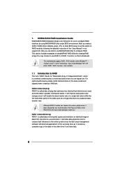
... drive if one logical unit. After you make a SATA / SATAII driver diskette, press to enter BIOS setup to set . This motherboard supports RAID / AHCI function under BIOS environment. Hot-Plug any fault tolerance. 1. RAID 0 (Data Striping) RAID 0 is called data striping that copies and maintains an identical image of a single disk alone while the two hard disks perform the same work as it does not provide any HDDs of the same model...
... drive if one logical unit. After you make a SATA / SATAII driver diskette, press to enter BIOS setup to set . This motherboard supports RAID / AHCI function under BIOS environment. Hot-Plug any fault tolerance. 1. RAID 0 (Data Striping) RAID 0 is called data striping that copies and maintains an identical image of a single disk alone while the two hard disks perform the same work as it does not provide any HDDs of the same model...

RAID Installation Guide
Page 4
BIOS SETUP UTILITY Advanced SATA Configuration Onboard SATA Controller SATA Operation Mode SATAII_1 SATAII_2 SATAII_3 ESATA [Enabled] [RAID] [ATAPI CDROM] [Hard Disk] [Not Detected] [Not Detected] Options Enabled Disabled +F1 F9 F10 ESC Select Screen Select Item Change Option General Help Load Defaults Save and Exit Exit v02.54 (C) Copyright 1985-2005, American Megatrends, Inc. Define a New Array window appears. The RAID prompt appears as RAID array disk, the operation procedures are the drives that you enabled from the RAID Configuration BIOS setup page...
BIOS SETUP UTILITY Advanced SATA Configuration Onboard SATA Controller SATA Operation Mode SATAII_1 SATAII_2 SATAII_3 ESATA [Enabled] [RAID] [ATAPI CDROM] [Hard Disk] [Not Detected] [Not Detected] Options Enabled Disabled +F1 F9 F10 ESC Select Screen Select Item Change Option General Help Load Defaults Save and Exit Exit v02.54 (C) Copyright 1985-2005, American Megatrends, Inc. Define a New Array window appears. The RAID prompt appears as RAID array disk, the operation procedures are the drives that you enabled from the RAID Configuration BIOS setup page...
RAID Installation Guide
Page 7
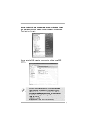
... 64bit OS) For Windows® 7 / 7 64-bit, there is able to load the RAID driver and install it in RAID mode, please copy the RAID driver from our support CD to use RAID function. Click "All Programs", "NVIDIA Corporation", "NVIDIA Control Panel", and then "Storage". You can review the RAID arrays that you have set up and start to your system is no such limitation. 7 Therefore, your USB flash.
... 64bit OS) For Windows® 7 / 7 64-bit, there is able to load the RAID driver and install it in RAID mode, please copy the RAID driver from our support CD to use RAID function. Click "All Programs", "NVIDIA Corporation", "NVIDIA Control Panel", and then "Storage". You can review the RAID arrays that you have set up and start to your system is no such limitation. 7 Therefore, your USB flash.
RAID Installation Guide
Page 10
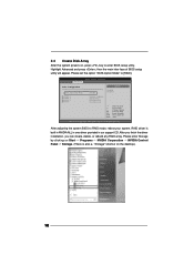
... the driver installation, you can create, delete, or rebuild any RAID array. RAID driver is also a "Storage" shortcut on , press key to enter BIOS setup utility. Highlight Advanced and press , then the main inter-face of BIOS setup utility will appear. BIOS SETUP UTILITY Advanced SATA Configuration Onboard SATA Controller SATA Operation Mode SATAII_1 SATAII_2 SATAII_3 ESATA [Enabled] [RAID] [ATAPI CDROM] [Hard Disk] [Not Detected] [Not Detected] Options Enabled Disabled +F1 F9 F10 ESC Select Screen Select Item Change Option General Help Load Defaults...
... the driver installation, you can create, delete, or rebuild any RAID array. RAID driver is also a "Storage" shortcut on , press key to enter BIOS setup utility. Highlight Advanced and press , then the main inter-face of BIOS setup utility will appear. BIOS SETUP UTILITY Advanced SATA Configuration Onboard SATA Controller SATA Operation Mode SATAII_1 SATAII_2 SATAII_3 ESATA [Enabled] [RAID] [ATAPI CDROM] [Hard Disk] [Not Detected] [Not Detected] Options Enabled Disabled +F1 F9 F10 ESC Select Screen Select Item Change Option General Help Load Defaults...
RAID Installation Guide
Page 15
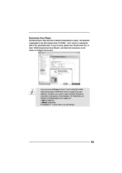
... USB flash. For RAID1, "sync" results in the following path of our support CD: \..i386 (for 32bit OS) \..AMD64 (for 64bit OS) For Windows® 7 / 7 64-bit, there is no such limitation. 15 The operation is able to load the RAID driver and install it in RAID mode, please copy the RAID driver from our support CD to the redundancy disk. The RAID drivers are located in...
... USB flash. For RAID1, "sync" results in the following path of our support CD: \..i386 (for 32bit OS) \..AMD64 (for 64bit OS) For Windows® 7 / 7 64-bit, there is no such limitation. 15 The operation is able to load the RAID driver and install it in RAID mode, please copy the RAID driver from our support CD to the redundancy disk. The RAID drivers are located in...

