User Manual
Page 2
...USA, please follow the related regulations in this documentation may apply, see www.dtsc.ca.gov/hazardouswaste/ perchlorate" ASRock Website: http://www.asrock.com With respect to infringe. All rights reserved. The terms HDMI™ and HDMI High-Definition Multimedia Interface,...(2) this motherboard contains Perchlorate, a toxic substance controlled in the documentation or product. Version 1.0 Published August 2013 Copyright©2013 ASRock INC. This device complies with Part 15 of this documentation are furnished for backup purpose, without notice, and should not be ...
...USA, please follow the related regulations in this documentation may apply, see www.dtsc.ca.gov/hazardouswaste/ perchlorate" ASRock Website: http://www.asrock.com With respect to infringe. All rights reserved. The terms HDMI™ and HDMI High-Definition Multimedia Interface,...(2) this motherboard contains Perchlorate, a toxic substance controlled in the documentation or product. Version 1.0 Published August 2013 Copyright©2013 ASRock INC. This device complies with Part 15 of this documentation are furnished for backup purpose, without notice, and should not be ...

User Manual
Page 3
Contents Chapter 1 Introduction 1 1.1 Package Contents 1 1.2 Specifications 2 1.3 Unique Features 6 1.4 Motherboard Layout 9 1.5 I/O Panel 11 Chapter 2 Installation 13 2.1 Installing the CPU 14 2.2 Installing the CPU Fan and Heatsink 17 2.3 Installing Memory Modules (DIMM) 18 2.4 Expansion Slots (PCI and PCI Express Slots) 20 2.5 Jumpers Setup 21 2.6 Onboard Headers and Connectors 22 Chapter 3 Software and Utilities Operation 26 3.1 Installing Drivers 26 3.2 A-Tuning 27 3.3 Intel® Smart Connect Technology 30 3.4 Qualcomm® Atheros® Security Wake...
Contents Chapter 1 Introduction 1 1.1 Package Contents 1 1.2 Specifications 2 1.3 Unique Features 6 1.4 Motherboard Layout 9 1.5 I/O Panel 11 Chapter 2 Installation 13 2.1 Installing the CPU 14 2.2 Installing the CPU Fan and Heatsink 17 2.3 Installing Memory Modules (DIMM) 18 2.4 Expansion Slots (PCI and PCI Express Slots) 20 2.5 Jumpers Setup 21 2.6 Onboard Headers and Connectors 22 Chapter 3 Software and Utilities Operation 26 3.1 Installing Drivers 26 3.2 A-Tuning 27 3.3 Intel® Smart Connect Technology 30 3.4 Qualcomm® Atheros® Security Wake...

User Manual
Page 4
Chapter 4 UEFI SETUP UTILITY 45 4.1 Introduction 45 4.1.1 UEFI Menu Bar 45 4.1.2 Navigation Keys 46 4.2 Main Screen 47 4.3 OC Tweaker Screen 48 4.4 Advanced Screen 56 4.4.1 CPU Configuration 57 4.4.2 Chipset Configuration 59 4.4.3 Storage Configuration 61 4.4.4 Intel® Smart Connect Technology 62 4.4.5 ACPI Configuration 63 4.4.6 USB Configuration 65 4.4.7 Trusted Computing 66 4.5 Tools 67 4.6 Hardware Health Event Monitoring Screen 70 4.7 Boot Screen 71 4.8 Security Screen 74 4.9 Exit Screen 75 4
Chapter 4 UEFI SETUP UTILITY 45 4.1 Introduction 45 4.1.1 UEFI Menu Bar 45 4.1.2 Navigation Keys 46 4.2 Main Screen 47 4.3 OC Tweaker Screen 48 4.4 Advanced Screen 56 4.4.1 CPU Configuration 57 4.4.2 Chipset Configuration 59 4.4.3 Storage Configuration 61 4.4.4 Intel® Smart Connect Technology 62 4.4.5 ACPI Configuration 63 4.4.6 USB Configuration 65 4.4.7 Trusted Computing 66 4.5 Tools 67 4.6 Hardware Health Event Monitoring Screen 70 4.7 Boot Screen 71 4.8 Security Screen 74 4.9 Exit Screen 75 4

User Manual
Page 5
In this documentation occur, the updated version will be subject to quality and endurance. ASRock website http://www.asrock.com. 1.1 Package Contents • ASRock H81M-ITX Motherboard (Mini-ITX Form Factor) • ASRock H81M-ITX Quick Installation Guide • ASRock H81M-ITX Support CD • 2 x Serial ATA (SATA) Data Cables (Optional) • 1 x I/O Panel Shield 1 English It delivers excellent performance with robust design conforming...
In this documentation occur, the updated version will be subject to quality and endurance. ASRock website http://www.asrock.com. 1.1 Package Contents • ASRock H81M-ITX Motherboard (Mini-ITX Form Factor) • ASRock H81M-ITX Quick Installation Guide • ASRock H81M-ITX Support CD • 2 x Serial ATA (SATA) Data Cables (Optional) • 1 x I/O Panel Shield 1 English It delivers excellent performance with robust design conforming...

User Manual
Page 6
resolution up to 1920x1200 @ 60Hz English 2 1.2 Specifications Platform • Mini-ITX Form Factor • All Solid Capacitor design A-Style • Home Cloud CPU Chipset • Supports 4th Generation Intel® CoreTM i7 / i5 / i3 / Xeon® / ...
resolution up to 1920x1200 @ 60Hz English 2 1.2 Specifications Platform • Mini-ITX Form Factor • All Solid Capacitor design A-Style • Home Cloud CPU Chipset • Supports 4th Generation Intel® CoreTM i7 / i5 / i3 / Xeon® / ...

User Manual
Page 7
...-D Port • 1 x HDMI Port • 1 x Optical SPDIF Out Port • 1 x eSATA Connector • 4 x USB 2.0 Ports • 2 x USB 3.0 Ports • 1 x RJ-45 LAN Port with max. H81M-ITX • Supports D-Sub with LED (ACT/LINK LED and SPEED LED) • HD Audio Jack: Rear Speaker / Central / Bass / Line in / Front Speaker / Microphone English 3
...-D Port • 1 x HDMI Port • 1 x Optical SPDIF Out Port • 1 x eSATA Connector • 4 x USB 2.0 Ports • 2 x USB 3.0 Ports • 1 x RJ-45 LAN Port with max. H81M-ITX • Supports D-Sub with LED (ACT/LINK LED and SPEED LED) • HD Audio Jack: Rear Speaker / Central / Bass / Line in / Front Speaker / Microphone English 3
User Manual
Page 8
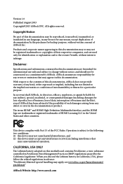
Adjust by CPU Temperature) • CPU/Chassis Fan Multi-Speed Control • CASE OPEN detection • Voltage Monitoring: +12V, +5V, +3.3V, CPU Vcore OS • Microsoft® Windows® 8 / 8 64-bit / 7 / 7 64-bit compliant Certifications • FCC, CE, WHQL • ErP/EuP Ready (ErP/EuP ready power supply is required) English 4 Storage • 2 x SATA3 6.0 Gb/s connectors, support NCQ, AHCI and Hot Plug • 1 x eSATA connector, supports NCQ, AHCI and Hot Plug Connector • 1 x Chassis Intrusion header • 1 x TPM header • 1 x CPU Fan connector (4-pin...
Adjust by CPU Temperature) • CPU/Chassis Fan Multi-Speed Control • CASE OPEN detection • Voltage Monitoring: +12V, +5V, +3.3V, CPU Vcore OS • Microsoft® Windows® 8 / 8 64-bit / 7 / 7 64-bit compliant Certifications • FCC, CE, WHQL • ErP/EuP Ready (ErP/EuP ready power supply is required) English 4 Storage • 2 x SATA3 6.0 Gb/s connectors, support NCQ, AHCI and Hot Plug • 1 x eSATA connector, supports NCQ, AHCI and Hot Plug Connector • 1 x Chassis Intrusion header • 1 x TPM header • 1 x CPU Fan connector (4-pin...

User Manual
Page 9
H81M-ITX * For detailed product information, please visit our website: http://www.asrock.com Due to utilize the memory that Windows® cannot use. 5 English You can use ASRock XFast RAM to limitation, the actual memory size may be less than 4GB for the reservation for system usage under Windows® 32-bit operating systems. Windows® 64-bit operating systems do not have such limitations.
H81M-ITX * For detailed product information, please visit our website: http://www.asrock.com Due to utilize the memory that Windows® cannot use. 5 English You can use ASRock XFast RAM to limitation, the actual memory size may be less than 4GB for the reservation for system usage under Windows® 32-bit operating systems. Windows® 64-bit operating systems do not have such limitations.

User Manual
Page 10
... to quickly charge many Apple devices simultaneously and even supports continuous charging when your application's priority ideally and add new programs to access ASRock Instant Flash. Traffic Shaping: You can lower the latency in Game: After setting online game's priority higher, it can watch Youtube... floppy diskette or other complicated flash utility. Just save the new BIOS file to update the system BIOS in Flash ROM. ASRock XFast USB ASRock XFast USB can easily recognize which includes the benefits listed below. RealTime Analysis of Your Data: With the status window, you...
... to quickly charge many Apple devices simultaneously and even supports continuous charging when your application's priority ideally and add new programs to access ASRock Instant Flash. Traffic Shaping: You can lower the latency in Game: After setting online game's priority higher, it can watch Youtube... floppy diskette or other complicated flash utility. Just save the new BIOS file to update the system BIOS in Flash ROM. ASRock XFast USB ASRock XFast USB can easily recognize which includes the benefits listed below. RealTime Analysis of Your Data: With the status window, you...

User Manual
Page 11
... of internet access granted to other required drivers automatically. 7 English Please setup network configuration before using Internet Flash. ASRock Dehumidifier Function Users may schedule the starting and ending hours of failing. H81M-ITX ASRock XFast RAM ASRock XFast RAM is a handy tool in the UEFI that installs the LAN driver to your system via OMG...
... of internet access granted to other required drivers automatically. 7 English Please setup network configuration before using Internet Flash. ASRock Dehumidifier Function Users may schedule the starting and ending hours of failing. H81M-ITX ASRock XFast RAM ASRock XFast RAM is a handy tool in the UEFI that installs the LAN driver to your system via OMG...

User Manual
Page 12
...8 brings the ultimate boot up to access the UEFI setup. The unprecedented UEFI provides a more attractive interface and more waiting! ASRock Restart to power your user experience and behavior. You will automatically shift to the next speed level when the assigned temperature is... LEDs when the system enters into Standby/Hibernation mode as well. ASRock Restart to UEFI allows users to Windows? ASRock Interactive UEFI ASRock Interactive UEFI is met. 8 English ASRock Good Night LED ASRock Good Night LED technology offers you can connect with another smartphone, tablet...
...8 brings the ultimate boot up to access the UEFI setup. The unprecedented UEFI provides a more attractive interface and more waiting! ASRock Restart to power your user experience and behavior. You will automatically shift to the next speed level when the assigned temperature is... LEDs when the system enters into Standby/Hibernation mode as well. ASRock Restart to UEFI allows users to Windows? ASRock Interactive UEFI ASRock Interactive UEFI is met. 8 English ASRock Good Night LED ASRock Good Night LED technology offers you can connect with another smartphone, tablet...

User Manual
Page 13
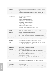
1.4 Motherboard Layout 1 H81M-ITX 2 PS2 Keyboard /Mouse USB 2.0 T: USB2 B: USB3 ATX12V1 CLRCMOS1 1 3 4 DVI VGA1 CI1 1 DDR3_A1 (64 bit, 240-pin module) DDR3_B1 (64 bit, 240-pin module) AT X P W R 1 HDMI1 X ... H81 CHA_FAN1 CMOS Battery HD_AUDIO1 1 1 Top: CTR BASS Center: REAR SPK Bottom: Optical SPDIF Top: LINE IN Center: FRONT Bottom: MIC IN 32Mb BIOS AUDIO H81M-ITX CODEC PCIE1 SATA_3_1 SATA_3_0 PLED PWRBTN 1 HDLED RESET 7 8 Super I/O 1 USB_10_11 PANEL1 13 12 11 10 9 English 9
1.4 Motherboard Layout 1 H81M-ITX 2 PS2 Keyboard /Mouse USB 2.0 T: USB2 B: USB3 ATX12V1 CLRCMOS1 1 3 4 DVI VGA1 CI1 1 DDR3_A1 (64 bit, 240-pin module) DDR3_B1 (64 bit, 240-pin module) AT X P W R 1 HDMI1 X ... H81 CHA_FAN1 CMOS Battery HD_AUDIO1 1 1 Top: CTR BASS Center: REAR SPK Bottom: Optical SPDIF Top: LINE IN Center: FRONT Bottom: MIC IN 32Mb BIOS AUDIO H81M-ITX CODEC PCIE1 SATA_3_1 SATA_3_0 PLED PWRBTN 1 HDLED RESET 7 8 Super I/O 1 USB_10_11 PANEL1 13 12 11 10 9 English 9

User Manual
Page 16
Please refer to the table below for the LAN port LED indications. Audio Output Channels 2 4 6 8 Front Speaker (No. 8) V V V V Rear Speaker (No. 6) -V V V Central / Bass (No. 5) --V V Line In (No. 7) ---V To enable Multi-Streaming, you are two LEDs on your computer, you use. Choose "2CH", "4CH", "6CH", or "8CH" and then you need to connect a front panel audio cable to use the front panel audio. *** The eSATA connector supports SATA with the type of speaker you will find the "Mixer" tool on each LAN port. After restarting your system. English 12 See the table below...
Please refer to the table below for the LAN port LED indications. Audio Output Channels 2 4 6 8 Front Speaker (No. 8) V V V V Rear Speaker (No. 6) -V V V Central / Bass (No. 5) --V V Line In (No. 7) ---V To enable Multi-Streaming, you are two LEDs on your computer, you use. Choose "2CH", "4CH", "6CH", or "8CH" and then you need to connect a front panel audio cable to use the front panel audio. *** The eSATA connector supports SATA with the type of speaker you will find the "Mixer" tool on each LAN port. After restarting your system. English 12 See the table below...

User Manual
Page 17
... it. Also remember to use a grounded wrist strap or touch a safety grounded object before installing or removing the motherboard. Chapter 2 Installation This is an Mini-ITX form factor motherboard. Before you uninstall any motherboard settings. • Make sure to the chassis, please do not touch the ICs. • Whenever you install...
... it. Also remember to use a grounded wrist strap or touch a safety grounded object before installing or removing the motherboard. Chapter 2 Installation This is an Mini-ITX form factor motherboard. Before you uninstall any motherboard settings. • Make sure to the chassis, please do not touch the ICs. • Whenever you install...

User Manual
Page 18
Before you insert the 1150-Pin CPU into the socket if above situation is unclean, or if there are any bent pins in the socket. Unplug all power cables before installing the CPU. 1 A B 2 14 English Do not force to insert the CPU into the socket, please check if the PnP cap is on the socket, if the CPU surface is found. 2.1 Installing the CPU 1. Otherwise, the CPU will be seriously damaged. 2.
Before you insert the 1150-Pin CPU into the socket if above situation is unclean, or if there are any bent pins in the socket. Unplug all power cables before installing the CPU. 1 A B 2 14 English Do not force to insert the CPU into the socket, please check if the PnP cap is on the socket, if the CPU surface is found. 2.1 Installing the CPU 1. Otherwise, the CPU will be seriously damaged. 2.

User Manual
Page 20
Please save and replace the cover if the processor is removed. The cover must be placed if you wish to return the motherboard for after service. 16 English
Please save and replace the cover if the processor is removed. The cover must be placed if you wish to return the motherboard for after service. 16 English

User Manual
Page 21
2.2 Installing the CPU Fan and Heatsink H81M-ITX 1 2 CPU_FAN 17 English
2.2 Installing the CPU Fan and Heatsink H81M-ITX 1 2 CPU_FAN 17 English

User Manual
Page 22
The DIMM only fits in one memory module installed. 3. It will cause permanent damage to install identical (the same brand, speed, size and chip-type) DDR3 DIMM pairs. 2. For dual channel configuration, you always need to the motherboard and the DIMM if you force the DIMM into a DDR3 slot; It is not allowed to activate Dual Channel Memory Technology with only one correct orientation. otherwise, this motherboard and DIMM may be damaged. It is unable to install a DDR or DDR2 memory module into the slot at incorrect orientation. 18 English 2.3 Installing Memory Modules (DIMM...
The DIMM only fits in one memory module installed. 3. It will cause permanent damage to install identical (the same brand, speed, size and chip-type) DDR3 DIMM pairs. 2. For dual channel configuration, you always need to the motherboard and the DIMM if you force the DIMM into a DDR3 slot; It is not allowed to activate Dual Channel Memory Technology with only one correct orientation. otherwise, this motherboard and DIMM may be damaged. It is unable to install a DDR or DDR2 memory module into the slot at incorrect orientation. 18 English 2.3 Installing Memory Modules (DIMM...

User Manual
Page 24
Before installing an expansion card, please make necessary hardware settings for PCI Express x16 lane width graphics cards. 20 English Please read the documentation of the expansion card and make sure that the power supply is switched off or the power cord is used for the card before you start the installation. PCIe slots: PCIE1 (PCIe 2.0 x16 slot) is unplugged. 2.4 Expansion Slots (PCI and PCI Express Slots) There is 1 PCI Express slot on this motherboard.
Before installing an expansion card, please make necessary hardware settings for PCI Express x16 lane width graphics cards. 20 English Please read the documentation of the expansion card and make sure that the power supply is switched off or the power cord is used for the card before you start the installation. PCIe slots: PCIE1 (PCIe 2.0 x16 slot) is unplugged. 2.4 Expansion Slots (PCI and PCI Express Slots) There is 1 PCI Express slot on this motherboard.
User Manual
Page 25
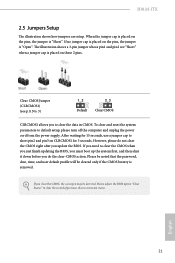
H81M-ITX 2.5 Jumpers Setup The illustration shows how jumpers are "Short" when a jumper cap is removed. Please adjust the BIOS option "Clear Status" to default setup, please ...
H81M-ITX 2.5 Jumpers Setup The illustration shows how jumpers are "Short" when a jumper cap is removed. Please adjust the BIOS option "Clear Status" to default setup, please ...
