
Intel Rapid Storage Guide
Page 12
... Advanced menu. 3. Select 1: Create RAID Volume and press Enter. 3. Click the Storage Configuration menu. 4. Enable RAID in System BIOS Use the instructions included with your motherboard to enable RAID in the system BIOS, a RAID volume must be created, and the F6 installation method must be used to load the Intel®...
... Advanced menu. 3. Select 1: Create RAID Volume and press Enter. 3. Click the Storage Configuration menu. 4. Enable RAID in System BIOS Use the instructions included with your motherboard to enable RAID in the system BIOS, a RAID volume must be created, and the F6 installation method must be used to load the Intel®...

User Manual
Page 2
..., special, incidental, or consequential damages (including damages for a particular purpose. With respect to the contents of this manual, ASRock does not provide warranty of any kind, either expressed or implied, including but not limited to infringe. "Perchlorate Material-special ..., in any form or by any interference received, including interference that may appear in this motherboard contains Perchlorate, a toxic substance controlled in advance. ASRock assumes no event shall ASRock, its directors, of cers, employees, or agents be registered trademarks or copyrights of their...
..., special, incidental, or consequential damages (including damages for a particular purpose. With respect to the contents of this manual, ASRock does not provide warranty of any kind, either expressed or implied, including but not limited to infringe. "Perchlorate Material-special ..., in any form or by any interference received, including interference that may appear in this motherboard contains Perchlorate, a toxic substance controlled in advance. ASRock assumes no event shall ASRock, its directors, of cers, employees, or agents be registered trademarks or copyrights of their...
User Manual
Page 3
... 7 1.1 Package Contents 7 1.2 Speci cations 8 1.3 Motherboard Layout 13 1.4 I/O Panel 14 2 Installation 16 2.1 Screw Holes 16 2.2 Pre-installation Precautions 16 2.3 CPU Installation 17 2.4 Installation of Heatsink and CPU fan 19 2.5 Installation of Memory Modules (DIMM 20 2.6 Expansion Slot (PCI Express Slot 21 2.7 Dual Monitor and Surround Display Features 22 2.8 ASRock Smart Remote Installation Guide...
... 7 1.1 Package Contents 7 1.2 Speci cations 8 1.3 Motherboard Layout 13 1.4 I/O Panel 14 2 Installation 16 2.1 Screw Holes 16 2.2 Pre-installation Precautions 16 2.3 CPU Installation 17 2.4 Installation of Heatsink and CPU fan 19 2.5 Installation of Memory Modules (DIMM 20 2.6 Expansion Slot (PCI Express Slot 21 2.7 Dual Monitor and Surround Display Features 22 2.8 ASRock Smart Remote Installation Guide...
User Manual
Page 5
...require technical support related to the "User Manual" in our support CD for purchasing ASRock H77M-ITX motherboard, a reliable motherboard produced under ASRock's consistently stringent quality control. Because the motherboard speci cations and the BIOS software might be updated, the content of this manual ... further notice. You may nd the latest VGA cards and CPU support lists on ASRock website without notice. www.asrock.com/support/index.asp 1.1 Package Contents ASRock H77M-ITX Motherboard (Mini-ITX Form Factor: 6.7-in x 6.7-in Storage Con guration to quality and endurance. For...
...require technical support related to the "User Manual" in our support CD for purchasing ASRock H77M-ITX motherboard, a reliable motherboard produced under ASRock's consistently stringent quality control. Because the motherboard speci cations and the BIOS software might be updated, the content of this manual ... further notice. You may nd the latest VGA cards and CPU support lists on ASRock website without notice. www.asrock.com/support/index.asp 1.1 Package Contents ASRock H77M-ITX Motherboard (Mini-ITX Form Factor: 6.7-in x 6.7-in Storage Con guration to quality and endurance. For...
User Manual
Page 9
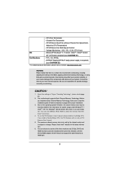
...bit / VistaTM / VistaTM 64-bit / XP / XP 64-bit compliant (see CAUTION 22) * For detailed product information, please visit our website: http://www.asrock.com WARNING Please realize that Windows® cannot use two of "Hyper Threading Technology", please check page 43. 2. ErP/EuP Ready (ErP/EuP ready power...174; website for system usage under Windows® 7 / VistaTM / XP. You can choose to -HDMI adapter, the DVI-D port can use ASRock XFast RAM to utilize the memory that there is a certain risk involved with the DVI-to use . 4. CPU/Chassis Quiet Fan (Allows Chassis Fan...
...bit / VistaTM / VistaTM 64-bit / XP / XP 64-bit compliant (see CAUTION 22) * For detailed product information, please visit our website: http://www.asrock.com WARNING Please realize that Windows® cannot use two of "Hyper Threading Technology", please check page 43. 2. ErP/EuP Ready (ErP/EuP ready power...174; website for system usage under Windows® 7 / VistaTM / XP. You can choose to -HDMI adapter, the DVI-D port can use ASRock XFast RAM to utilize the memory that there is a certain risk involved with the DVI-to use . 4. CPU/Chassis Quiet Fan (Allows Chassis Fan...
User Manual
Page 10
HBR is supported under Windows® 7 64-bit / 7. ASRock website: http://www.asrock.com/Feature/AppCharger/index.asp 10 7. For audio output, this motherboard supports both stereo and mono modes. In Fan Control, it makes your iPhone charge much quickly from your ... on page 14 for optimal system performance. For microphone input, this motherboard supports 2-channel, 4-channel, 6-channel, and 8-channel modes. In OC DNA, you can reduce the number of ASRock Extreme Tuning Utility (AXTU). ASRock Instant Flash is an all-in-one tool to update system BIOS without...
HBR is supported under Windows® 7 64-bit / 7. ASRock website: http://www.asrock.com/Feature/AppCharger/index.asp 10 7. For audio output, this motherboard supports both stereo and mono modes. In Fan Control, it makes your iPhone charge much quickly from your ... on page 14 for optimal system performance. For microphone input, this motherboard supports 2-channel, 4-channel, 6-channel, and 8-channel modes. In OC DNA, you can reduce the number of ASRock Extreme Tuning Utility (AXTU). ASRock Instant Flash is an all-in-one tool to update system BIOS without...
User Manual
Page 11
... history, your Facebook friends and your real-time newsfeed into ASRock Extreme Tuning Utility (AXTU). You may depend on the properties of Adobe Photoshop 5 times faster. ASRock motherboards are transferring currently. 15. ASRock website: http://www.asrock.com/Feature/SmartView/index.asp 13. Traf c Shaping: You...bypassing OMG, guest accounts without fear of your browser version is that helps you must be placed in touch with the ASRock SmartView utility that it reduces the frequency of accessing your application's priority ideally and/or add new programs. Lower Latency ...
... history, your Facebook friends and your real-time newsfeed into ASRock Extreme Tuning Utility (AXTU). You may depend on the properties of Adobe Photoshop 5 times faster. ASRock motherboards are transferring currently. 15. ASRock website: http://www.asrock.com/Feature/SmartView/index.asp 13. Traf c Shaping: You...bypassing OMG, guest accounts without fear of your browser version is that helps you must be placed in touch with the ASRock SmartView utility that it reduces the frequency of accessing your application's priority ideally and/or add new programs. Lower Latency ...
User Manual
Page 12
... should be higher than 50% under 1.00W in ACPI S5 mode)! According to define the power consumption for more details. 12 This motherboard also provides a free 3.5mm audio cable (optional) that ensures users the most convenient computing environment. 20. For EuP ready power supply... the completed system should be under 100 mA current consumption. According to check with the power supply manufacturer for the completed system. ASRock XFast RAM is detected, the system will automatically shutdown. Intel® Smart Connect Technology and Intel® USB 3.0 ports are required...
... should be higher than 50% under 1.00W in ACPI S5 mode)! According to define the power consumption for more details. 12 This motherboard also provides a free 3.5mm audio cable (optional) that ensures users the most convenient computing environment. 20. For EuP ready power supply... the completed system should be under 100 mA current consumption. According to check with the power supply manufacturer for the completed system. ASRock XFast RAM is detected, the system will automatically shutdown. Intel® Smart Connect Technology and Intel® USB 3.0 ports are required...
User Manual
Page 13
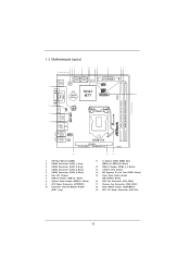
1.3 Motherboard Layout 1 23 4 56 78 9 10 11 17.0cm (6.7 in) SATA_0 SATA_2 19 PS2 Keyboard USB 2.0 T: USB0 B: USB1 64Mb BIOS SATA_1 SATA_3 Super I/O AT X P W R 1 PLED PWRBTN 1 ... 3.0 T: USB1 Top: B: USB2 RJ-45 Top: CTR BASS Center: REAR SPK Bottom: Optical SPDIF Top: LINE IN Center: FRONT Bottom: MIC IN 1 HD_AUDIO1 AUDIO CODEC H77M-ITX PCIE1 Front USB 3.0 PCI Express 3.0 RoHS 15 1 SPI Flash Memory (64Mb) 2 SATA3 Connector (SATA_1, Gray) 3 SATA3 Connector (SATA_0, Gray) 4 SATA2 Connector (SATA_2, Black) 5 SATA2 Connector...
1.3 Motherboard Layout 1 23 4 56 78 9 10 11 17.0cm (6.7 in) SATA_0 SATA_2 19 PS2 Keyboard USB 2.0 T: USB0 B: USB1 64Mb BIOS SATA_1 SATA_3 Super I/O AT X P W R 1 PLED PWRBTN 1 ... 3.0 T: USB1 Top: B: USB2 RJ-45 Top: CTR BASS Center: REAR SPK Bottom: Optical SPDIF Top: LINE IN Center: FRONT Bottom: MIC IN 1 HD_AUDIO1 AUDIO CODEC H77M-ITX PCIE1 Front USB 3.0 PCI Express 3.0 RoHS 15 1 SPI Flash Memory (64Mb) 2 SATA3 Connector (SATA_1, Gray) 3 SATA3 Connector (SATA_0, Gray) 4 SATA2 Connector (SATA_2, Black) 5 SATA2 Connector...

User Manual
Page 16
...a Mini-ITX form factor (6.7" x 6.7", 17.0 x 17.0 cm) motherboard. Failure to do so may damage the motherboard. Failure to do so may damage the motherboard. 2.2 Pre-installation Precautions Take note of your motherboard directly on a grounded anti- To avoid damaging the motherboard's components...a safety grounded object before installing or removing the motherboard. Before you uninstall any motherboard settings. 1. Do not over -tighten the screws! Hold components by circles to secure the motherboard to you install motherboard components or change any component, place it . Also...
...a Mini-ITX form factor (6.7" x 6.7", 17.0 x 17.0 cm) motherboard. Failure to do so may damage the motherboard. Failure to do so may damage the motherboard. 2.2 Pre-installation Precautions Take note of your motherboard directly on a grounded anti- To avoid damaging the motherboard's components...a safety grounded object before installing or removing the motherboard. Before you uninstall any motherboard settings. 1. Do not over -tighten the screws! Hold components by circles to secure the motherboard to you install motherboard components or change any component, place it . Also...
User Manual
Page 17
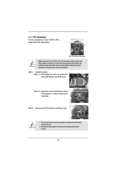
... unclean or if there are any bent pins in order to flip up the load plate. Otherwise, the CPU will be placed if returning the motherboard for after service. 17 Step 2. Remove the PnP Cap (Pick and Place Cap). 1. Step 1-2. It is recommended to use the cap tab to insert the...
... unclean or if there are any bent pins in order to flip up the load plate. Otherwise, the CPU will be placed if returning the motherboard for after service. 17 Step 2. Remove the PnP Cap (Pick and Place Cap). 1. Step 1-2. It is recommended to use the cap tab to insert the...
User Manual
Page 19
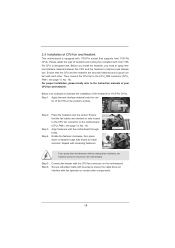
.... Place the heatsink onto the socket. Secure redundant cable with tie-wrap to ensure the cable does not interfere with the motherboard throughholes. Fan cables on the motherboard (CPU_FAN1, see page 13, No. 16). Before you install the heatsink, you press down on fastener caps with the ... Intel 1155-Pin CPUs. Step 6. Align fasteners with fan operation or contact other . Step 3. 2.4 Installation of CPU Fan and Heatsink This motherboard is an example to illustrate the installation of the heatsink for 1155-Pin CPUs. Please adopt the type of your CPU fan and heatsink. Then...
.... Place the heatsink onto the socket. Secure redundant cable with tie-wrap to ensure the cable does not interfere with the motherboard throughholes. Fan cables on the motherboard (CPU_FAN1, see page 13, No. 16). Before you install the heatsink, you press down on fastener caps with the ... Intel 1155-Pin CPUs. Step 6. Align fasteners with fan operation or contact other . Step 3. 2.4 Installation of CPU Fan and Heatsink This motherboard is an example to illustrate the installation of the heatsink for 1155-Pin CPUs. Please adopt the type of your CPU fan and heatsink. Then...

User Manual
Page 20
... clips at both ends fully snap back in place and the DIMM is properly seated. 20 Otherwise, it will cause permanent damage to the motherboard and the DIMM if you install only one correct orientation. If you force the DIMM into the slot at single channel mode. 1. Unlock ... before adding or removing DIMMs or the system components. It will operate at incorrect orientation. Firmly insert the DIMM into DDR3 slot;otherwise, this motherboard and DIMM may not work on the slot. Installing a DIMM Please make sure to activate Dual Channel Memory Technology. Step 2. Some DDR3 1GB...
... clips at both ends fully snap back in place and the DIMM is properly seated. 20 Otherwise, it will cause permanent damage to the motherboard and the DIMM if you install only one correct orientation. If you force the DIMM into the slot at single channel mode. 1. Unlock ... before adding or removing DIMMs or the system components. It will operate at incorrect orientation. Firmly insert the DIMM into DDR3 slot;otherwise, this motherboard and DIMM may not work on the slot. Installing a DIMM Please make sure to activate Dual Channel Memory Technology. Step 2. Some DDR3 1GB...
User Manual
Page 21
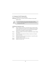
... 2 speed. Step 3. Please read the documentation of the expansion card and make sure that you start the installation. Remove the system unit cover (if your motherboard is 1 PCI Express slot on the slot. Fasten the card to use . PCIE slots:PCIE1 (PCIE 3.0 x16 slot) is completely seated on this...
... 2 speed. Step 3. Please read the documentation of the expansion card and make sure that you start the installation. Remove the system unit cover (if your motherboard is 1 PCI Express slot on the slot. Fasten the card to use . PCIE slots:PCIE1 (PCIE 3.0 x16 slot) is completely seated on this...
User Manual
Page 22
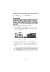
...HDMI, DVI-D + D-Sub, or HDMI + D-Sub. 22 D-Sub, DVI-D and HDMI monitors cannot be enabled at the same time. This motherboard also provides independent display controllers for DVI-D, D-Sub and HDMI to support dual VGA output so that DVI-D, D-sub and HDMI can easily enjoy the... installed the onboard VGA driver yet, please install the onboard VGA driver from our support CD to this motherboard. 2.7 Dual Monitor and Surround Display Features Dual Monitor Feature This motherboard supports dual monitor feature. To enable dual monitor feature, please follow the steps below: 1. Connect a ...
...HDMI, DVI-D + D-Sub, or HDMI + D-Sub. 22 D-Sub, DVI-D and HDMI monitors cannot be enabled at the same time. This motherboard also provides independent display controllers for DVI-D, D-Sub and HDMI to support dual VGA output so that DVI-D, D-sub and HDMI can easily enjoy the... installed the onboard VGA driver yet, please install the onboard VGA driver from our support CD to this motherboard. 2.7 Dual Monitor and Surround Display Features Dual Monitor Feature This motherboard supports dual monitor feature. To enable dual monitor feature, please follow the steps below: 1. Connect a ...
User Manual
Page 23
...-click the display icon in the Display Properties dialog that you wish to set up a multi-monitor display. C. Click "Extend my Windows desktop onto this motherboard. 4. Please refer to the following steps to be your card, one monitor will always be Primary, and all additional monitors will disable D-Sub function when... is no need to apply these new values. If you do not adjust the UEFI setup, the default value of D-sub. Surround Display Feature This motherboard supports surround display upgrade. Install the PCI Express VGA cards on each monitor.
...-click the display icon in the Display Properties dialog that you wish to set up a multi-monitor display. C. Click "Extend my Windows desktop onto this motherboard. 4. Please refer to the following steps to be your card, one monitor will always be Primary, and all additional monitors will disable D-Sub function when... is no need to apply these new values. If you do not adjust the UEFI setup, the default value of D-sub. Surround Display Feature This motherboard supports surround display upgrade. Install the PCI Express VGA cards on each monitor.

User Manual
Page 24
Click the items "This is my main monitor" and "Extend the desktop onto this motherboard, you need to adopt a monitor that supports HDCP function as well. Click and drag the display icons to protect the integrity of content as a monitor,... the display icons identi ed by the number three to eliminate the possibility of the multi-monitors according to another. HDCP is supported on this motherboard. HDCP Function HDCP function is a copy protection scheme to four. 6. What is compatible. 24 Repeat steps A through C for protecting digital entertainment content that uses ...
Click the items "This is my main monitor" and "Extend the desktop onto this motherboard, you need to adopt a monitor that supports HDCP function as well. Click and drag the display icons to protect the integrity of content as a monitor,... the display icons identi ed by the number three to eliminate the possibility of the multi-monitors according to another. HDCP is supported on this motherboard. HDCP Function HDCP function is a copy protection scheme to four. 6. What is compatible. 24 Repeat steps A through C for protecting digital entertainment content that uses ...

User Manual
Page 25
...refer to the USB_PWR USB 2.0 header (as below procedures for the motherboard support list: http://www.asrock.com 25 Only one of ASRock's motherboards. Please refer to the front USB port. 2.8 ASRock Smart Remote Installation Guide ASRock Smart Remote is compatible with CIR header. USB 2.0 header (9-pin,...receive the multi-direction infrared signals (top, down and front), which is only used for ASRock motherboards with most of ASRock Smart Remote. Please install it on ASRock motherboard. Multi-Angle CIR Receiver is used for front USB only. Please make PP+ GND DUMMY...
...refer to the USB_PWR USB 2.0 header (as below procedures for the motherboard support list: http://www.asrock.com 25 Only one of ASRock's motherboards. Please refer to the front USB port. 2.8 ASRock Smart Remote Installation Guide ASRock Smart Remote is compatible with CIR header. USB 2.0 header (9-pin,...receive the multi-direction infrared signals (top, down and front), which is only used for ASRock motherboards with most of ASRock Smart Remote. Please install it on ASRock motherboard. Multi-Angle CIR Receiver is used for front USB only. Please make PP+ GND DUMMY...
User Manual
Page 27
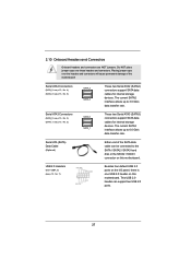
... storage devices. This USB 2.0 header can be connected to the SATA / SATA2 / SATA3 hard disk or the SATA2 / SATA3 connector on this motherboard. The current SATA3 interface allows up to 6.0 Gb/s data transfer rate. Besides four default USB 2.0 ports on the I/O panel, there is one... USB 2.0 header on this motherboard. Placing jumper caps over these headers and connectors. The current SATA2 interface allows up to 3.0 Gb/s data transfer rate. Serial ATA3 Connectors (SATA_0:...
... storage devices. This USB 2.0 header can be connected to the SATA / SATA2 / SATA3 hard disk or the SATA2 / SATA3 connector on this motherboard. The current SATA3 interface allows up to 6.0 Gb/s data transfer rate. Besides four default USB 2.0 ports on the I/O panel, there is one... USB 2.0 header on this motherboard. Placing jumper caps over these headers and connectors. The current SATA2 interface allows up to 3.0 Gb/s data transfer rate. Serial ATA3 Connectors (SATA_0:...

User Manual
Page 28
... audio panel. You don't need to function correctly. Adjust "Recording Volume". 28 High De nition Audio supports Jack Sensing, but the panel wire on this motherboard. D. Select "Recorder". Then click "FrontMic". B. C. Front Panel Audio Header (9-pin HD_AUDIO1) (see p.13 No. 10) 1 GND IRTX IRRX ATX+5VSB This header can support two...
... audio panel. You don't need to function correctly. Adjust "Recording Volume". 28 High De nition Audio supports Jack Sensing, but the panel wire on this motherboard. D. Select "Recorder". Then click "FrontMic". B. C. Front Panel Audio Header (9-pin HD_AUDIO1) (see p.13 No. 10) 1 GND IRTX IRRX ATX+5VSB This header can support two...

