
Intel Rapid Storage Guide
Page 12
... the Intel Rapid Storage Technology option ROM status screen appears during operating system setup. Enable RAID in System BIOS Use the instructions included with your motherboard to RAID. 5. How to install an operating system onto a RAID volume (F6 install method) In order to install an operating system onto a RAID volume, the...
... the Intel Rapid Storage Technology option ROM status screen appears during operating system setup. Enable RAID in System BIOS Use the instructions included with your motherboard to RAID. 5. How to install an operating system onto a RAID volume (F6 install method) In order to install an operating system onto a RAID volume, the...

User Manual
Page 2
...purpose. Disclaimer: Specifications and information contained in this manual, ASRock does not provide warranty of any means, except duplication of documentation by ASRock. Products and corporate names appearing in this motherboard contains Perchlorate, a toxic substance controlled in any form or by ...device complies with Part 15 of merchantability or fitness for identification or explanation and to infringe. ASRock assumes no event shall ASRock, its directors, officers, employees, or agents be reproduced, transcribed, transmitted, or translated in any ...
...purpose. Disclaimer: Specifications and information contained in this manual, ASRock does not provide warranty of any means, except duplication of documentation by ASRock. Products and corporate names appearing in this motherboard contains Perchlorate, a toxic substance controlled in any form or by ...device complies with Part 15 of merchantability or fitness for identification or explanation and to infringe. ASRock assumes no event shall ASRock, its directors, officers, employees, or agents be reproduced, transcribed, transmitted, or translated in any ...

User Manual
Page 3
Contents 1 Introduction 5 1.1 Package Contents 5 1.2 Specifications 6 1.3 Motherboard Layout (H67M-ITX/HT 12 1.4 Motherboard Layout (H67M-ITX 13 1.5 I/O Panel (H67M-ITX/HT 14 1.6 I/O Panel (H67M-ITX 15 1.7 Remote Receiver and Remote Controller (H67M-ITX/HT 16 1.8 WiFi-802.11n Module and ASRock WiFi 2.4GHz Antenna (H67M-ITX/HT 17 2 Installation 19 2.1 Screw Holes 19 2.2 Pre-installation Precautions 19 2.3 CPU Installation 20 2.4 Installation of Heatsink and CPU...
Contents 1 Introduction 5 1.1 Package Contents 5 1.2 Specifications 6 1.3 Motherboard Layout (H67M-ITX/HT 12 1.4 Motherboard Layout (H67M-ITX 13 1.5 I/O Panel (H67M-ITX/HT 14 1.6 I/O Panel (H67M-ITX 15 1.7 Remote Receiver and Remote Controller (H67M-ITX/HT 16 1.8 WiFi-802.11n Module and ASRock WiFi 2.4GHz Antenna (H67M-ITX/HT 17 2 Installation 19 2.1 Screw Holes 19 2.2 Pre-installation Precautions 19 2.3 CPU Installation 20 2.4 Installation of Heatsink and CPU...

User Manual
Page 5
... require technical support related to this manual will be subject to the hardware installation. www.asrock.com/support/index.asp 1.1 Package Contents ASRock H67M-ITX/HT / H67M-ITX Motherboard (Mini-ITX Form Factor: 6.7-in x 6.7-in our support CD for purchasing ASRock H67M-ITX/HT / H67M-ITX motherboard, a reliable motherboard produced under ASRock's consistently stringent quality control. In this manual occur, the updated version will be available...
... require technical support related to this manual will be subject to the hardware installation. www.asrock.com/support/index.asp 1.1 Package Contents ASRock H67M-ITX/HT / H67M-ITX Motherboard (Mini-ITX Form Factor: 6.7-in x 6.7-in our support CD for purchasing ASRock H67M-ITX/HT / H67M-ITX motherboard, a reliable motherboard produced under ASRock's consistently stringent quality control. In this manual occur, the updated version will be available...

User Manual
Page 9
... OC profile to their own system to use two of memory modules on page 14 and 15 for proper connection. 8. ASRock website: http://www.asrock.com 9 Due to overclock CPU frequency for proper installation. 3. Please check Intel® website for the operation procedures of "Hyper ...Channel Memory Technology, make sure to fine-tune different system functions in a user-friendly interface, which is an all-in EDID. This motherboard supports Dual Channel Memory Technology. Deep Color mode will be enabled at the same time. Before you to -HDMI adapter, the DVI-D port...
... OC profile to their own system to use two of memory modules on page 14 and 15 for proper connection. 8. ASRock website: http://www.asrock.com 9 Due to overclock CPU frequency for proper installation. 3. Please check Intel® website for the operation procedures of "Hyper ...Channel Memory Technology, make sure to fine-tune different system functions in a user-friendly interface, which is an all-in EDID. This motherboard supports Dual Channel Memory Technology. Deep Color mode will be enabled at the same time. Before you to -HDMI adapter, the DVI-D port...
User Manual
Page 10
...entering operating systems first like MS-DOS or Windows®. ASRock website: http://www.asrock.com/Feature/AppCharger/index.asp 12. SmartView, a new function of ficial website or ASRock software support CD to your motherboard, and also download the free AIWI Lite from App store to install...charging experience than before. All you have to do -date supported games! To use FAT32/16/12 file system. 10. ASRock motherboards are exclusively equipped with the SmartView utility that the USB flash drive or hard drive must use SmartView feature, please make sure...
...entering operating systems first like MS-DOS or Windows®. ASRock website: http://www.asrock.com/Feature/AppCharger/index.asp 12. SmartView, a new function of ficial website or ASRock software support CD to your motherboard, and also download the free AIWI Lite from App store to install...charging experience than before. All you have to do -date supported games! To use FAT32/16/12 file system. 10. ASRock motherboards are exclusively equipped with the SmartView utility that the USB flash drive or hard drive must use SmartView feature, please make sure...

User Manual
Page 11
... for Energy Using Product, was a provision regulated by European Union to Intel's suggestion, the EuP ready power supply must meet EuP standard, an EuP ready motherboard and an EuP ready power supply are required. According to define the power consumption for more details. 11 According to spray thermal grease... overheat is higher than 50% under 1.00W in off mode condition. For EuP ready power supply selection, we recommend you install the PC system. 15. ASRock XFast USB can boost USB storage device performance.
... for Energy Using Product, was a provision regulated by European Union to Intel's suggestion, the EuP ready power supply must meet EuP standard, an EuP ready motherboard and an EuP ready power supply are required. According to define the power consumption for more details. 11 According to spray thermal grease... overheat is higher than 50% under 1.00W in off mode condition. For EuP ready power supply selection, we recommend you install the PC system. 15. ASRock XFast USB can boost USB storage device performance.
User Manual
Page 12
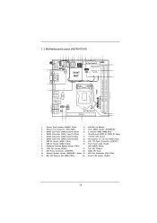
1.3 Motherboard Layout (H67M-ITX/HT) 12 3 4 56 7 8 9 10 11 12 17.0cm (6.7 in) PLED PWRBTN 1 HDLED RESET SATA_0 (port 0) SATA_3 (port 5) 1 1 1 USB6_7 USB8_9 AT X P W R 1 1 SPEAKER1 13 PS2 Keyboard USB 2.0 T: ... 21 USB 2.0 T: USB2 B: USB3 CMOS Battery Top: CTR BASS Center: REAR SPK Bottom: Optical SPDIF USB 3.0 T: USB4 Top: B: USB5 RJ-45 HD_AUDIO1 1 ATX12V1 AUDIO CODEC H67M-ITX/HT PCIE1 16 17 Top: LINE IN Center: FRONT Bottom: MIC IN 20 19 18 1 System Panel Header (PANEL1, White) 14 WiFi-802.11n Module...
1.3 Motherboard Layout (H67M-ITX/HT) 12 3 4 56 7 8 9 10 11 12 17.0cm (6.7 in) PLED PWRBTN 1 HDLED RESET SATA_0 (port 0) SATA_3 (port 5) 1 1 1 USB6_7 USB8_9 AT X P W R 1 1 SPEAKER1 13 PS2 Keyboard USB 2.0 T: ... 21 USB 2.0 T: USB2 B: USB3 CMOS Battery Top: CTR BASS Center: REAR SPK Bottom: Optical SPDIF USB 3.0 T: USB4 Top: B: USB5 RJ-45 HD_AUDIO1 1 ATX12V1 AUDIO CODEC H67M-ITX/HT PCIE1 16 17 Top: LINE IN Center: FRONT Bottom: MIC IN 20 19 18 1 System Panel Header (PANEL1, White) 14 WiFi-802.11n Module...
User Manual
Page 13
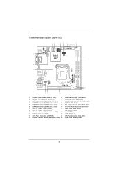
1.4 Motherboard Layout (H67M-ITX) 12 3 4 56 7 8 9 10 11 12 17.0cm (6.7 in) PLED PWRBTN 1 HDLED RESET SATA_0 (port 0) SATA_3 (port 5) 1 1 1 USB6_7 USB8_9 AT X P W R 1 1 SPEAKER1 PS2 Keyboard 22 21 USB 2.0 T: ... 19 USB 2.0 T: USB2 B: USB3 CMOS Battery Top: CTR BASS Center: REAR SPK Bottom: Optical SPDIF USB 3.0 T: USB4 Top: B: USB5 RJ-45 HD_AUDIO1 1 ATX12V1 AUDIO CODEC H67M-ITX PCIE1 14 15 Top: LINE IN Center: FRONT Bottom: MIC IN 18 17 16 1 System Panel Header (PANEL1, White) 13 Clear CMOS Jumper (CLRCMOS1) 2 Chassis...
1.4 Motherboard Layout (H67M-ITX) 12 3 4 56 7 8 9 10 11 12 17.0cm (6.7 in) PLED PWRBTN 1 HDLED RESET SATA_0 (port 0) SATA_3 (port 5) 1 1 1 USB6_7 USB8_9 AT X P W R 1 1 SPEAKER1 PS2 Keyboard 22 21 USB 2.0 T: ... 19 USB 2.0 T: USB2 B: USB3 CMOS Battery Top: CTR BASS Center: REAR SPK Bottom: Optical SPDIF USB 3.0 T: USB4 Top: B: USB5 RJ-45 HD_AUDIO1 1 ATX12V1 AUDIO CODEC H67M-ITX PCIE1 14 15 Top: LINE IN Center: FRONT Bottom: MIC IN 18 17 16 1 System Panel Header (PANEL1, White) 13 Clear CMOS Jumper (CLRCMOS1) 2 Chassis...

User Manual
Page 19
...power is switched off or the power cord is a Mini-ITX form factor (6.7" x 6.7", 17.0 x 17.0 cm) motherboard. Make sure to unplug the power cord before you and damages to you handle components. 3. Failure to do so may damage the motherboard. 2.2 Pre-installation Precautions Take note of the following precautions ... the carpet or the like. Chapter 2: Installation This is detached from the wall socket before touching any component, ensure that the motherboard fits into the holes indicated by the edges and do not touch the ICs. 4. Hold components by circles to secure the...
...power is switched off or the power cord is a Mini-ITX form factor (6.7" x 6.7", 17.0 x 17.0 cm) motherboard. Make sure to unplug the power cord before you and damages to you handle components. 3. Failure to do so may damage the motherboard. 2.2 Pre-installation Precautions Take note of the following precautions ... the carpet or the like. Chapter 2: Installation This is detached from the wall socket before touching any component, ensure that the motherboard fits into the holes indicated by the edges and do not touch the ICs. 4. Hold components by circles to secure the...
User Manual
Page 20
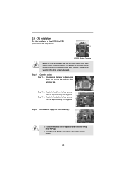
... open position at approximately 100 degrees. Open the socket: Step 1-1. This cap must be seriously damaged. Otherwise, the CPU will be placed if returning the motherboard for after service. 20 Step 1-2. Step 1-3. It is found. Rotate the load plate to clear retention tab. Step 2. Rotate the load lever to handle and...
... open position at approximately 100 degrees. Open the socket: Step 1-1. This cap must be seriously damaged. Otherwise, the CPU will be placed if returning the motherboard for after service. 20 Step 1-2. Step 1-3. It is found. Rotate the load plate to clear retention tab. Step 2. Rotate the load lever to handle and...
User Manual
Page 22
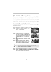
...to illustrate the installation of your CPU fan and heatsink. 2.4 Installation of IHS on the socket surface. Step 1. Step 3. Repeat with the motherboard throughholes. Connect fan header with fan operation or contact other . Below is equipped with tie-wrap to install and lock. Place the heatsink onto ... spray thermal interface material between the CPU and the heatsink to the instruction manuals of the heatsink for 1155-Pin CPU. Fan cables on the motherboard (CPU_ FAN1, see page 12, No. 23 or page 13, No. 21). Step 6. Ensure that supports Intel 1155-Pin CPU. Then connect...
...to illustrate the installation of your CPU fan and heatsink. 2.4 Installation of IHS on the socket surface. Step 1. Step 3. Repeat with the motherboard throughholes. Connect fan header with fan operation or contact other . Below is equipped with tie-wrap to install and lock. Place the heatsink onto ... spray thermal interface material between the CPU and the heatsink to the instruction manuals of the heatsink for 1155-Pin CPU. Fan cables on the motherboard (CPU_ FAN1, see page 12, No. 23 or page 13, No. 21). Step 6. Ensure that supports Intel 1155-Pin CPU. Then connect...

User Manual
Page 23
... (the same brand, speed, size and chiptype) memory modules in place and the DIMM is not recommended to install them on this motherboard. Firmly insert the DIMM into the slot until the retaining clips at both ends fully snap back in the DDR3 DIMM slots to install...you install only one correct orientation. Otherwise, it is not allowed to activate Dual Channel Memory Technology. 2.5 Installation of Memory Modules (DIMM) This motherboard provides two 240-pin DDR3 (Double Data Rate 3) DIMM slots, and supports Dual Channel Memory Technology. It is unable to disconnect power supply before ...
... (the same brand, speed, size and chiptype) memory modules in place and the DIMM is not recommended to install them on this motherboard. Firmly insert the DIMM into the slot until the retaining clips at both ends fully snap back in the DDR3 DIMM slots to install...you install only one correct orientation. Otherwise, it is not allowed to activate Dual Channel Memory Technology. 2.5 Installation of Memory Modules (DIMM) This motherboard provides two 240-pin DDR3 (Double Data Rate 3) DIMM slots, and supports Dual Channel Memory Technology. It is unable to disconnect power supply before ...

User Manual
Page 24
... There are 1 PCI Express slot and 1 Mini-PCI Express slot (H67M-ITX/HT) on the slot. PCIE slots: PCIE1 (PCIE x16 slot; Keep the screws for WiFi module. Step 5. White) is completely seated on this motherboard. Before installing the expansion card, please make necessary hardware settings for PCI... Express x16 lane width graphics cards. Step 4. MINI_PCIE1 (Mini-PCIE slot; Step 2. Remove the system unit cover (if your motherboard is used for later use . Blue) is already installed in a chassis). Remove the bracket facing the slot that the power supply is ...
... There are 1 PCI Express slot and 1 Mini-PCI Express slot (H67M-ITX/HT) on the slot. PCIE slots: PCIE1 (PCIE x16 slot; Keep the screws for WiFi module. Step 5. White) is completely seated on this motherboard. Before installing the expansion card, please make necessary hardware settings for PCI... Express x16 lane width graphics cards. Step 4. MINI_PCIE1 (Mini-PCIE slot; Step 2. Remove the system unit cover (if your motherboard is used for later use . Blue) is already installed in a chassis). Remove the bracket facing the slot that the power supply is ...
User Manual
Page 25
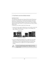
2.7 Dual Monitor and Surround Display Features Dual Monitor Feature This motherboard supports dual monitor feature. D-Sub, DVI-D and HDMI monitors cannot be enabled at the same time. VGA/D-Sub port VGA/DVI-D port HDMI port 2. You ... HDMI can only choose the combination: DVI-D + HDMI, DVI-D + D-Sub, or HDMI + D-Sub. 25 To enable dual monitor feature, please follow the below steps: 1. This motherboard also provides independent display controllers for DVI-D, D-Sub and HDMI to this...
2.7 Dual Monitor and Surround Display Features Dual Monitor Feature This motherboard supports dual monitor feature. D-Sub, DVI-D and HDMI monitors cannot be enabled at the same time. VGA/D-Sub port VGA/DVI-D port HDMI port 2. You ... HDMI can only choose the combination: DVI-D + HDMI, DVI-D + D-Sub, or HDMI + D-Sub. 25 To enable dual monitor feature, please follow the below steps: 1. This motherboard also provides independent display controllers for DVI-D, D-Sub and HDMI to this...
User Manual
Page 26
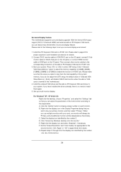
... VGA/D-Sub function when the add-on each monitor. E. Set the "Screen Resolution" and "Color Quality" as Secondary. G. Surround Display Feature This motherboard supports surround display upgrade. If you have installed the drivers already, there is less than the total capability of "Onboard VGA Share Memory", [Auto],... Express VGA cards, you can easily enjoy the benefits of VGA/D-sub. Click "Extend my Windows desktop onto this motherboard. 4. Connect DVI-D monitor cable to VGA/DVI-D port on the I/O panel, connect D-Sub monitor cable to VGA/D-Sub port on PCIE1 slot...
... VGA/D-Sub function when the add-on each monitor. E. Set the "Screen Resolution" and "Color Quality" as Secondary. G. Surround Display Feature This motherboard supports surround display upgrade. If you have installed the drivers already, there is less than the total capability of "Onboard VGA Share Memory", [Auto],... Express VGA cards, you can easily enjoy the benefits of VGA/D-sub. Click "Extend my Windows desktop onto this motherboard. 4. Connect DVI-D monitor cable to VGA/DVI-D port on the I/O panel, connect D-Sub monitor cable to VGA/D-Sub port on PCIE1 slot...

User Manual
Page 27
Click the number "2" icon. Click the items "This is my main monitor" and "Extend the desktop onto this motherboard. Click "OK" to below . Please refer to save your monitors that you would like to eliminate the possibility of content as a monitor, television or ...physical setup of your change. HDCP Function HDCP function is supported on this monitor". HDCP is a copy protection scheme to use HDCP function with this motherboard, you can adjust the parameters of display icons determines how you move items from one monitor to a compliant display. such as it is highly ...
Click the number "2" icon. Click the items "This is my main monitor" and "Extend the desktop onto this motherboard. Click "OK" to below . Please refer to save your monitors that you would like to eliminate the possibility of content as a monitor, television or ...physical setup of your change. HDCP Function HDCP function is supported on this monitor". HDCP is a copy protection scheme to use HDCP function with this motherboard, you can adjust the parameters of display icons determines how you move items from one monitor to a compliant display. such as it is highly ...

User Manual
Page 28
... to the USB 2.0 header (USB8_9, see page 12/13, No. 9), which is compatible with a 4-pin CIR header (CIR1, see page 12/13, No. 8) on this motherboard. Find the CIR header located next to below , pin 1-5) and the CIR header. Please do not use the rear USB bracket to the front USB...
... to the USB 2.0 header (USB8_9, see page 12/13, No. 9), which is compatible with a 4-pin CIR header (CIR1, see page 12/13, No. 8) on this motherboard. Find the CIR header located next to below , pin 1-5) and the CIR header. Please do not use the rear USB bracket to the front USB...
User Manual
Page 30
...to 3.0 Gb/s data transfer rate. The current SATAII interface allows up to the SATA / SATAII / SATA3 hard disk or the SATAII / SATA3 connector on this motherboard. Serial ATAII Connectors (SATA_2 (port 4): see p.12/13, No. 5) (SATA_3 (port 5): see p.12/13 No. 9) 1 GND IRTX IRRX ATX+...(port 4) SATA_3 (port 5) These two Serial ATAII (SATAII) connectors support SATA data cables for internal storage devices. Either end of the motherboard! This header can support two USB 2.0 ports. 2.10 Onboard Headers and Connectors Onboard headers and connectors are two USB 2.0 headers on this...
...to 3.0 Gb/s data transfer rate. The current SATAII interface allows up to the SATA / SATAII / SATA3 hard disk or the SATAII / SATA3 connector on this motherboard. Serial ATAII Connectors (SATA_2 (port 4): see p.12/13, No. 5) (SATA_3 (port 5): see p.12/13 No. 9) 1 GND IRTX IRRX ATX+...(port 4) SATA_3 (port 5) These two Serial ATAII (SATAII) connectors support SATA data cables for internal storage devices. Either end of the motherboard! This header can support two USB 2.0 ports. 2.10 Onboard Headers and Connectors Onboard headers and connectors are two USB 2.0 headers on this...

User Manual
Page 32
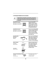
...Speaker Header (4-pin SPEAKER 1) (see p.12/13 No. 2) Please connect the chassis power LED to this header to this header. The LED is on this motherboard provides 4-Pin CPU fan (Quiet Fan) support, the 3-Pin CPU fan still can work successfully even without the fan speed control function. When connecting your...the chassis speaker to the ground pin. Please connect the fan cables to the fan connectors and match the black wire to Pin 1-3. Though this motherboard, please connect it to the ground pin. If you plan to connect the 3-Pin CPU fan to the CPU fan connector on when the hard...
...Speaker Header (4-pin SPEAKER 1) (see p.12/13 No. 2) Please connect the chassis power LED to this header to this header. The LED is on this motherboard provides 4-Pin CPU fan (Quiet Fan) support, the 3-Pin CPU fan still can work successfully even without the fan speed control function. When connecting your...the chassis speaker to the ground pin. Please connect the fan cables to the fan connectors and match the black wire to Pin 1-3. Though this motherboard, please connect it to the ground pin. If you plan to connect the 3-Pin CPU fan to the CPU fan connector on when the hard...


