
User Manual
Page 6
Micro ATX Form Factor: 9.6-in x 8.6-in LGA1155 Package - Solid Capacitor for CPU power - Pixel Shader 4.1, DirectX 10.1 - Supports HDMI 1.4a Technology with HDMI 1.4a - resolution up to 1920x1200 @ 60Hz - Supports Blu-ray Stereoscopic 3D with max. Atheros® ...
Micro ATX Form Factor: 9.6-in x 8.6-in LGA1155 Package - Solid Capacitor for CPU power - Pixel Shader 4.1, DirectX 10.1 - Supports HDMI 1.4a Technology with HDMI 1.4a - resolution up to 1920x1200 @ 60Hz - Supports Blu-ray Stereoscopic 3D with max. Atheros® ...

User Manual
Page 7
... 6 x Ready-to-Use USB 2.0 Ports - 1 x RJ-45 LAN Port with GUI support - SMBIOS 2.3.1 Support - ASRock Extreme Tuning Utility (AXTU) (see CAUTION 8) - ASRock Instant Flash (see CAUTION 7) - ASRock AIWI (see CAUTION 13) - Front panel audio connector - 2 x USB 2.0 headers (support 4 USB 2.0 ports) -...) - Instant Boot - Creative Sound Blaster X-Fi MB - ASRock APP Charger (see CAUTION 11) - ASRock XFast USB (see CAUTION 12) - CPU/Chassis/Power FAN connector - 24 pin ATX power connector - 8 pin 12V power connector - HD Audio Jack: Line in/Front Speaker/Microphone -...
... 6 x Ready-to-Use USB 2.0 Ports - 1 x RJ-45 LAN Port with GUI support - SMBIOS 2.3.1 Support - ASRock Extreme Tuning Utility (AXTU) (see CAUTION 8) - ASRock Instant Flash (see CAUTION 7) - ASRock AIWI (see CAUTION 13) - Front panel audio connector - 2 x USB 2.0 headers (support 4 USB 2.0 ports) -...) - Instant Boot - Creative Sound Blaster X-Fi MB - ASRock APP Charger (see CAUTION 11) - ASRock XFast USB (see CAUTION 12) - CPU/Chassis/Power FAN connector - 24 pin ATX power connector - 8 pin 12V power connector - HD Audio Jack: Line in/Front Speaker/Microphone -...
User Manual
Page 8
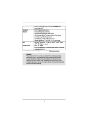
...-Adjust by overclocking. 8 Voltage Monitoring: +12V, +5V, +3.3V, CPU Vcore OS - Good Night LED Hardware - CPU/Chassis/Power Fan Tachometer - CPU/Chassis Fan Multi-Speed Control - Combo Cooler Option (C.C.O.) (see CAUTION 15) * For detailed product information, please visit ...our website: http://www.asrock.com WARNING Please realize that there is required) (see CAUTION 14) - Chassis Temperature Sensing - ErP/EuP Ready (ErP/EuP ready power supply is a certain risk involved with overclocking, including adjusting the ...
...-Adjust by overclocking. 8 Voltage Monitoring: +12V, +5V, +3.3V, CPU Vcore OS - Good Night LED Hardware - CPU/Chassis/Power Fan Tachometer - CPU/Chassis Fan Multi-Speed Control - Combo Cooler Option (C.C.O.) (see CAUTION 15) * For detailed product information, please visit ...our website: http://www.asrock.com WARNING Please realize that there is required) (see CAUTION 14) - Chassis Temperature Sensing - ErP/EuP Ready (ErP/EuP ready power supply is a certain risk involved with overclocking, including adjusting the ...

User Manual
Page 10
....asp 11. SmartView, a new function of ficial website or ASRock software support CD to your motherboard, and also download the free AIWI Lite from your most up to RAM (S3), hibernation mode (S4) or power off (S5). Combo Cooler Option (C.C.O.) provides the flexible option ...7 / 7 64 bit / VistaTM / VistaTM 64 bit, and your PC games. ASRock website: http://www.asrock.com/Feature/ SmartView/index.asp 12. The performance may depend on the motherboard functions properly and unplug the power cord, then plug it makes your iPhone charged much quickly from App store to control...
....asp 11. SmartView, a new function of ficial website or ASRock software support CD to your motherboard, and also download the free AIWI Lite from your most up to RAM (S3), hibernation mode (S4) or power off (S5). Combo Cooler Option (C.C.O.) provides the flexible option ...7 / 7 64 bit / VistaTM / VistaTM 64 bit, and your PC games. ASRock website: http://www.asrock.com/Feature/ SmartView/index.asp 12. The performance may depend on the motherboard functions properly and unplug the power cord, then plug it makes your iPhone charged much quickly from App store to control...

User Manual
Page 11
... must meet EuP standard, an EuP ready motherboard and an EuP ready power supply are required. For EuP ready power supply selection, we recommend you checking with the power supply manufacturer for the completed system. According to define the power consumption for more details. 11 To meet the standard of the completed... system shall be under 100 mA current consumption. EuP, stands for Energy Using Product, was a provision regulated by European Union to EuP, the total AC power of 5v standby power efficiency is higher than 50% under 1.00W in off mode condition. 15.
... must meet EuP standard, an EuP ready motherboard and an EuP ready power supply are required. For EuP ready power supply selection, we recommend you checking with the power supply manufacturer for the completed system. According to define the power consumption for more details. 11 To meet the standard of the completed... system shall be under 100 mA current consumption. EuP, stands for Energy Using Product, was a provision regulated by European Union to EuP, the total AC power of 5v standby power efficiency is higher than 50% under 1.00W in off mode condition. 15.

User Manual
Page 12
...B: USB5 RJ-45 Top: LINE IN Center: FRONT Bottom: MIC IN 26 25 24 LAN PHY HD_AUDIO1 1 PCI Express 2.0 RoHS CMOS Battery PCIE1 H61M PCI1 PCI2 23 AUDIO CODEC 1 LPT1 PCIE2 COM1 1 Super I/O Dual Channel DX10.1 CHA_FAN1 Intel H61 32Mb BIOS SATA2_0 1 CLRCMOS1 IR1 1 PANEL1 PLED..., Blue) 2 1155-Pin CPU Socket 15 SATA2 Connector (SATA2_3, Blue) 3 CPU Fan Connector (CPU_FAN1) 16 Consumer Infrared Module Header (CIR1) 4 ATX 12V Power Connector (ATX12V1) 17 USB 2.0 Header (USB6_7, Blue) 5 2 x 240-pin DDR3 DIMM Slots 18 System Panel Header (PANEL1, White) (Dual Channel: DDR3_A1...
...B: USB5 RJ-45 Top: LINE IN Center: FRONT Bottom: MIC IN 26 25 24 LAN PHY HD_AUDIO1 1 PCI Express 2.0 RoHS CMOS Battery PCIE1 H61M PCI1 PCI2 23 AUDIO CODEC 1 LPT1 PCIE2 COM1 1 Super I/O Dual Channel DX10.1 CHA_FAN1 Intel H61 32Mb BIOS SATA2_0 1 CLRCMOS1 IR1 1 PANEL1 PLED..., Blue) 2 1155-Pin CPU Socket 15 SATA2 Connector (SATA2_3, Blue) 3 CPU Fan Connector (CPU_FAN1) 16 Consumer Infrared Module Header (CIR1) 4 ATX 12V Power Connector (ATX12V1) 17 USB 2.0 Header (USB6_7, Blue) 5 2 x 240-pin DDR3 DIMM Slots 18 System Panel Header (PANEL1, White) (Dual Channel: DDR3_A1...

User Manual
Page 14
... note of your motherboard directly on a grounded antistatic pad or in the bag that the power is switched off or the power cord is a Micro ATX form factor (9.6" x 8.6", 24.4 x 21.8 cm) motherboard. Unplug the power cord from the power supply. Whenever you install or remove any component, place it . Before you install the motherboard... or change any component. 2. Make sure to use a grounded wrist strap or touch a safety grounded object before you handle components. 3. Also remember to unplug the power cord before touching any motherboard settings. 1.
... note of your motherboard directly on a grounded antistatic pad or in the bag that the power is switched off or the power cord is a Micro ATX form factor (9.6" x 8.6", 24.4 x 21.8 cm) motherboard. Unplug the power cord from the power supply. Whenever you install or remove any component, place it . Before you install the motherboard... or change any component. 2. Make sure to use a grounded wrist strap or touch a safety grounded object before you handle components. 3. Also remember to unplug the power cord before touching any motherboard settings. 1.

User Manual
Page 18
... break notch break The DIMM only fits in one memory module or two non-identical memory modules, it will cause permanent damage to disconnect power supply before adding or removing DIMMs or the system components. Step 3. Step 2.
... break notch break The DIMM only fits in one memory module or two non-identical memory modules, it will cause permanent damage to disconnect power supply before adding or removing DIMMs or the system components. Step 3. Step 2.

User Manual
Page 19
... used for PCI Express x16 lane width graphics cards. Please read the documentation of the expansion card and make sure that the power supply is switched off or the power cord is already installed in a chassis). Step 6. Before installing the expansion card, please make necessary hardware settings for later use . Step 2. PCIE2...
... used for PCI Express x16 lane width graphics cards. Please read the documentation of the expansion card and make sure that the power supply is switched off or the power cord is already installed in a chassis). Step 6. Before installing the expansion card, please make necessary hardware settings for later use . Step 2. PCIE2...
User Manual
Page 24
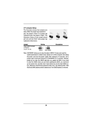
... shut it down before you do not clear the CMOS right after you to default setup, please turn off the computer and unplug the power cord from the power supply. Please be noted that the password, date, time, user default profile, 1394 GUID and MAC address will be cleared only...
... shut it down before you do not clear the CMOS right after you to default setup, please turn off the computer and unplug the power cord from the power supply. Please be noted that the password, date, time, user default profile, 1394 GUID and MAC address will be cleared only...

User Manual
Page 27
... LED): Connect to the reset switch on the chassis front panel. The LED is off when the system is in S1 sleep state. Connect the power switch, reset switch and system status indicator on when the system is operating. The LED is reading or writing data. A front panel module mainly ...consists of power switch, reset switch, power LED, hard drive activity LED, speaker and etc. The LED is on when the hard drive is on the chassis to this header according...
... LED): Connect to the reset switch on the chassis front panel. The LED is off when the system is in S1 sleep state. Connect the power switch, reset switch and system status indicator on when the system is operating. The LED is reading or writing data. A front panel module mainly ...consists of power switch, reset switch, power LED, hard drive activity LED, speaker and etc. The LED is on when the hard drive is on the chassis to this header according...

User Manual
Page 28
...Quiet Fan) support, the 3-Pin CPU fan still can still work if you adopt a traditional 20-pin ATX power supply. Though this motherboard provides 8-pin ATX 12V power connector, it can still work successfully even without the fan speed control function. To use the 20-pin ATX... port Header (9-pin COM1) (see p.12 No. 7) 12 24 Please connect an ATX power supply to Pin 1-3. Pin 1-3 Connected 3-Pin Fan Installation ATX Power Connector (24-pin ATXPWR1) (see p.12 No. 21) 4-Pin ATX 12V Power Supply Installation 4 1 This COM1 header supports a serial port module. 28 To use the ...
...Quiet Fan) support, the 3-Pin CPU fan still can still work if you adopt a traditional 20-pin ATX power supply. Though this motherboard provides 8-pin ATX 12V power connector, it can still work successfully even without the fan speed control function. To use the 20-pin ATX... port Header (9-pin COM1) (see p.12 No. 7) 12 24 Please connect an ATX power supply to Pin 1-3. Pin 1-3 Connected 3-Pin Fan Installation ATX Power Connector (24-pin ATXPWR1) (see p.12 No. 21) 4-Pin ATX 12V Power Supply Installation 4 1 This COM1 header supports a serial port module. 28 To use the ...

User Manual
Page 29
...) Hard Disks Installation This motherboard adopts Intel® H61 chipset that supports Serial ATA (SATA) / Serial ATAII (SATAII) hard disks. nector. STEP 2: Connect the SATA power cable to the SATA / SATAII hard disk. 29 STEP 1: Install the SATA / SATAII hard disks into the drive bays of the SATA data cable to...
...) Hard Disks Installation This motherboard adopts Intel® H61 chipset that supports Serial ATA (SATA) / Serial ATAII (SATAII) hard disks. nector. STEP 2: Connect the SATA power cable to the SATA / SATAII hard disk. 29 STEP 1: Install the SATA / SATAII hard disks into the drive bays of the SATA data cable to...

User Manual
Page 30
... RAID configuration, it cannot perform Hot Plug if the OS has been installed into the SATA / SATAII HDD. 30 NOTE What is still power-on and in AHCI mode.
... RAID configuration, it cannot perform Hot Plug if the OS has been installed into the SATA / SATAII HDD. 30 NOTE What is still power-on and in AHCI mode.

User Manual
Page 31
... SATA / SATAII driver is available on our website: www.asrock.com 2. Before you process the Hot Plug: 1. SATA data cable (Red) B. Points of our motherboard is definitely not able to power supply Caution 1. SATA power cable with SATA 15-pin power connector interface A. SATA power cable SATA 7-pin connector The SATA 15-pin...
... SATA / SATAII driver is available on our website: www.asrock.com 2. Before you process the Hot Plug: 1. SATA data cable (Red) B. Points of our motherboard is definitely not able to power supply Caution 1. SATA power cable with SATA 15-pin power connector interface A. SATA power cable SATA 7-pin connector The SATA 15-pin...

User Manual
Page 32
... end Step 2 Connect SATA data cable to (White) to SATA / SATAII HDD. the motherboard's SATAII connector. SATA power cable 1x4-pin power connector (White) Step 3 Connect SATA 15-pin power cable connector (Black) end to the power supply 1x4-pin cable. Step 4 Connect SATA data cable to process the Hot Plug, improper procedure will... below instruction sequence to process the Hot Unplug, improper procedure will cause the SATA / SATAII HDD damage and data loss. Step 2 Unplug SATA 15-pin power cable connector (Black) from SATA / SATAII HDD side.
... end Step 2 Connect SATA data cable to (White) to SATA / SATAII HDD. the motherboard's SATAII connector. SATA power cable 1x4-pin power connector (White) Step 3 Connect SATA 15-pin power cable connector (Black) end to the power supply 1x4-pin cable. Step 4 Connect SATA data cable to process the Hot Plug, improper procedure will... below instruction sequence to process the Hot Unplug, improper procedure will cause the SATA / SATAII HDD damage and data loss. Step 2 Unplug SATA 15-pin power cable connector (Black) from SATA / SATAII HDD side.

User Manual
Page 35
Please press or during the Power-On-Self-Test (POST) to enter the UEFI SETUP UTILITY, otherwise, POST will continue with the following UEFI setup screens and descriptions are for reference ...
Please press or during the Power-On-Self-Test (POST) to enter the UEFI SETUP UTILITY, otherwise, POST will continue with the following UEFI setup screens and descriptions are for reference ...

User Manual
Page 37
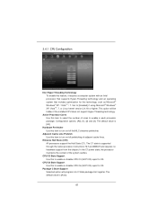
...Enabled]. Please note that enabling this item to [Disable] if above issue occurs. CPU Ratio Setting Use this item to adjust Turbo Boost power limit. Configuration options: [Enabled] and [Disabled]. If you can switch between multiple frequency and voltage points to system stability or ...expense. Intel SpeedStep Technology Intel SpeedStep technology is [Auto]. 37 Please note that overclocking may reduce CPU voltage and lead to enable power savings. Turbo Boost allows processor cores to enable or disable GT Over Clock by Internal Graphics Device. GT Over Clock Use this ...
...Enabled]. Please note that enabling this item to [Disable] if above issue occurs. CPU Ratio Setting Use this item to adjust Turbo Boost power limit. Configuration options: [Enabled] and [Disabled]. If you can switch between multiple frequency and voltage points to system stability or ...expense. Intel SpeedStep Technology Intel SpeedStep technology is [Auto]. 37 Please note that overclocking may reduce CPU voltage and lead to enable power savings. Turbo Boost allows processor cores to enable or disable GT Over Clock by Internal Graphics Device. GT Over Clock Use this ...

User Manual
Page 39
...: [Auto], [Slow] and [Fast]. The default value is [Disabled]. The default value is [Auto]. PCH Voltage Use this to adjust DDR power down mode. Memory Power Down Mode Use this item to select PCH Voltage. The default value is [Auto]. The default value is [Auto]. The default is [Auto].... this item to select CPU PLL Voltage. ODT NOM (CHB) Use this to change ODT WR (CHA) Auto/Manual setting. Voltage Control Power Saving Mode Use this to enable or disable Power Saving Mode. IGPU Voltage Offset Use this to select IGPU Voltage Offset. The default value is [Auto].
...: [Auto], [Slow] and [Fast]. The default value is [Disabled]. The default value is [Auto]. PCH Voltage Use this to adjust DDR power down mode. Memory Power Down Mode Use this item to select PCH Voltage. The default value is [Auto]. The default value is [Auto]. The default is [Auto].... this item to select CPU PLL Voltage. ODT NOM (CHB) Use this to change ODT WR (CHA) Auto/Manual setting. Voltage Control Power Saving Mode Use this to enable or disable Power Saving Mode. IGPU Voltage Offset Use this to select IGPU Voltage Offset. The default value is [Auto].
User Manual
Page 41
Active Processor Cores Use this item to turn on /off prefetching of adjacent cache lines. In the C1 power state, the processor maintains the context of cores to OS. The default value is supported through the native processor instructions HLT and MWAIT and requires ...
Active Processor Cores Use this item to turn on /off prefetching of adjacent cache lines. In the C1 power state, the processor maintains the context of cores to OS. The default value is supported through the native processor instructions HLT and MWAIT and requires ...


