
User Manual
Page 13
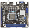
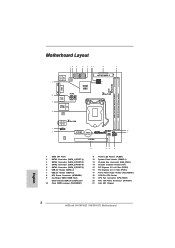
1.3 Motherboard Layout (H61M-VG3 / H61M-VS3) 12 3 4 5 67 8 9 DDR3 Fast RAM X DDR3_A1 (64 bit, 240-pin module) DDR3_B1 (64 bit, 240-pin module) SATA_0 (PORT 0) SATA_2 (PORT 4) PS2 Mouse PS2 Keyboard 32Mb BIOS SATA_1 (PORT 1) SATA_3 (PORT 5) 21 Intel H61 VGA1 RoHS 20 CPU_FAN1 USB 2.0 T: USB0 B: USB1 ATX12V1 19 USB 2.0 T: USB2 Top: B: ...14 Chassis Intrusion Header (CI1) 15 PCI Express 3.0 x16 Slot (PCIE2) 16 PCI Express 2.0 x1 Slot (PCIE1) 17 Front Panel Audio Header (HD_AUDIO1) 18 1155-Pin CPU Socket 19 CPU Fan Connector (CPU_FAN1) 20 ATX 12V Power Connector (ATX12V1) 21...
1.3 Motherboard Layout (H61M-VG3 / H61M-VS3) 12 3 4 5 67 8 9 DDR3 Fast RAM X DDR3_A1 (64 bit, 240-pin module) DDR3_B1 (64 bit, 240-pin module) SATA_0 (PORT 0) SATA_2 (PORT 4) PS2 Mouse PS2 Keyboard 32Mb BIOS SATA_1 (PORT 1) SATA_3 (PORT 5) 21 Intel H61 VGA1 RoHS 20 CPU_FAN1 USB 2.0 T: USB0 B: USB1 ATX12V1 19 USB 2.0 T: USB2 Top: B: ...14 Chassis Intrusion Header (CI1) 15 PCI Express 3.0 x16 Slot (PCIE2) 16 PCI Express 2.0 x1 Slot (PCIE1) 17 Front Panel Audio Header (HD_AUDIO1) 18 1155-Pin CPU Socket 19 CPU Fan Connector (CPU_FAN1) 20 ATX 12V Power Connector (ATX12V1) 21...

User Manual
Page 17
...avoid kicking off the PnP cap. 2. Step 1-3. Load Plate Load Lever Contact Array Socket Body 1155-Pin Socket Overview Before you insert the 1155-Pin CPU into the socket if above situation is found. Open the socket: Step 1-1. Remove PnP Cap (Pick and Place Cap). 1. It is any ...position at approximately 100 degrees. Disengaging the lever by depressing down and out on the socket. Step 1-2. Step 2. This cap must be seriously damaged. 2.3 CPU Installation For the installation of Intel 1155-Pin CPU, please follow the steps below. Do not force to clear retention tab....
...avoid kicking off the PnP cap. 2. Step 1-3. Load Plate Load Lever Contact Array Socket Body 1155-Pin Socket Overview Before you insert the 1155-Pin CPU into the socket if above situation is found. Open the socket: Step 1-1. Remove PnP Cap (Pick and Place Cap). 1. It is any ...position at approximately 100 degrees. Disengaging the lever by depressing down and out on the socket. Step 1-2. Step 2. This cap must be seriously damaged. 2.3 CPU Installation For the installation of Intel 1155-Pin CPU, please follow the steps below. Do not force to clear retention tab....

User Manual
Page 19
... to illustrate the installation of the heatsink for 1155-Pin CPU. Step 4. Please adopt the type of heatsink and cooling fan compliant with each other components. 19 Ensure that supports Intel 1155-Pin CPU. Repeat with 1155-Pin socket that the CPU and the heatsink are oriented ...on side closest to the CPU fan connector on the motherboard. Place the heatsink onto the socket. Step 6. For proper installation, please kindly...
... to illustrate the installation of the heatsink for 1155-Pin CPU. Step 4. Please adopt the type of heatsink and cooling fan compliant with each other components. 19 Ensure that supports Intel 1155-Pin CPU. Repeat with 1155-Pin socket that the CPU and the heatsink are oriented ...on side closest to the CPU fan connector on the motherboard. Place the heatsink onto the socket. Step 6. For proper installation, please kindly...
Quick Installation Guide
Page 2
... bit, 240-pin module) DDR3_B1 (64 bit, 240-pin module) SATA_0 (PORT 0) SATA_2 (PORT 4) PS2 Mouse PS2 Keyboard 21 32Mb BIOS SATA_1 (PORT 1) SATA_3 (PORT 5) Intel H61 VGA1 RoHS 20 CPU_FAN1 USB 2.0 T: USB0 B: USB1 ATX12V1 19 USB 2.0 T: USB2 Top: B: USB3 RJ-45 18 LAN AT X P W R 1 1 USB4_5 1... Header (CI1) 15 PCI Express 3.0 x16 Slot (PCIE2) 16 PCI Express 2.0 x1 Slot (PCIE1) 17 Front Panel Audio Header (HD_AUDIO1) 18 1155-Pin CPU Socket 19 CPU Fan Connector (CPU_FAN1) 20 ATX 12V Power Connector (ATX12V1) 21 Intel H61 Chipset English 2 ASRock H61M-VG3 / H61M-VS3 Motherboard
... bit, 240-pin module) DDR3_B1 (64 bit, 240-pin module) SATA_0 (PORT 0) SATA_2 (PORT 4) PS2 Mouse PS2 Keyboard 21 32Mb BIOS SATA_1 (PORT 1) SATA_3 (PORT 5) Intel H61 VGA1 RoHS 20 CPU_FAN1 USB 2.0 T: USB0 B: USB1 ATX12V1 19 USB 2.0 T: USB2 Top: B: USB3 RJ-45 18 LAN AT X P W R 1 1 USB4_5 1... Header (CI1) 15 PCI Express 3.0 x16 Slot (PCIE2) 16 PCI Express 2.0 x1 Slot (PCIE1) 17 Front Panel Audio Header (HD_AUDIO1) 18 1155-Pin CPU Socket 19 CPU Fan Connector (CPU_FAN1) 20 ATX 12V Power Connector (ATX12V1) 21 Intel H61 Chipset English 2 ASRock H61M-VG3 / H61M-VS3 Motherboard


