
User Manual
Page 2
... their respective companies, and are furnished for any errors or omissions that may apply, see www.dtsc.ca.gov/hazardouswaste/perchlorate" ASRock Website: http://www.asrock.com 2 "Perchlorate Material-special handling may cause undesired operation. Copyright Notice: No part of this manual may be reproduced, transcribed..., including but not limited to the following two conditions: (1) this device may not cause harmful interference, and (2) this motherboard contains Perchlorate, a toxic substance controlled in advance. This device complies with Part 15 of the FCC Rules.
... their respective companies, and are furnished for any errors or omissions that may apply, see www.dtsc.ca.gov/hazardouswaste/perchlorate" ASRock Website: http://www.asrock.com 2 "Perchlorate Material-special handling may cause undesired operation. Copyright Notice: No part of this manual may be reproduced, transcribed..., including but not limited to the following two conditions: (1) this device may not cause harmful interference, and (2) this motherboard contains Perchlorate, a toxic substance controlled in advance. This device complies with Part 15 of the FCC Rules.

User Manual
Page 3
Contents 1 Introduction 5 1.1 Package Contents 5 1.2 Specifications 6 1.3 Unique Features 9 1.4 Motherboard Layout 13 1.5 I/O Panel 14 2 Installation 16 2.1 Screw Holes 16 2.2 Pre-installation Precautions 16 2.3 CPU Installation 17 2.4 Installation of Heatsink and CPU fan 19 2.5 Installation of ...; XP / XP 64-bit Without RAID Functions 28 2.10.2 Installing Windows® 8 / 8 64-bit / 7 / 7 64-bit / VistaTM / VistaTM 64-bit Without RAID Functions. 29 2.11 ASRock XFast 555 30 2.11.1 ASRock XFast RAM 31 2.11.2 ASRock XFast LAN 34 2.11.3 ASRock XFast USB 38 3
Contents 1 Introduction 5 1.1 Package Contents 5 1.2 Specifications 6 1.3 Unique Features 9 1.4 Motherboard Layout 13 1.5 I/O Panel 14 2 Installation 16 2.1 Screw Holes 16 2.2 Pre-installation Precautions 16 2.3 CPU Installation 17 2.4 Installation of Heatsink and CPU fan 19 2.5 Installation of ...; XP / XP 64-bit Without RAID Functions 28 2.10.2 Installing Windows® 8 / 8 64-bit / 7 / 7 64-bit / VistaTM / VistaTM 64-bit Without RAID Functions. 29 2.11 ASRock XFast 555 30 2.11.1 ASRock XFast RAM 31 2.11.2 ASRock XFast LAN 34 2.11.3 ASRock XFast USB 38 3
User Manual
Page 5
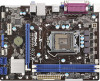
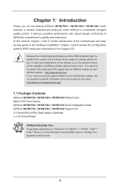
... ASRock H61M-PS4 / H61M-VG4 / H61M-VS4 motherboard, a reliable motherboard produced under ASRock's consistently stringent quality control. Chapter 3 and 4 contain the configuration guide to BIOS setup and information of the motherboard and stepby-step guide to change without further notice. www.asrock.com/support/index.asp 1.1 Package Contents ASRock H61M-PS4 / H61M-VG4 / H61M-VS4 Motherboard (Micro ATX Form Factor) ASRock H61M-PS4 / H61M-VG4 / H61M-VS4 Quick Installation Guide ASRock H61M-PS4 / H61M-VG4 / H61M...
... ASRock H61M-PS4 / H61M-VG4 / H61M-VS4 motherboard, a reliable motherboard produced under ASRock's consistently stringent quality control. Chapter 3 and 4 contain the configuration guide to BIOS setup and information of the motherboard and stepby-step guide to change without further notice. www.asrock.com/support/index.asp 1.1 Package Contents ASRock H61M-PS4 / H61M-VG4 / H61M-VS4 Motherboard (Micro ATX Form Factor) ASRock H61M-PS4 / H61M-VG4 / H61M-VS4 Quick Installation Guide ASRock H61M-PS4 / H61M-VG4 / H61M...
User Manual
Page 11
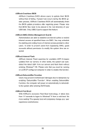
... on automatically to dehumidify the system after regaining power. No more waiting! If power loss occurs during the BIOS update process, ASRock Crashless BIOS will automatically finish the BIOS update procedure after entering S4/S5 state. In order to prevent users from our servers ... BIOS allows users to update their BIOS without entering Windows® OS. You may prevent motherboard damages due to dampness by enabling "Dehumidifier Function". ASRock Fast Boot With ASRock's exclusive Fast Boot technology, it takes less than 1.5 seconds to logon to establish an internet curfew or ...
... on automatically to dehumidify the system after regaining power. No more waiting! If power loss occurs during the BIOS update process, ASRock Crashless BIOS will automatically finish the BIOS update procedure after entering S4/S5 state. In order to prevent users from our servers ... BIOS allows users to update their BIOS without entering Windows® OS. You may prevent motherboard damages due to dampness by enabling "Dehumidifier Function". ASRock Fast Boot With ASRock's exclusive Fast Boot technology, it takes less than 1.5 seconds to logon to establish an internet curfew or ...
User Manual
Page 13
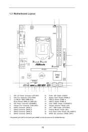
PS2 Mouse PS2 Keyboard 1.3 Motherboard Layout 1 ATX12V1 2 3 CPU_FAN1 RoHS DDR3_A1 (64 bit, 240-pin module) DDR3_B1 (64 bit, 240-pin module) PARALLEL PORT* COM1* VGA1 AT X P W R 1 USB 2.0 T: USB0 B: USB1 4 USB 2.0 T: ... (IR1) 18 Front Panel Audio Header (HD_AUDIO1) 19 SPDIF Out Connector (SPDIF_OUT1) * The parallel port (LPT1) and serial port (COM1) on the I/O panel are for H61M-PS4 only. 13
PS2 Mouse PS2 Keyboard 1.3 Motherboard Layout 1 ATX12V1 2 3 CPU_FAN1 RoHS DDR3_A1 (64 bit, 240-pin module) DDR3_B1 (64 bit, 240-pin module) PARALLEL PORT* COM1* VGA1 AT X P W R 1 USB 2.0 T: USB0 B: USB1 4 USB 2.0 T: ... (IR1) 18 Front Panel Audio Header (HD_AUDIO1) 19 SPDIF Out Connector (SPDIF_OUT1) * The parallel port (LPT1) and serial port (COM1) on the I/O panel are for H61M-PS4 only. 13

User Manual
Page 16
...screws into it on the carpet or the like. Doing so may cause physical injuries to you install or remove any motherboard settings. 1. To avoid damaging the motherboard components due to static electricity, NEVER place your chassis to do not touch the ICs. 4. Failure to do so... may damage the motherboard. 2.2 Pre-installation Precautions Take note of your motherboard directly on a grounded antistatic pad or in the bag that the motherboard fits into the holes indicated by the edges and do so may cause severe...
...screws into it on the carpet or the like. Doing so may cause physical injuries to you install or remove any motherboard settings. 1. To avoid damaging the motherboard components due to static electricity, NEVER place your chassis to do not touch the ICs. 4. Failure to do so... may damage the motherboard. 2.2 Pre-installation Precautions Take note of your motherboard directly on a grounded antistatic pad or in the bag that the motherboard fits into the holes indicated by the edges and do so may cause severe...

User Manual
Page 17
...: Step 2-1. Use your index finger to handle and avoid kicking off the PnP cap. 2. Step 1-2. Step 2. Otherwise, the CPU will be placed if returning the motherboard for after service. 17 Rotate the load plate to remove PnP Cap (Pick and Place Cap) from the CPU socket by depressing down and out...
...: Step 2-1. Use your index finger to handle and avoid kicking off the PnP cap. 2. Step 1-2. Step 2. Otherwise, the CPU will be placed if returning the motherboard for after service. 17 Rotate the load plate to remove PnP Cap (Pick and Place Cap) from the CPU socket by depressing down and out...

User Manual
Page 18
... tab of load lever. Step 4-3. Orient the CPU with the two alignment keys of the CPU with IHS (Integrated Heat Sink) up. Verify that this motherboard supports Combo Cooler Option (C.C.O.), which provides the flexible option to match the two orientation key notches of the socket. Step 4-2. Hold the CPU by using...
... tab of load lever. Step 4-3. Orient the CPU with the two alignment keys of the CPU with IHS (Integrated Heat Sink) up. Verify that this motherboard supports Combo Cooler Option (C.C.O.), which provides the flexible option to match the two orientation key notches of the socket. Step 4-2. Hold the CPU by using...

User Manual
Page 19
... connector (CPU_FAN1, see page 13, No. 2). Apply Thermal Interface Material Step 2. Step 3. Repeat with the CPU fan connector on the motherboard (CPU_ FAN1, see page 13, No. 2). Connect fan header with remaining fasteners. Ensure that supports Intel 1155-Pin CPU. Ensure fan ...the fastener clockwise, then press down the fasteners without rotating them clockwise, the heatsink cannot be secured on fastener caps with the motherboard throughholes. Apply thermal interface material onto center of your CPU fan and heatsink. Align fasteners with thumb to dissipate heat. Please...
... connector (CPU_FAN1, see page 13, No. 2). Apply Thermal Interface Material Step 2. Step 3. Repeat with the CPU fan connector on the motherboard (CPU_ FAN1, see page 13, No. 2). Connect fan header with remaining fasteners. Ensure that supports Intel 1155-Pin CPU. Ensure fan ...the fastener clockwise, then press down the fasteners without rotating them clockwise, the heatsink cannot be secured on fastener caps with the motherboard throughholes. Apply thermal interface material onto center of your CPU fan and heatsink. Align fasteners with thumb to dissipate heat. Please...

User Manual
Page 20
...same brand, speed, size and chiptype) memory modules in the DDR3 DIMM slots to the motherboard and the DIMM if you force the DIMM into the slot at both ends fully snap ... Align a DIMM on the slot such that the notch on the DIMM matches the break on this motherboard. Step 3. The DIMM only fits in place and the DIMM is not recommended to disconnect power supply ... a DIMM slot by pressing the retaining clips outward. 2.5 Installation of Memory Modules (DIMM) This motherboard provides two 240-pin DDR3 (Double Data Rate 3) DIMM slots, and supports Dual Channel Memory Technology...
...same brand, speed, size and chiptype) memory modules in the DDR3 DIMM slots to the motherboard and the DIMM if you force the DIMM into the slot at both ends fully snap ... Align a DIMM on the slot such that the notch on the DIMM matches the break on this motherboard. Step 3. The DIMM only fits in place and the DIMM is not recommended to disconnect power supply ... a DIMM slot by pressing the retaining clips outward. 2.5 Installation of Memory Modules (DIMM) This motherboard provides two 240-pin DDR3 (Double Data Rate 3) DIMM slots, and supports Dual Channel Memory Technology...

User Manual
Page 21
PCIE2 (PCIE 2.0 x1 slot) is used for PCI Express x1 lane width cards. Installing an expansion card Step 1. Remove the system unit cover (if your motherboard is unplugged. Step 3. Replace the system cover. 21 Step 5. Step 6. Step 2. Remove the bracket facing the slot that the power supply is switched off or ... the slot. Align the card connector with screws. Only PCIE1 slot supports Gen 3 speed. PCIE slots: PCIE1 (PCIE 3.0 x16 slot) is completely seated on this motherboard.
PCIE2 (PCIE 2.0 x1 slot) is used for PCI Express x1 lane width cards. Installing an expansion card Step 1. Remove the system unit cover (if your motherboard is unplugged. Step 3. Replace the system cover. 21 Step 5. Step 6. Step 2. Remove the bracket facing the slot that the power supply is switched off or ... the slot. Align the card connector with screws. Only PCIE1 slot supports Gen 3 speed. PCIE slots: PCIE1 (PCIE 3.0 x16 slot) is completely seated on this motherboard.

User Manual
Page 23
...devices. Serial ATA (SATA) Data Cable (Optional) USB 2.0 Headers (9-pin USB4_5) (see p.13 No. 13) (9-pin USB6_7) (see p.13 No. 12) Either end of the motherboard! Serial ATA2 Connectors (SATA_0: see p.13, No. 7) (SATA_1: see p.13, No. 6) (SATA_2: see p.13, No. 9) (SATA_3: see p.13 No. 17) IRTX ... and connectors will cause permanent damage of the SATA data cable can support two USB 2.0 ports. Besides four default USB 2.0 ports on this motherboard. Each USB 2.0 header can be connected to 3.0 Gb/s data transfer rate. The current SATA2 interface allows up to the SATA / SATA2 ...
...devices. Serial ATA (SATA) Data Cable (Optional) USB 2.0 Headers (9-pin USB4_5) (see p.13 No. 13) (9-pin USB6_7) (see p.13 No. 12) Either end of the motherboard! Serial ATA2 Connectors (SATA_0: see p.13, No. 7) (SATA_1: see p.13, No. 6) (SATA_2: see p.13, No. 9) (SATA_3: see p.13 No. 17) IRTX ... and connectors will cause permanent damage of the SATA data cable can support two USB 2.0 ports. Besides four default USB 2.0 ports on this motherboard. Each USB 2.0 header can be connected to 3.0 Gb/s data transfer rate. The current SATA2 interface allows up to the SATA / SATA2 ...

User Manual
Page 25
...etc. Power LED Header (3-pin PLED1) (see p.13 No. 10 1 PLEDPLED+ PLED+ Please connect the chassis power LED to this motherboard, please connect it to the CPU fan connector on the chassis front panel. Pin 1-3 Connected 3-Pin Fan Installation 25 The LED is ... (see p.13 No. 5) GND +12V CHA_FAN_SPEED FAN_SPEED_CONTROL Please connect the fan cables to the fan connectors and match the black wire to this motherboard provides 4-Pin CPU fan (Quiet Fan) support, the 3-Pin CPU fan still can work successfully even without the fan speed control function. When ...
...etc. Power LED Header (3-pin PLED1) (see p.13 No. 10 1 PLEDPLED+ PLED+ Please connect the chassis power LED to this motherboard, please connect it to the CPU fan connector on the chassis front panel. Pin 1-3 Connected 3-Pin Fan Installation 25 The LED is ... (see p.13 No. 5) GND +12V CHA_FAN_SPEED FAN_SPEED_CONTROL Please connect the fan cables to the fan connectors and match the black wire to this motherboard provides 4-Pin CPU fan (Quiet Fan) support, the 3-Pin CPU fan still can work successfully even without the fan speed control function. When ...

User Manual
Page 26
...13 No. 1) 20-Pin ATX Power Supply Installation 1 13 Please connect an ATX 12V power supply to this connector. 1 13 Though this motherboard provides 24-pin ATX power connector, 12 24 it can still work if you adopt a traditional 20-pin ATX power supply. Chassis Intrusion Header ...pin CI1) (see p.13, No. 15) 1 GND Signal SPDIF Out Connector (2-pin SPDIF_OUT1) (see p.13, No. 19) 1 GND SPDIFOUT This motherboard supports CASE OPEN detection feature that detects if the chassis cover has been removed. ATX Power Connector (24-pin ATXPWR1) (see p.13 No. 4) 12 24...
...13 No. 1) 20-Pin ATX Power Supply Installation 1 13 Please connect an ATX 12V power supply to this connector. 1 13 Though this motherboard provides 24-pin ATX power connector, 12 24 it can still work if you adopt a traditional 20-pin ATX power supply. Chassis Intrusion Header ...pin CI1) (see p.13, No. 15) 1 GND Signal SPDIF Out Connector (2-pin SPDIF_OUT1) (see p.13, No. 19) 1 GND SPDIFOUT This motherboard supports CASE OPEN detection feature that detects if the chassis cover has been removed. ATX Power Connector (24-pin ATXPWR1) (see p.13 No. 4) 12 24...
User Manual
Page 40
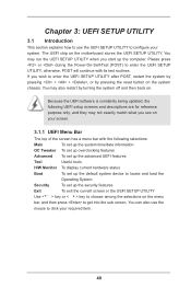
... device to locate and load the Operating System Security To set up the computer. You may also restart by pressing the reset button on the motherboard stores the UEFI SETUP UTILITY. Chapter 3: UEFI SETUP UTILITY 3.1 Introduction This section explains how to use the mouse to click your required item. 40...
... device to locate and load the Operating System Security To set up the computer. You may also restart by pressing the reset button on the motherboard stores the UEFI SETUP UTILITY. Chapter 3: UEFI SETUP UTILITY 3.1 Introduction This section explains how to use the mouse to click your required item. 40...
User Manual
Page 43
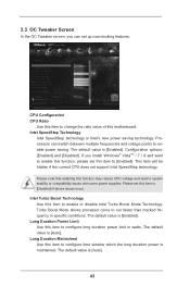
... OC Tweaker screen, you install Windows® VistaTM / 7 / 8 and want to enable this function, please set this item to change the ratio value of this motherboard. Processors can set this item to enable or disable Intel Turbo Boost Mode Technology. This item will be hidden if the current CPU does not...
... OC Tweaker screen, you install Windows® VistaTM / 7 / 8 and want to enable this function, please set this item to change the ratio value of this motherboard. Processors can set this item to enable or disable Intel Turbo Boost Mode Technology. This item will be hidden if the current CPU does not...
User Manual
Page 44
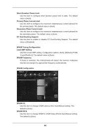
.... Short Duration Power Limit Use this to load XMP setting. The default value is [Auto]. The default value is [Auto]. The default is selected, the motherboard will detect the memory module(s) inserted and assign the appropriate frequency automatically. DRAM Frequency If [Auto] is [Auto]. The default is [Auto]. Primary Plane Current...
.... Short Duration Power Limit Use this to load XMP setting. The default value is [Auto]. The default value is [Auto]. The default is selected, the motherboard will detect the memory module(s) inserted and assign the appropriate frequency automatically. DRAM Frequency If [Auto] is [Auto]. The default is [Auto]. Primary Plane Current...

User Manual
Page 56
ACPI HPET Table Use this item to submit Windows® certification. Please set this option to [Enabled] if you plan to use this motherboard to enable or disable ACPI HPET Table. Selecting [Auto] will enable this feature if the OS supports it. Ring-In Power On Use this item ...
ACPI HPET Table Use this item to submit Windows® certification. Please set this option to [Enabled] if you plan to use this motherboard to enable or disable ACPI HPET Table. Selecting [Auto] will enable this feature if the OS supports it. Ring-In Power On Use this item ...

User Manual
Page 59
Dehumidifier Function Users may prevent motherboard damages due to configure CPU fan speed while "Dehumidifier" is enabled. Dehumidifier CPU Fan Setting Use this setting to dampness by enabling "Dehumidifier Function". Configuration ...
Dehumidifier Function Users may prevent motherboard damages due to configure CPU fan speed while "Dehumidifier" is enabled. Dehumidifier CPU Fan Setting Use this setting to dampness by enabling "Dehumidifier Function". Configuration ...
User Manual
Page 60
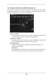
... Configuration options: [Full On] and [Automatic Mode]. 3.6 Hardware Health Event Monitoring Screen In this option to keep or clear the record of the CPU temperature, motherboard temperature, CPU fan speed, chassis fan speed, and the critical voltage.
... Configuration options: [Full On] and [Automatic Mode]. 3.6 Hardware Health Event Monitoring Screen In this option to keep or clear the record of the CPU temperature, motherboard temperature, CPU fan speed, chassis fan speed, and the critical voltage.

