User Manual
Page 2
... may not cause harmful interference, and (2) this device must accept any errors or omissions that may cause undesired operation. ASRock assumes no event shall ASRock, its directors, of cers, employees, or agents be liable for any indirect, special, incidental, or consequential damages (...BMP) regulations passed by the California Legislature. CALIFORNIA, USA ONLY The Lithium battery adopted on this motherboard contains Perchlorate, a toxic substance controlled in this manual, ASRock does not provide warranty of any kind, either expressed or implied, including but not limited to infringe...
... may not cause harmful interference, and (2) this device must accept any errors or omissions that may cause undesired operation. ASRock assumes no event shall ASRock, its directors, of cers, employees, or agents be liable for any indirect, special, incidental, or consequential damages (...BMP) regulations passed by the California Legislature. CALIFORNIA, USA ONLY The Lithium battery adopted on this motherboard contains Perchlorate, a toxic substance controlled in this manual, ASRock does not provide warranty of any kind, either expressed or implied, including but not limited to infringe...

User Manual
Page 3
... 5 1.2 Specifications 6 1.3 Motherboard Layout 12 1.4 I/O Panel 13 2 Installation 14 2.1 Screw Holes 14 2.2 Pre-installation Precautions 14 2.3 CPU Installation 15 2.4 Installation of Heatsink and CPU fan 17 2.5 Installation of Memory Modules (DIMM 18 2.6 Expansion Slots (PCI and PCI Express Slots 19 2.7 Dual Monitor and Surround Display Features 20 2.8 ASRock Smart Remote Installation...
... 5 1.2 Specifications 6 1.3 Motherboard Layout 12 1.4 I/O Panel 13 2 Installation 14 2.1 Screw Holes 14 2.2 Pre-installation Precautions 14 2.3 CPU Installation 15 2.4 Installation of Heatsink and CPU fan 17 2.5 Installation of Memory Modules (DIMM 18 2.6 Expansion Slots (PCI and PCI Express Slots 19 2.7 Dual Monitor and Surround Display Features 20 2.8 ASRock Smart Remote Installation...

User Manual
Page 5
It delivers excellent performance with robust design conforming to ASRock's commitment to the "User Manual" in our support CD for purchasing ASRock H61M/U3S3 motherboard, a reliable motherboard produced under ASRock's consistently stringent quality control. www.asrock.com/support/index.asp 1.1 Package Contents ASRock H61M/U3S3 Motherboard (Micro ATX Form Factor: 9.6-in x 8.6-in Storage Con guration to AHCI mode. To get better performance in...
It delivers excellent performance with robust design conforming to ASRock's commitment to the "User Manual" in our support CD for purchasing ASRock H61M/U3S3 motherboard, a reliable motherboard produced under ASRock's consistently stringent quality control. www.asrock.com/support/index.asp 1.1 Package Contents ASRock H61M/U3S3 Motherboard (Micro ATX Form Factor: 9.6-in x 8.6-in Storage Con guration to AHCI mode. To get better performance in...

User Manual
Page 9
... le system. 9 Your friends then can choose to change. Please check Intel® website for proper installation. 3. This motherboard supports Dual Channel Memory Technology. ASRock Extreme Tuning Utility (AXTU) is no such limitation. 4. In Overclocking, you implement Dual Channel Memory Technology, make sure to...", please check page 41. 2. Besides, with 64-bit CPU, there is an all-in-one tool to access ASRock Instant Flash. ASRock website: http://www.asrock.com 8. About the setting of memory modules on page 18 for the latest information. 5. For Windows® OS with...
... le system. 9 Your friends then can choose to change. Please check Intel® website for proper installation. 3. This motherboard supports Dual Channel Memory Technology. ASRock Extreme Tuning Utility (AXTU) is no such limitation. 4. In Overclocking, you implement Dual Channel Memory Technology, make sure to...", please check page 41. 2. Besides, with 64-bit CPU, there is an all-in-one tool to access ASRock Instant Flash. ASRock website: http://www.asrock.com 8. About the setting of memory modules on page 18 for the latest information. 5. For Windows® OS with...

User Manual
Page 10
... to your real-time newsfeed into Standby mode (S1), Suspend to install the ASRock AIWI utility either from ASRock of internet browser, is the smart start experiencing the exciting motion controlled games. ASRock motherboards are exclusively equipped with the SmartView utility that not all the 775 and 1156... to turn your computer and up -do not forget to pay attention to your motherboard, and also download the free AIWI Lite from your iPhone/iPod touch as iPhone/iPod/iPad Touch, ASRock has prepared a wonderful solution for a more personal Internet experience. While CPU overheat is...
... to your real-time newsfeed into Standby mode (S1), Suspend to install the ASRock AIWI utility either from ASRock of internet browser, is the smart start experiencing the exciting motion controlled games. ASRock motherboards are exclusively equipped with the SmartView utility that not all the 775 and 1156... to turn your computer and up -do not forget to pay attention to your motherboard, and also download the free AIWI Lite from your iPhone/iPod touch as iPhone/iPod/iPad Touch, ASRock has prepared a wonderful solution for a more personal Internet experience. While CPU overheat is...

User Manual
Page 11
... completed system shall be under 100 mA current consumption. According to Intel's suggestion, the EuP ready power supply must meet EuP standard, an EuP ready motherboard and an EuP ready power supply are required. According to de ne the power consumption for more details. 11 For EuP ready power supply selection...
... completed system shall be under 100 mA current consumption. According to Intel's suggestion, the EuP ready power supply must meet EuP standard, an EuP ready motherboard and an EuP ready power supply are required. According to de ne the power consumption for more details. 11 For EuP ready power supply selection...

User Manual
Page 12
1.3 Motherboard Layout 1 2 21.8cm (8.6 in) 3 4 5 6 ErP/EuP Ready CPU_FAN1 ATX12V1 1 SPEAKER1 PS2 Mouse PS2 Keyboard ATXPWR1 24.4cm (9.6 in) DDR3 DDR3_B1 (64 bit, 240-pin module) ... 3.0 T: USB2 B: USB3 USB 2.0 T: USB4 Top: B: USB5 RJ-45 RoHS CMOS Battery PCI Express 2.0 Top: LINE IN Center: FRONT Bottom: MIC IN 28 LAN PHY PCIE1 H61M/U3S3 PCI1 27 26 HD_AUDIO1 1 PCI2 25 AUDIO CODEC 1 LPT1 PCIE2 COM1 1 Super I/O Dual Channel DX10.1 SATA3_0 SATA3_1 CHA_FAN1 Intel H61 32Mb BIOS SATA2_0 1 CLRCMOS1 IR1...
1.3 Motherboard Layout 1 2 21.8cm (8.6 in) 3 4 5 6 ErP/EuP Ready CPU_FAN1 ATX12V1 1 SPEAKER1 PS2 Mouse PS2 Keyboard ATXPWR1 24.4cm (9.6 in) DDR3 DDR3_B1 (64 bit, 240-pin module) ... 3.0 T: USB2 B: USB3 USB 2.0 T: USB4 Top: B: USB5 RJ-45 RoHS CMOS Battery PCI Express 2.0 Top: LINE IN Center: FRONT Bottom: MIC IN 28 LAN PHY PCIE1 H61M/U3S3 PCI1 27 26 HD_AUDIO1 1 PCI2 25 AUDIO CODEC 1 LPT1 PCIE2 COM1 1 Super I/O Dual Channel DX10.1 SATA3_0 SATA3_1 CHA_FAN1 Intel H61 32Mb BIOS SATA2_0 1 CLRCMOS1 IR1...

User Manual
Page 14
...cause physical injuries to the chassis. Unplug the power cord from the power supply. Hold components by circles to secure the motherboard to you uninstall any component, place it . Chapter 2: Installation This is detached from the wall socket before touching any ...a Micro ATX form factor (9.6" x 8.6", 24.4 x 21.8 cm) motherboard. Before you install the motherboard, study the con guration of the following precautions before installing or removing the motherboard. Failure to the motherboard, peripherals, and/or components. 14 Before you handle components. 3. Doing so...
...cause physical injuries to the chassis. Unplug the power cord from the power supply. Hold components by circles to secure the motherboard to you uninstall any component, place it . Chapter 2: Installation This is detached from the wall socket before touching any ...a Micro ATX form factor (9.6" x 8.6", 24.4 x 21.8 cm) motherboard. Before you install the motherboard, study the con guration of the following precautions before installing or removing the motherboard. Failure to the motherboard, peripherals, and/or components. 14 Before you handle components. 3. Doing so...

User Manual
Page 15
... retention tab. Step 1-2. Step 1-3. Step 1. Step 2. Open the socket: Step 1-1. This cap must be seriously damaged. Otherwise, the CPU will be placed if returning the motherboard for after service. 15
... retention tab. Step 1-2. Step 1-3. Step 1. Step 2. Open the socket: Step 1-1. This cap must be seriously damaged. Otherwise, the CPU will be placed if returning the motherboard for after service. 15
User Manual
Page 17
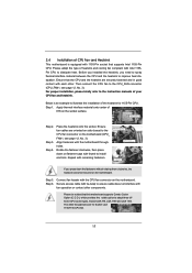
...to install and lock. Rotate the fastener clockwise, then press down the fasteners without rotating them clockwise, the heatsink cannot be noticed that this motherboard supports Combo Cooler Option (C.C.O.), which provides the exible option to adopt three different CPU cooler types, Socket LGA 775, LGA 1155 and LGA ...1156. 2.4 Installation of CPU Fan and Heatsink This motherboard is an example to illustrate the installation of the heatsink for Socket LGA 1155/1156 CPU fan. 17 Ensure that supports Intel 1155-Pin...
...to install and lock. Rotate the fastener clockwise, then press down the fasteners without rotating them clockwise, the heatsink cannot be noticed that this motherboard supports Combo Cooler Option (C.C.O.), which provides the exible option to adopt three different CPU cooler types, Socket LGA 775, LGA 1155 and LGA ...1156. 2.4 Installation of CPU Fan and Heatsink This motherboard is an example to illustrate the installation of the heatsink for Socket LGA 1155/1156 CPU fan. 17 Ensure that supports Intel 1155-Pin...

User Manual
Page 18
... memory module into the slot until the retaining clips at both ends fully snap back in place and the DIMM is not recommended to the motherboard and the DIMM if you force the DIMM into the slot at single channel mode. 1. Align a DIMM on the slot such that the ...notch on the DIMM matches the break on the slot. 2.5 Installation of Memory Modules (DIMM) This motherboard provides two 240-pin DDR3 (Double Data Rate 3) DIMM slots, and supports Dual Channel Memory Technology. Installing a DIMM Please make sure to activate Dual Channel...
... memory module into the slot until the retaining clips at both ends fully snap back in place and the DIMM is not recommended to the motherboard and the DIMM if you force the DIMM into the slot at single channel mode. 1. Align a DIMM on the slot such that the ...notch on the DIMM matches the break on the slot. 2.5 Installation of Memory Modules (DIMM) This motherboard provides two 240-pin DDR3 (Double Data Rate 3) DIMM slots, and supports Dual Channel Memory Technology. Installing a DIMM Please make sure to activate Dual Channel...

User Manual
Page 19
... PCI Express x16 lane width graphics cards. Step 3. Step 5. PCIE2 (PCIE x1 slot; Step 6. Remove the system unit cover (if your motherboard is unplugged. Replace the system cover. 19 Step 4. Align the card connector with screws. Please read the documentation of the expansion card and make... sure that you start the installation. White) is completely seated on this motherboard. Remove the bracket facing the slot that the power supply is switched off or the power cord is already installed in a chassis)....
... PCI Express x16 lane width graphics cards. Step 3. Step 5. PCIE2 (PCIE x1 slot; Step 6. Remove the system unit cover (if your motherboard is unplugged. Replace the system cover. 19 Step 4. Align the card connector with screws. Please read the documentation of the expansion card and make... sure that you start the installation. White) is completely seated on this motherboard. Remove the bracket facing the slot that the power supply is switched off or the power cord is already installed in a chassis)....

User Manual
Page 20
...Sub, DVI-D and HDMI monitors cannot be enabled at the same time. To enable dual monitor feature, please follow the below steps: 1. This motherboard also provides independent display controllers for DVI-D, D-Sub and HDMI to HDMI port on VGA card to your system and restart your computer. 2.7 Dual ...Monitor and Surround Display Features Dual Monitor Feature This motherboard supports dual monitor feature. If you haven't installed onboard VGA driver yet, please install onboard VGA driver from our support CD to your...
...Sub, DVI-D and HDMI monitors cannot be enabled at the same time. To enable dual monitor feature, please follow the below steps: 1. This motherboard also provides independent display controllers for DVI-D, D-Sub and HDMI to HDMI port on VGA card to your system and restart your computer. 2.7 Dual ...Monitor and Surround Display Features Dual Monitor Feature This motherboard supports dual monitor feature. If you haven't installed onboard VGA driver yet, please install onboard VGA driver from our support CD to your...

User Manual
Page 21
... display icon and select "Attached", if necessary. Then connect other monitor cables to install them again. 5. Surround Display Feature This motherboard supports surround display upgrade. Select the display icon identi ed by the number one monitor will always be Primary, and all additional monitors...Express VGA cards, you use multiple monitors with your primary monitor, and then select "Primary". Click "Extend my Windows desktop onto this motherboard. 4. With the internal VGA output support (DVI-D, D-Sub and HDMI) and external add-on PCIE1 slot. 3. When you can adjust...
... display icon and select "Attached", if necessary. Then connect other monitor cables to install them again. 5. Surround Display Feature This motherboard supports surround display upgrade. Select the display icon identi ed by the number one monitor will always be Primary, and all additional monitors...Express VGA cards, you use multiple monitors with your primary monitor, and then select "Primary". Click "Extend my Windows desktop onto this motherboard. 4. With the internal VGA output support (DVI-D, D-Sub and HDMI) and external add-on PCIE1 slot. 3. When you can adjust...

User Manual
Page 22
..., DVD player or set -top-boxes, as well as few entertainment PCs requires a secure connection to use HDCP function with this motherboard. such as it is highly recommended that the HDTV or LCD monitor you can adjust the parameters of intercepting digital data midstream between...representing the physical setup of content as a monitor, television or projector. HDCP Function HDCP function is HDCP? What is supported on this motherboard, you would like to a compliant display. HDCP is designed to protect the integrity of your change. such as well. Products compatible ...
..., DVD player or set -top-boxes, as well as few entertainment PCs requires a secure connection to use HDCP function with this motherboard. such as it is highly recommended that the HDTV or LCD monitor you can adjust the parameters of intercepting digital data midstream between...representing the physical setup of content as a monitor, television or projector. HDCP Function HDCP function is HDCP? What is supported on this motherboard, you would like to a compliant display. HDCP is designed to protect the integrity of your change. such as well. Products compatible ...

User Manual
Page 23
...not support Hot-Plug function. Connect the front USB cable to the USB_PWR USB 2.0 header (as below procedures for the motherboard support list: http://www.asrock.com 23 Please do not use the rear USB bracket to the USB 2.0 header on the rear panel. Find the CIR... Multi-Angle CIR Receiver to the other port will remain USB function. 2. Please refer to ASRock website for the quick installation and usage of ASRock motherboards. When the CIR function is only supported by some of ASRock Smart Remote. USB 2.0 header (9-pin, blue) CIR header (4-pin, white) Step2. Please...
...not support Hot-Plug function. Connect the front USB cable to the USB_PWR USB 2.0 header (as below procedures for the motherboard support list: http://www.asrock.com 23 Please do not use the rear USB bracket to the USB 2.0 header on the rear panel. Find the CIR... Multi-Angle CIR Receiver to the other port will remain USB function. 2. Please refer to ASRock website for the quick installation and usage of ASRock motherboards. When the CIR function is only supported by some of ASRock Smart Remote. USB 2.0 header (9-pin, blue) CIR header (4-pin, white) Step2. Please...

User Manual
Page 25
... Gb/s data transfer rate. The current SATA3 interface allows up to the SATA / SATAII / SATA3 hard disk or the SATAII / SATA3 connector on this motherboard. Besides four default USB 2.0 ports on the I/O panel, there are NOT jumpers. Serial ATA (SATA) Data Cable (Optional) USB 2.0 Headers (9-pin ...IR1) (see p.12 No. 21) USB_PWR P-9 P+9 GND DUMMY 1 GND P+8 P-8 USB_PWR IRTX +5VSB DUMMY 1 GND IRRX 25 Either end of the motherboard! Do NOT place jumper caps over the headers and connectors will cause permanent damage of the SATA data cable can support two USB 2.0 ports. This...
... Gb/s data transfer rate. The current SATA3 interface allows up to the SATA / SATAII / SATA3 hard disk or the SATAII / SATA3 connector on this motherboard. Besides four default USB 2.0 ports on the I/O panel, there are NOT jumpers. Serial ATA (SATA) Data Cable (Optional) USB 2.0 Headers (9-pin ...IR1) (see p.12 No. 21) USB_PWR P-9 P+9 GND DUMMY 1 GND P+8 P-8 USB_PWR IRTX +5VSB DUMMY 1 GND IRRX 25 Either end of the motherboard! Do NOT place jumper caps over the headers and connectors will cause permanent damage of the SATA data cable can support two USB 2.0 ports. This...

User Manual
Page 28
... 8-pin ATX 12V power connector, it can work successfully even without the fan speed control function. Though this motherboard provides 4-Pin CPU fan (Quiet Fan) support, the 3-Pin CPU fan still can still work if you adopt a traditional 20-pin ATX power supply. ...pin ATX12V1) (see p.12 No. 7) 12 24 Please connect an ATX power supply to this connector. 1 13 Though this motherboard provides 24-pin ATX power connector, 12 24 it to this motherboard, please connect it can still work if you adopt a traditional 4-pin ATX 12V power supply. Pin 1-3 Connected 3-Pin Fan Installation...
... 8-pin ATX 12V power connector, it can work successfully even without the fan speed control function. Though this motherboard provides 4-Pin CPU fan (Quiet Fan) support, the 3-Pin CPU fan still can still work if you adopt a traditional 20-pin ATX power supply. ...pin ATX12V1) (see p.12 No. 7) 12 24 Please connect an ATX power supply to this connector. 1 13 Though this motherboard provides 24-pin ATX power connector, 12 24 it to this motherboard, please connect it can still work if you adopt a traditional 4-pin ATX 12V power supply. Pin 1-3 Connected 3-Pin Fan Installation...

User Manual
Page 29
...disks into the drive bays of the SATA data cable to the SATA / SATAII hard disk. 2.12 Serial ATA3 (SATA3) Hard Disks Installation This motherboard adopts ASMedia ASM1061 chipset that supports Serial ATA (SATA) / Serial ATAII (SATAII) hard disks. STEP 3: Connect one end of the SATA data ...3: Connect one end of the SATA data cable to install the SATA / SATAII hard disks. You may install SATA / SATAII hard disks on this motherboard for internal storage devices. nector. STEP 4: Connect the other end of your chassis. STEP 2: Connect the SATA power cable to the SATA / SATAII ...
...disks into the drive bays of the SATA data cable to the SATA / SATAII hard disk. 2.12 Serial ATA3 (SATA3) Hard Disks Installation This motherboard adopts ASMedia ASM1061 chipset that supports Serial ATA (SATA) / Serial ATAII (SATAII) hard disks. STEP 3: Connect one end of the SATA data ...3: Connect one end of the SATA data cable to install the SATA / SATAII hard disks. You may install SATA / SATAII hard disks on this motherboard for internal storage devices. nector. STEP 4: Connect the other end of your chassis. STEP 2: Connect the SATA power cable to the SATA / SATAII ...

User Manual
Page 30
... that it cannot perform Hot Plug if the OS has been installed into the SATA / SATAII HDD. 2.14 Hot Plug Function for SATA3 HDDs This motherboard supports Hot Plug function for SATA3 in AHCI mode. NOTE What is Hot Plug Function? 2.13 Hot Plug Function for SATA / SATAII HDDs This...
... that it cannot perform Hot Plug if the OS has been installed into the SATA / SATAII HDD. 2.14 Hot Plug Function for SATA3 HDDs This motherboard supports Hot Plug function for SATA3 in AHCI mode. NOTE What is Hot Plug Function? 2.13 Hot Plug Function for SATA / SATAII HDDs This...

