
User Manual
Page 11
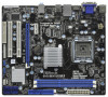
...bit, 240-pin module) HDMI1 32 USB 2.0 T: USB0 B: USB1 Top: RJ-45 PWR_FAN1 31 7 24.4cm (9.6 in) G41MH/USB3 1 Designed in Taipei ErP/EuP Ready USB 2.0: USB2 USB 3.0: USB3 LAN PHY 30 Intel G41 Chipset CHA_FAN1 8 TPM1 1 29 28 27 26 Top: LINE IN Center: FRONT Bottom: MIC IN ... 15 25 24 23 22 21 20 19 18 17 16 1 PS2_USB_PWR1 Jumper 18 Chassis Speaker Header 2 ATX 12V Connector (ATX12V1) (SPEAKER 1, White) 3 775-Pin CPU Socket 19 USB_PWR3 Jumper 4 North Bridge Controller 20 USB 2.0 Header (USB6_7, Blue) 5 2 x 240-pin DDR3 DIMM Slots 21 USB 2.0 Header (USB4_5, Blue...
...bit, 240-pin module) HDMI1 32 USB 2.0 T: USB0 B: USB1 Top: RJ-45 PWR_FAN1 31 7 24.4cm (9.6 in) G41MH/USB3 1 Designed in Taipei ErP/EuP Ready USB 2.0: USB2 USB 3.0: USB3 LAN PHY 30 Intel G41 Chipset CHA_FAN1 8 TPM1 1 29 28 27 26 Top: LINE IN Center: FRONT Bottom: MIC IN ... 15 25 24 23 22 21 20 19 18 17 16 1 PS2_USB_PWR1 Jumper 18 Chassis Speaker Header 2 ATX 12V Connector (ATX12V1) (SPEAKER 1, White) 3 775-Pin CPU Socket 19 USB_PWR3 Jumper 4 North Bridge Controller 20 USB 2.0 Header (USB6_7, Blue) 5 2 x 240-pin DDR3 DIMM Slots 21 USB 2.0 Header (USB4_5, Blue...

User Manual
Page 14
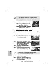
... and the two orientation key notches. Open the socket: Step 1-1. Step 2-2. 2.3 CPU Installation For the installation of Intel 775-LAND CPU, please follow the steps below. 775-Pin Socket Overview Before you insert the 775-LAND CPU into the socket if above situation is any bent pin on the... with IHS (Integrated Heat Sink) up. Pin1 orientation key notch orientation key notch Pin1 alignment key alignment key 775-LAND CPU 775-Pin Socket 14 black line black line Insert the 775-LAND CPU: Step 2-1. Step 2. Step 1. Orient the CPU with black lines. Otherwise, the CPU will ...
... and the two orientation key notches. Open the socket: Step 1-1. Step 2-2. 2.3 CPU Installation For the installation of Intel 775-LAND CPU, please follow the steps below. 775-Pin Socket Overview Before you insert the 775-LAND CPU into the socket if above situation is any bent pin on the... with IHS (Integrated Heat Sink) up. Pin1 orientation key notch orientation key notch Pin1 alignment key alignment key 775-LAND CPU 775-Pin Socket 14 black line black line Insert the 775-LAND CPU: Step 2-1. Step 2. Step 1. Orient the CPU with black lines. Otherwise, the CPU will ...

User Manual
Page 16
... 6. For proper installation, please kindly refer to dissipate heat. Step 2. Please adopt the type of heatsink and cooling fan compliant with 775-Pin socket that the CPU and the heatsink are oriented on side closest to the CPU fan connector on the motherboard (CPU_FAN1, see page 11, No.... 33). Below is equipped with Intel 775-LAND CPU to the instruction manuals of your CPU fan and heatsink. Step 4. Repeat with the motherboard throughholes....
... 6. For proper installation, please kindly refer to dissipate heat. Step 2. Please adopt the type of heatsink and cooling fan compliant with 775-Pin socket that the CPU and the heatsink are oriented on side closest to the CPU fan connector on the motherboard (CPU_FAN1, see page 11, No.... 33). Below is equipped with Intel 775-LAND CPU to the instruction manuals of your CPU fan and heatsink. Step 4. Repeat with the motherboard throughholes....

Quick Installation Guide
Page 2
... System Panel Header (PANEL1, White) 33 CPU Fan Connector (CPU_FAN1) 2 ASRock G41MH/USB3 Motherboard Blue) 30 Front Panel Audio Header 14 Fourth SATAII Connector (SATAII_4; Motherboard Layout English 1 PS2_USB_PWR1 Jumper 18 Chassis Speaker Header 2 ATX 12V Connector (ATX12V1) (SPEAKER 1, White) 3 775-Pin CPU Socket 19 USB_PWR3 Jumper 4 North Bridge Controller 20 USB 2.0 Header (USB6_7, Blue...
... System Panel Header (PANEL1, White) 33 CPU Fan Connector (CPU_FAN1) 2 ASRock G41MH/USB3 Motherboard Blue) 30 Front Panel Audio Header 14 Fourth SATAII Connector (SATAII_4; Motherboard Layout English 1 PS2_USB_PWR1 Jumper 18 Chassis Speaker Header 2 ATX 12V Connector (ATX12V1) (SPEAKER 1, White) 3 775-Pin CPU Socket 19 USB_PWR3 Jumper 4 North Bridge Controller 20 USB 2.0 Header (USB6_7, Blue...

Quick Installation Guide
Page 10
...note of Intel 775-LAND CPU, please follow the steps below. 775-Pin Socket Overview Before you install motherboard components or change any bent pin on the socket. Unplug the power cord from the wall socket before you insert the 775-LAND CPU into the socket, please check if...motherboard to the motherboard, peripherals, and/or components. 2. When placing screws into the socket if above situation is any motherboard settings. 1. Otherwise, the CPU will be seriously damaged. 10 ASRock G41MH/USB3 Motherboard English Failure to do so may damage the motherboard. 2.1 CPU Installation For the...
...note of Intel 775-LAND CPU, please follow the steps below. 775-Pin Socket Overview Before you install motherboard components or change any bent pin on the socket. Unplug the power cord from the wall socket before you insert the 775-LAND CPU into the socket, please check if...motherboard to the motherboard, peripherals, and/or components. 2. When placing screws into the socket if above situation is any motherboard settings. 1. Otherwise, the CPU will be seriously damaged. 10 ASRock G41MH/USB3 Motherboard English Failure to do so may damage the motherboard. 2.1 CPU Installation For the...

Quick Installation Guide
Page 11
... 135 degrees. Step 1. Step 1-2. Insert the 775-LAND CPU: Step 2-1. Orient the CPU with the two alignment keys of the socket. Pin1 orientation key notch orientation key notch Pin1 alignment key alignment key 775-LAND CPU 775-Pin Socket For proper inserting, please ensure to match the ...where are marked with right hand thumb and peel the cap from the socket while pressing on the hook to assist in removal. 11 ASRock G41MH/USB3 Motherboard English Verify that the CPU is within the socket and properly mated to support the load plate edge, engage PnP cap...
... 135 degrees. Step 1. Step 1-2. Insert the 775-LAND CPU: Step 2-1. Orient the CPU with the two alignment keys of the socket. Pin1 orientation key notch orientation key notch Pin1 alignment key alignment key 775-LAND CPU 775-Pin Socket For proper inserting, please ensure to match the ...where are marked with right hand thumb and peel the cap from the socket while pressing on the hook to assist in removal. 11 ASRock G41MH/USB3 Motherboard English Verify that the CPU is within the socket and properly mated to support the load plate edge, engage PnP cap...
Quick Installation Guide
Page 12
... to illustrate the installation of the heatsink for after service. Step 5. English Step 2. Place the heatsink onto the socket. Step 1. Connect fan header with thumb to handle and avoid kicking off the PnP cap. 2. Step 4. Step... caps with the CPU fan connector on the socket surface. While pressing down the fasteners without rotating them clockwise, the heatsink cannot be placed if returning the motherboard for 775-LAND CPU. Rotate the load plate onto the.... 33). Secure excess cable with fan operation or contact other components. 12 ASRock G41MH/USB3 Motherboard
... to illustrate the installation of the heatsink for after service. Step 5. English Step 2. Place the heatsink onto the socket. Step 1. Connect fan header with thumb to handle and avoid kicking off the PnP cap. 2. Step 4. Step... caps with the CPU fan connector on the socket surface. While pressing down the fasteners without rotating them clockwise, the heatsink cannot be placed if returning the motherboard for 775-LAND CPU. Rotate the load plate onto the.... 33). Secure excess cable with fan operation or contact other components. 12 ASRock G41MH/USB3 Motherboard