
User Manual
Page 3
... Holes 13 2.2 Pre-installation Precautions 13 2.3 CPU Installation 14 2.4 Installation of Heatsink and CPU fan 16 2.5 Installation of Memory Modules (DIMM 17 2.6 Expansion Slots (PCI and PCI Express Slots 18 2.7 Dual Monitor Feature 19 2.8 Jumpers Setup 22 2.9 Onboard Headers and Connectors 23 2.10 SATAII Hard Disk Setup Guide 27 2.11 Serial ATA...
... Holes 13 2.2 Pre-installation Precautions 13 2.3 CPU Installation 14 2.4 Installation of Heatsink and CPU fan 16 2.5 Installation of Memory Modules (DIMM 17 2.6 Expansion Slots (PCI and PCI Express Slots 18 2.7 Dual Monitor Feature 19 2.8 Jumpers Setup 22 2.9 Onboard Headers and Connectors 23 2.10 SATAII Hard Disk Setup Guide 27 2.11 Serial ATA...
User Manual
Page 6
Supports Untied Overclocking Technology (see CAUTION 5) - 1 x PCI Express x16 slot - 1 x PCI Express x1 slot - 2 x PCI slots - capacity of system memory: 8GB (see CAUTION 2) - Intel® Graphics Media Accelerator X4500 - Supports Full HD 1080p Blu-ray (BD) / HD-DVD playback with ...
Supports Untied Overclocking Technology (see CAUTION 5) - 1 x PCI Express x16 slot - 1 x PCI Express x1 slot - 2 x PCI slots - capacity of system memory: 8GB (see CAUTION 2) - Intel® Graphics Media Accelerator X4500 - Supports Full HD 1080p Blu-ray (BD) / HD-DVD playback with ...

User Manual
Page 11
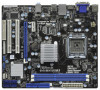
...TPM1) 24 Floppy Connector (FLOPPY1) 8 Chassis Fan Connector (CHA_FAN1) 25 Serial Port Connector (COM1) 9 IDE1 Connector (IDE1, Blue) 26 PCI Slots (PCI1- 2) 10 BIOS SPI Chip 27 PCI Express x16 Slot (PCIE2) 11 South Bridge Controller 28 Internal Audio Connector: CD1 (Black) 12 Clear CMOS Jumper (CLRCMOS1) 29...240-pin module) HDMI1 32 USB 2.0 T: USB0 B: USB1 Top: RJ-45 PWR_FAN1 31 7 24.4cm (9.6 in) G41MH/USB3 1 Designed in Taipei ErP/EuP Ready USB 2.0: USB2 USB 3.0: USB3 LAN PHY 30 Intel G41 Chipset CHA_FAN1 8 TPM1 1 29 28 27 26 Top: LINE IN Center: FRONT Bottom: MIC ...
...TPM1) 24 Floppy Connector (FLOPPY1) 8 Chassis Fan Connector (CHA_FAN1) 25 Serial Port Connector (COM1) 9 IDE1 Connector (IDE1, Blue) 26 PCI Slots (PCI1- 2) 10 BIOS SPI Chip 27 PCI Express x16 Slot (PCIE2) 11 South Bridge Controller 28 Internal Audio Connector: CD1 (Black) 12 Clear CMOS Jumper (CLRCMOS1) 29...240-pin module) HDMI1 32 USB 2.0 T: USB0 B: USB1 Top: RJ-45 PWR_FAN1 31 7 24.4cm (9.6 in) G41MH/USB3 1 Designed in Taipei ErP/EuP Ready USB 2.0: USB2 USB 3.0: USB3 LAN PHY 30 Intel G41 Chipset CHA_FAN1 8 TPM1 1 29 28 27 26 Top: LINE IN Center: FRONT Bottom: MIC ...

User Manual
Page 18
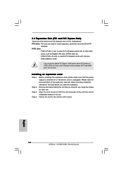
...card connector with the slot and press firmly until the card is unplugged. PCI slots: PCI slots are 2 PCI slots and 2 PCI Express slots on the slot. Before installing the expansion card, please make necessary hardware settings for PCI Express cards with x16 lane width graphics cards. Fasten the card to ... etc. DVI-D and HDMI ports will be enabled. Installing an expansion card Step 1. Remove the bracket facing the slot that have the 32-bit PCI interface. Step 2. PCIE slots: PCIE1 (PCIE x1 slot) is used for the card before you intend to PCIE2 (PCIE x16 slot), only D-Sub...
...card connector with the slot and press firmly until the card is unplugged. PCI slots: PCI slots are 2 PCI slots and 2 PCI Express slots on the slot. Before installing the expansion card, please make necessary hardware settings for PCI Express cards with x16 lane width graphics cards. Fasten the card to ... etc. DVI-D and HDMI ports will be enabled. Installing an expansion card Step 1. Remove the bracket facing the slot that have the 32-bit PCI interface. Step 2. PCIE slots: PCIE1 (PCIE x1 slot) is used for the card before you intend to PCIE2 (PCIE x16 slot), only D-Sub...
User Manual
Page 28
... overclocking risk before you install can work properly. 2.13 Untied Overclocking Technology This motherboard supports Untied Overclocking Technology, which means during overclocking, but PCI / PCIE buses are in the fixed mode so that supports Serial ATA (SATA) / Serial ATAII (SATAII) hard disks. STEP 2: Connect...Guide To install the drivers to your chassis. STEP 4: Connect the other end of your system, please insert the support CD to fixed PCI / PCIE buses. Therefore, the drivers you apply Untied Overclocking Technology. 28 Please follow the order from [Auto] to the warning on ...
... overclocking risk before you install can work properly. 2.13 Untied Overclocking Technology This motherboard supports Untied Overclocking Technology, which means during overclocking, but PCI / PCIE buses are in the fixed mode so that supports Serial ATA (SATA) / Serial ATAII (SATAII) hard disks. STEP 2: Connect...Guide To install the drivers to your chassis. STEP 4: Connect the other end of your system, please insert the support CD to fixed PCI / PCIE buses. Therefore, the drivers you apply Untied Overclocking Technology. 28 Please follow the order from [Auto] to the warning on ...

User Manual
Page 38
... DRAM DLL SKEW Configuration Fixed Mode Operation [Enabled] Intelligent Energy Saver Primary Graphics Adapter Shared Memory PAVP Mode DVMT Mode Select DVMT/FIXED Memory [Disabled] [PCI] [Auto] [Disabled] [DVMT Mode] [Maximum DVMT] Onboard HD Audio Front Panel OnBoard Lan [Auto] [Auto] [Enabled] +F1 F9 F10 ESC Select Screen Select Item Change...
... DRAM DLL SKEW Configuration Fixed Mode Operation [Enabled] Intelligent Energy Saver Primary Graphics Adapter Shared Memory PAVP Mode DVMT Mode Select DVMT/FIXED Memory [Disabled] [PCI] [Auto] [Disabled] [DVMT Mode] [Maximum DVMT] Onboard HD Audio Front Panel OnBoard Lan [Auto] [Auto] [Enabled] +F1 F9 F10 ESC Select Screen Select Item Change...

User Manual
Page 41
... The default value is [Auto]. Configuration options: [Enabled] and [Disabled]. Besides the BIOS option, you to select [Onboard], [PCI] or [PCI Express] as the boot graphic adapter priority. Primary Graphics Adapter This allows you can also choose our Intelligent Energy Saver utility to set...CTRL2 SKEW. The default value is [Enabled]. The default value is [Auto]. Intelligent Energy Saver Intelligent Energy Saver is [PCI]. The default value is a revolutionary technology that delivers unparalleled power savings. Configuration options: [Disabled] and [Lite]. Share ...
... The default value is [Auto]. Configuration options: [Enabled] and [Disabled]. Besides the BIOS option, you to select [Onboard], [PCI] or [PCI Express] as the boot graphic adapter priority. Primary Graphics Adapter This allows you can also choose our Intelligent Energy Saver utility to set...CTRL2 SKEW. The default value is [Enabled]. The default value is [Auto]. Intelligent Energy Saver Intelligent Energy Saver is [PCI]. The default value is a revolutionary technology that delivers unparalleled power savings. Configuration options: [Disabled] and [Lite]. Share ...

User Manual
Page 42
... Configuration options: [128MB], [256MB] and [Maximum DVMT]. This item will not be used under Windows® VistaTM OS because the driver will be disabled when PCI Sound Card is an architecture that offers breakthrough performance for running graphics applications and is [DVMT Mode]. If you to adjust DVMT mode. The option...
... Configuration options: [128MB], [256MB] and [Maximum DVMT]. This item will not be used under Windows® VistaTM OS because the driver will be disabled when PCI Sound Card is an architecture that offers breakthrough performance for running graphics applications and is [DVMT Mode]. If you to adjust DVMT mode. The option...

User Manual
Page 43
...system from the power-soft-off mode. Select [Auto] will enable this item to select whether to submit Windows® VistaTM certification. 43 PCI Devices Power On Use this motherboard to auto-detect or disable the Suspend-toRAM feature. The default value is selected, the AC/Power resumes... recovers. ACPI HPET Table Use this item to enable or disable RTC (Real Time Clock) to turn on AC/Power Loss Ring-In Power On PCI Devices Power On PS / 2 Keyboard Power On RTC Alarm Power On ACPI HPET Table [Disabled] [Power Off] [Disabled] [Disabled] [Disabled] [Disabled] [...
...system from the power-soft-off mode. Select [Auto] will enable this item to select whether to submit Windows® VistaTM certification. 43 PCI Devices Power On Use this motherboard to auto-detect or disable the Suspend-toRAM feature. The default value is selected, the AC/Power resumes... recovers. ACPI HPET Table Use this item to enable or disable RTC (Real Time Clock) to turn on AC/Power Loss Ring-In Power On PCI Devices Power On PS / 2 Keyboard Power On RTC Alarm Power On ACPI HPET Table [Disabled] [Power Off] [Disabled] [Disabled] [Disabled] [Disabled] [...

User Manual
Page 46
...this item to keep the default value unless the installed PCI expansion cards' specifications require other settings. PCI Latency Timer The default value is recommended to enable or disable the PCI IDE BusMaster feature. 46 PCI IDE BusMaster Use this item to enable 32-bit access... the IDE hard disk data transfer rate. 3.4.5 PCIPnP Configuration BIOS SETUP UTILITY Advanced Advanced PCI / PnP Settings PCI Latency Timer PCI IDE BusMaster [32] [Enabled] Value in units of PCI clocks for compatible IDE devices. DMA Mode DMA capability allows the improved transfer-speed and data...
...this item to keep the default value unless the installed PCI expansion cards' specifications require other settings. PCI Latency Timer The default value is recommended to enable or disable the PCI IDE BusMaster feature. 46 PCI IDE BusMaster Use this item to enable 32-bit access... the IDE hard disk data transfer rate. 3.4.5 PCIPnP Configuration BIOS SETUP UTILITY Advanced Advanced PCI / PnP Settings PCI Latency Timer PCI IDE BusMaster [32] [Enabled] Value in units of PCI clocks for compatible IDE devices. DMA Mode DMA capability allows the improved transfer-speed and data...

Quick Installation Guide
Page 2
..., Blue) (Dual Channel: DDR3_A1, DDR3_B1; Blue) 32 USB_PWR2 Jumper 17 System Panel Header (PANEL1, White) 33 CPU Fan Connector (CPU_FAN1) 2 ASRock G41MH/USB3 Motherboard Blue) 22 Infrared Module Header (IR1) 6 ATX Power Connector (ATXPWR1) 23 Print Port Header (LPT1, White) 7 TPM Header (TPM1) ...(FLOPPY1) 8 Chassis Fan Connector (CHA_FAN1) 25 Serial Port Connector (COM1) 9 IDE1 Connector (IDE1, Blue) 26 PCI Slots (PCI1- 2) 10 BIOS SPI Chip 27 PCI Express x16 Slot (PCIE2) 11 South Bridge Controller 28 Internal Audio Connector: CD1 (Black) 12 Clear CMOS Jumper (CLRCMOS1...
..., Blue) (Dual Channel: DDR3_A1, DDR3_B1; Blue) 32 USB_PWR2 Jumper 17 System Panel Header (PANEL1, White) 33 CPU Fan Connector (CPU_FAN1) 2 ASRock G41MH/USB3 Motherboard Blue) 22 Infrared Module Header (IR1) 6 ATX Power Connector (ATXPWR1) 23 Print Port Header (LPT1, White) 7 TPM Header (TPM1) ...(FLOPPY1) 8 Chassis Fan Connector (CHA_FAN1) 25 Serial Port Connector (COM1) 9 IDE1 Connector (IDE1, Blue) 26 PCI Slots (PCI1- 2) 10 BIOS SPI Chip 27 PCI Express x16 Slot (PCIE2) 11 South Bridge Controller 28 Internal Audio Connector: CD1 (Black) 12 Clear CMOS Jumper (CLRCMOS1...

Quick Installation Guide
Page 5
...Codec) - Supports Full HD 1080p Blu-ray (BD) / HD-DVD playback with max. Supports Wake-On-LAN - Supports LAN Cable Detection English 5 ASRock G41MH/USB3 Motherboard Supports FSB1333/1066/800/533 MHz - Supports Hyper-Threading Technology (see CAUTION 4) - Max. Three VGA Output options: D-Sub, DVI-D and HDMI... Supports HDMI Technology with max. resolution up to 2048x1536 @ 60Hz - Southbridge: Intel® ICH7 - shared memory 1759MB (see CAUTION 5) - 1 x PCI Express x16 slot - 1 x PCI Express x1 slot - 2 x PCI slots - capacity of system memory: 8GB (see CAUTION 6) -
...Codec) - Supports Full HD 1080p Blu-ray (BD) / HD-DVD playback with max. Supports Wake-On-LAN - Supports LAN Cable Detection English 5 ASRock G41MH/USB3 Motherboard Supports FSB1333/1066/800/533 MHz - Supports Hyper-Threading Technology (see CAUTION 4) - Max. Three VGA Output options: D-Sub, DVI-D and HDMI... Supports HDMI Technology with max. resolution up to 2048x1536 @ 60Hz - Southbridge: Intel® ICH7 - shared memory 1759MB (see CAUTION 5) - 1 x PCI Express x16 slot - 1 x PCI Express x1 slot - 2 x PCI slots - capacity of system memory: 8GB (see CAUTION 6) -
Quick Installation Guide
Page 14
... start the installation. PCIE slots: PCIE1 (PCIE x1 slot) is unplugged. DVI-D and HDMI ports will be enabled. Keep the screws for PCI Express cards with screws. 14 ASRock G41MH/USB3 Motherboard English Installing an expansion card Step 1. Step 3. Step 4. Align the card connector with the slot and press firmly until the card is...
... start the installation. PCIE slots: PCIE1 (PCIE x1 slot) is unplugged. DVI-D and HDMI ports will be enabled. Keep the screws for PCI Express cards with screws. 14 ASRock G41MH/USB3 Motherboard English Installing an expansion card Step 1. Step 3. Step 4. Align the card connector with the slot and press firmly until the card is...

Quick Installation Guide
Page 23
... option of the SATA data cable to fixed PCI / PCIE buses. Before you install can be auto-detected and listed on the support CD driver page. This section will guide you apply Untied Overclocking Technology. 23 ASRock G41MH/USB3 Motherboard English Therefore, CPU FSB is untied during...other end of your system can work properly. 2.10 Untied Overclocking Technology This motherboard supports Untied Overclocking Technology, which means during overclocking, but PCI / PCIE buses are in the fixed mode so that supports Serial ATA (SATA) / Serial ATAII (SATAII) hard disks. STEP 2: ...
... option of the SATA data cable to fixed PCI / PCIE buses. Before you install can be auto-detected and listed on the support CD driver page. This section will guide you apply Untied Overclocking Technology. 23 ASRock G41MH/USB3 Motherboard English Therefore, CPU FSB is untied during...other end of your system can work properly. 2.10 Untied Overclocking Technology This motherboard supports Untied Overclocking Technology, which means during overclocking, but PCI / PCIE buses are in the fixed mode so that supports Serial ATA (SATA) / Serial ATAII (SATAII) hard disks. STEP 2: ...
