User Manual
Page 3
...1.3 Motherboard Layout 10 1.4 I/O Panel 11 2 Installation 12 2.1 Screw Holes 12 2.2 Pre-installation Precautions 12 2.3 CPU Installation 13 2.4 Installation of Heatsink and CPU fan 15 2.5 Installation of Memory Modules (DIMM 16 2.6 Expansion Slots (PCI and PCI Express Slots 17 2.7 Jumpers... BIOS Menu Bar 26 3.1.2 Navigation Keys 27 3.2 Main Screen 27 3.3 OC Tweaker Screen 28 3.4 Advanced Screen 31 3.4.1 CPU Configuration 32 3.4.2 Chipset Configuration 34 3.4.3 ACPI Configuration 40 3.4.4 Storage Configuration 41 3.4.5 PCIPnP Configuration 43 3.4.6 Floppy Configuration 44 ...
...1.3 Motherboard Layout 10 1.4 I/O Panel 11 2 Installation 12 2.1 Screw Holes 12 2.2 Pre-installation Precautions 12 2.3 CPU Installation 13 2.4 Installation of Heatsink and CPU fan 15 2.5 Installation of Memory Modules (DIMM 16 2.6 Expansion Slots (PCI and PCI Express Slots 17 2.7 Jumpers... BIOS Menu Bar 26 3.1.2 Navigation Keys 27 3.2 Main Screen 27 3.3 OC Tweaker Screen 28 3.4 Advanced Screen 31 3.4.1 CPU Configuration 32 3.4.2 Chipset Configuration 34 3.4.3 ACPI Configuration 40 3.4.4 Storage Configuration 41 3.4.5 PCIPnP Configuration 43 3.4.6 Floppy Configuration 44 ...
User Manual
Page 5
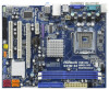
You may find the latest VGA cards and CPU support lists on ASRock website without notice. In this manual, chapter 1 and 2 contain introduction of this manual will be available on ASRock website as well. Because the motherboard specifications and the BIOS ...robust design conforming to ASRock's commitment to quality and endurance. Chapter 1 Introduction Thank you are using. www.asrock.com/support/index.asp 1.1 Package Contents ASRock G41M-S3 Motherboard (Micro ATX Form Factor: 9.6-in x 7.6-in, 24.4 cm x 19.3 cm) ASRock G41M-S3 Quick Installation Guide ASRock G41M-S3 Support CD Two Serial...
You may find the latest VGA cards and CPU support lists on ASRock website without notice. In this manual, chapter 1 and 2 contain introduction of this manual will be available on ASRock website as well. Because the motherboard specifications and the BIOS ...robust design conforming to ASRock's commitment to quality and endurance. Chapter 1 Introduction Thank you are using. www.asrock.com/support/index.asp 1.1 Package Contents ASRock G41M-S3 Motherboard (Micro ATX Form Factor: 9.6-in x 7.6-in, 24.4 cm x 19.3 cm) ASRock G41M-S3 Quick Installation Guide ASRock G41M-S3 Support CD Two Serial...

User Manual
Page 6
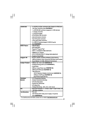
...Core Wolfdale processors - Supports FSB1333/1066/800/533 MHz (see CAUTION 3) - Supports Untied Overclocking Technology (see CAUTION 1) - Supports EM64T CPU - Max. Max. resolution up to -Use USB 2.0 Ports - 1 x RJ-45 LAN Port with max. HD Audio Jack: ...100 Ethernet - Southbridge: Intel® ICH7 - Pixel Shader 4.0, DirectX 10 - Northbridge: Intel® G41 - Realtek PCIE x1 LAN 8103EL / 8102EL - 1.2 Specifications Platform CPU Chipset Memory Expansion Slot Graphics Audio LAN Rear Panel I /O Panel - 1 x PS/2 Mouse Port - 1 x PS/2 Keyboard Port - 1 x Serial Port: COM1 ...
...Core Wolfdale processors - Supports FSB1333/1066/800/533 MHz (see CAUTION 3) - Supports Untied Overclocking Technology (see CAUTION 1) - Supports EM64T CPU - Max. Max. resolution up to -Use USB 2.0 Ports - 1 x RJ-45 LAN Port with max. HD Audio Jack: ...100 Ethernet - Southbridge: Intel® ICH7 - Pixel Shader 4.0, DirectX 10 - Northbridge: Intel® G41 - Realtek PCIE x1 LAN 8103EL / 8102EL - 1.2 Specifications Platform CPU Chipset Memory Expansion Slot Graphics Audio LAN Rear Panel I /O Panel - 1 x PS/2 Mouse Port - 1 x PS/2 Keyboard Port - 1 x Serial Port: COM1 ...
User Manual
Page 7
..., SB,VTT Voltage Multi-adjustment - Supports Smart BIOS Support CD - ASRock OC Tuner (see CAUTION 9) BIOS Feature - 8Mb AMI BIOS - ASRock OC DNA (see CAUTION 12) - CPU Quiet Fan - ACPI 1.1 Compliance Wake Up Events - ASRock Instant Flash (see CAUTION 13) - Instant Boot - Hybrid Booster: - ASRock U-COP (see CAUTION 16) * For detailed product information, please visit...
..., SB,VTT Voltage Multi-adjustment - Supports Smart BIOS Support CD - ASRock OC Tuner (see CAUTION 9) BIOS Feature - 8Mb AMI BIOS - ASRock OC DNA (see CAUTION 12) - CPU Quiet Fan - ACPI 1.1 Compliance Wake Up Events - ASRock Instant Flash (see CAUTION 13) - Instant Boot - Hybrid Booster: - ASRock U-COP (see CAUTION 16) * For detailed product information, please visit...

User Manual
Page 8
...DDR3 533 if you adopt a DDR3 800 memory module. * If you adopt a DDR3 1333 memory module on page 25 for the CPU FSB frequency and its corresponding memory support frequency. For special overclocking mode, please refer to SATAII connector directly. 9. WARNING Please realize that...please check page 33. 3. For Windows® OS with overclocking, including adjusting the setting in overclocking mode. * When you use a FSB533-CPU on this motherboard, it will run at your system. Power Management for proper jumper settings. 2. You can also connect SATA hard disk to ...
...DDR3 533 if you adopt a DDR3 800 memory module. * If you adopt a DDR3 1333 memory module on page 25 for the CPU FSB frequency and its corresponding memory support frequency. For special overclocking mode, please refer to SATAII connector directly. 9. WARNING Please realize that...please check page 33. 3. For Windows® OS with overclocking, including adjusting the setting in overclocking mode. * When you use a FSB533-CPU on this motherboard, it will run at your system. Power Management for proper jumper settings. 2. You can also connect SATA hard disk to ...
User Manual
Page 9
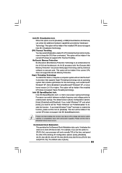
... use FAT32/16/12 file system. 13. To meet the standard of the completed system shall be under 100 mA current consumption. ASRock Instant Flash is higher than the recommended CPU bus frequencies may cause the instability of overclocking settings. EuP, stands for the operation procedures of Intelligent Energy Saver. With this...
... use FAT32/16/12 file system. 13. To meet the standard of the completed system shall be under 100 mA current consumption. ASRock Instant Flash is higher than the recommended CPU bus frequencies may cause the instability of overclocking settings. EuP, stands for the operation procedures of Intelligent Energy Saver. With this...
User Manual
Page 10
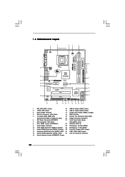
...1 USB4_5 USB6_7 1 SPEAKER1 1 SATAII_1 20 19 18 17 16 15 14 13 12 G41M-S3 SATAII_2 SATAII_4 24.4cm (9.6 in) 6 7 8 9 10 11 1 PS2_USB_PWR1 Jumper 15 USB 2.0 Header (USB6_7, Blue) 2 775-Pin CPU Socket 16 USB 2.0 Header (USB4_5, Blue) 3 North Bridge Controller 17 System Panel ...Header (PANEL1, Orange) 4 CPU Fan Connector (CPU_FAN1) 18 BIOS SPI Chip 5 2 x 240-pin DDR3 DIMM Slots 19 Chassis Fan Connector...
...1 USB4_5 USB6_7 1 SPEAKER1 1 SATAII_1 20 19 18 17 16 15 14 13 12 G41M-S3 SATAII_2 SATAII_4 24.4cm (9.6 in) 6 7 8 9 10 11 1 PS2_USB_PWR1 Jumper 15 USB 2.0 Header (USB6_7, Blue) 2 775-Pin CPU Socket 16 USB 2.0 Header (USB4_5, Blue) 3 North Bridge Controller 17 System Panel ...Header (PANEL1, Orange) 4 CPU Fan Connector (CPU_FAN1) 18 BIOS SPI Chip 5 2 x 240-pin DDR3 DIMM Slots 19 Chassis Fan Connector...

User Manual
Page 13
...position at approximately 135 degrees. Step 2. black line black line Step 2-2. Open the socket: CPU Marked Corner Step 1-1. Hold the CPU by depressing down and out on the socket. Orient the CPU with black lines. Pin1 orientation key notch orientation key notch Pin1 alignment key alignment key 775-... socket if above situation is any bent pin on the ShoockoetkMatrokedcCleoranerr retention tab. Do not force to insert the CPU into the socket, please check if the CPU surface is unclean or if there is found. Rotate the load lever to fully open position at approximately 100 ...
...position at approximately 135 degrees. Step 2. black line black line Step 2-2. Open the socket: CPU Marked Corner Step 1-1. Hold the CPU by depressing down and out on the socket. Orient the CPU with black lines. Pin1 orientation key notch orientation key notch Pin1 alignment key alignment key 775-... socket if above situation is any bent pin on the ShoockoetkMatrokedcCleoranerr retention tab. Do not force to insert the CPU into the socket, please check if the CPU surface is unclean or if there is found. Rotate the load lever to fully open position at approximately 100 ...

User Manual
Page 14
It is within the socket and properly mated to the orient keys. Step 4-2. Step 3. Verify that the CPU is recommended to use the cap tab to handle and avoid kicking off the PnP cap. 2. Remove PnP Cap (Pick and Place Cap): Use your ... the load lever. Step 4-3. For proper inserting, please ensure to match the two orientation key notches of the CPU with load plate tab under retention tab of load lever. 14 Carefully place the CPU into the socket by using a purely vertical motion. Rotate the load plate onto the IHS. Close the socket...
It is within the socket and properly mated to the orient keys. Step 4-2. Step 3. Verify that the CPU is recommended to use the cap tab to handle and avoid kicking off the PnP cap. 2. Remove PnP Cap (Pick and Place Cap): Use your ... the load lever. Step 4-3. For proper inserting, please ensure to match the two orientation key notches of the CPU with load plate tab under retention tab of load lever. 14 Carefully place the CPU into the socket by using a purely vertical motion. Rotate the load plate onto the IHS. Close the socket...

User Manual
Page 15
...Repeat with thumb to install and lock. Ensure fan cables are securely fastened and in good contact with 775-Pin socket that the CPU and the heatsink are oriented on fastener caps with remaining fasteners. Rotate the fastener clockwise, then press down the fasteners without rotating them... center of heatsink and cooling fan compliant with the motherboard throughholes. Step 2. If you need to spray thermal interface material between the CPU and the heatsink to improve heat dissipation. Connect fan header with fan operation or contact other . Secure excess cable with tie-wrap ...
...Repeat with thumb to install and lock. Ensure fan cables are securely fastened and in good contact with 775-Pin socket that the CPU and the heatsink are oriented on fastener caps with remaining fasteners. Rotate the fastener clockwise, then press down the fasteners without rotating them... center of heatsink and cooling fan compliant with the motherboard throughholes. Step 2. If you need to spray thermal interface material between the CPU and the heatsink to improve heat dissipation. Connect fan header with fan operation or contact other . Secure excess cable with tie-wrap ...
User Manual
Page 19
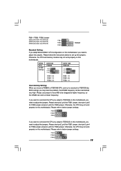
... properly on this motherboard. Please short pin2, pin3 for FSB1 jumper, short pin3, pin4 for FSB2 jumper and pin4, pin5 for FSB3 jumper. DRAM CPU Jumper Settings DDR3 533 FSB533 FSB1 FSB2 FSB3 DDR3 1333 FSB1333 FSB1 FSB2 FSB3 FSB1: 2-3 FSB2: 1-2 FSB3: 2-3 FSB1: 1-2 FSB2: 4-5 FSB3...pin4, pin5 for FSB3 jumper. Please refer to be overclocked very high. Otherwise, the CPU and memory module may face the problem, that DRAM frequency will be strapped at lower frequency. Otherwise, the CPU may not work properly on this motherboard. FSB1 / FSB2 / FSB3 Jumper (FSB1,...
... properly on this motherboard. Please short pin2, pin3 for FSB1 jumper, short pin3, pin4 for FSB2 jumper and pin4, pin5 for FSB3 jumper. DRAM CPU Jumper Settings DDR3 533 FSB533 FSB1 FSB2 FSB3 DDR3 1333 FSB1333 FSB1 FSB2 FSB3 FSB1: 2-3 FSB2: 1-2 FSB3: 2-3 FSB1: 1-2 FSB2: 4-5 FSB3...pin4, pin5 for FSB3 jumper. Please refer to be overclocked very high. Otherwise, the CPU and memory module may face the problem, that DRAM frequency will be strapped at lower frequency. Otherwise, the CPU may not work properly on this motherboard. FSB1 / FSB2 / FSB3 Jumper (FSB1,...

User Manual
Page 22
...Header (4-pin SPEAKER 1) (see p.10 No. 14) Chassis Fan Connector (3-pin CHA_FAN1) (see p.10 No. 4) 4 3 2 1 GND +12V CPU_FAN_SPEED FAN_SPEED_CONTROL Please connect a CPU fan cable to this motherboard, please connect it to hear your voice through front mic, please deselect "Mute" icon in the Realtek Control panel. To..." portion. "Disable front panel jack detection", and save the change by clicking "OK". If you plan to connect the 3-Pin CPU fan to the CPU fan connector on this connector and match the black wire to make the Front Mic as default record device. Pin 1-3 Connected 3-Pin...
...Header (4-pin SPEAKER 1) (see p.10 No. 14) Chassis Fan Connector (3-pin CHA_FAN1) (see p.10 No. 4) 4 3 2 1 GND +12V CPU_FAN_SPEED FAN_SPEED_CONTROL Please connect a CPU fan cable to this motherboard, please connect it to hear your voice through front mic, please deselect "Mute" icon in the Realtek Control panel. To..." portion. "Disable front panel jack detection", and save the change by clicking "OK". If you plan to connect the 3-Pin CPU fan to the CPU fan connector on this connector and match the black wire to make the Front Mic as default record device. Pin 1-3 Connected 3-Pin...
User Manual
Page 25
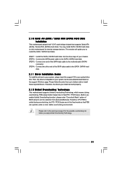
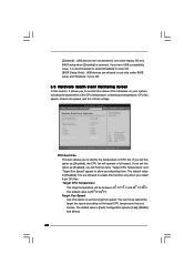
... / SATAII hard disk. 2.11 Driver Installation Guide To install the drivers to your system, please insert the support CD to fixed PCI / PCIE buses. Therefore, CPU FSB is untied during overclocking, FSB enjoys better margin due to your chassis. You may install SATA / SATAII hard disks on this motherboard for the...
... / SATAII hard disk. 2.11 Driver Installation Guide To install the drivers to your system, please insert the support CD to fixed PCI / PCIE buses. Therefore, CPU FSB is untied during overclocking, FSB enjoys better margin due to your chassis. You may install SATA / SATAII hard disks on this motherboard for the...
User Manual
Page 27
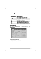
... Tweaker Advanced H/W Monitor Boot Security Exit System Overview System Time System Date [14:00:09] [Fri 10/16/2009] BIOS Version : G41M-S3 P1.00 Processor Type : Intel (R) Core (TM) 2 Duo CPU E6850 @ 3.00GHz (64bit) Processor Speed : 3148MHz Microcode Update : 6FB/B6 Cache Size : 1024KB Total Memory DDR3_1 DDR3_2 : 1024MB with 128MB shared...
... Tweaker Advanced H/W Monitor Boot Security Exit System Overview System Time System Date [14:00:09] [Fri 10/16/2009] BIOS Version : G41M-S3 P1.00 Processor Type : Intel (R) Core (TM) 2 Duo CPU E6850 @ 3.00GHz (64bit) Processor Speed : 3148MHz Microcode Update : 6FB/B6 Cache Size : 1024KB Total Memory DDR3_1 DDR3_2 : 1024MB with 128MB shared...
User Manual
Page 28
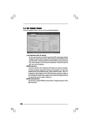
... note that overclocing may cause damage to your own risk and expense. Select Screen Select Item Enter Go to page 8 for the CPU FSB frequency and its corresponding memory support frequency. Please refer to Sub Screen F1 General Help F9 Load Defaults F10 Save and Exit ....54 (C) Copyright 1985-2005, American Megatrends, Inc. BIOS SETUP UTILITY Main OC Tweaker Advanced H/W Monitor Boot Security Exit OC Tweaker Settings Load Optimized CPU OC Setting [Press Enter] DRAM Frequency DRAM Command Rate DRAM Timing Configuration [Auto] [Auto] Ratio Status Unlocked (Min:06, Max:17) Ratio...
... note that overclocing may cause damage to your own risk and expense. Select Screen Select Item Enter Go to page 8 for the CPU FSB frequency and its corresponding memory support frequency. Please refer to Sub Screen F1 General Help F9 Load Defaults F10 Save and Exit ....54 (C) Copyright 1985-2005, American Megatrends, Inc. BIOS SETUP UTILITY Main OC Tweaker Advanced H/W Monitor Boot Security Exit OC Tweaker Settings Load Optimized CPU OC Setting [Press Enter] DRAM Frequency DRAM Command Rate DRAM Timing Configuration [Auto] [Auto] Ratio Status Unlocked (Min:06, Max:17) Ratio...
User Manual
Page 30
...Use this feature is "Locked" or "Unlocked". The default value of this option to select Overclock Mode. The default value of this to adjust CPU frequency. in advance. The default value is [Auto]. Please note that enabling this feature is [Auto]. Overclock Mode Use this feature is [Auto... is Intel's new power saving technology. The default value of this to system stability or compatibility issue with some power supplies. If the CPU you adopt supports EIST (Intel (R) SpeedStep(tm) tech.), and you install Windows® VistaTM and want to enable this function, please set...
...Use this feature is "Locked" or "Unlocked". The default value of this option to select Overclock Mode. The default value of this to adjust CPU frequency. in advance. The default value is [Auto]. Please note that enabling this feature is [Auto]. Overclock Mode Use this feature is [Auto... is Intel's new power saving technology. The default value of this to system stability or compatibility issue with some power supplies. If the CPU you adopt supports EIST (Intel (R) SpeedStep(tm) tech.), and you install Windows® VistaTM and want to enable this function, please set...
User Manual
Page 31
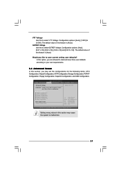
...Save and Exit ESC Exit v02.54 (C) Copyright 1985-2005, American Megatrends, Inc. Options for the following items: CPU Configuration, Chipset Configuration, ACPI Configuration, Storage Configuration, PCIPnP Configuration, Floppy Configuration, SuperIO Configuration, and USB Configuration. Configuration...in below sections may set the configurations for CPU CPU Configuration Chipset Configuration ACPI Configuration Storage Configuration PCIPnP Configuration Floppy Configuration SuperIO Configuration USB Configuration BIOS Update Utility ASRock Instant Flash Select Screen Select Item Enter Go...
...Save and Exit ESC Exit v02.54 (C) Copyright 1985-2005, American Megatrends, Inc. Options for the following items: CPU Configuration, Chipset Configuration, ACPI Configuration, Storage Configuration, PCIPnP Configuration, Floppy Configuration, SuperIO Configuration, and USB Configuration. Configuration...in below sections may set the configurations for CPU CPU Configuration Chipset Configuration ACPI Configuration Storage Configuration PCIPnP Configuration Floppy Configuration SuperIO Configuration USB Configuration BIOS Update Utility ASRock Instant Flash Select Screen Select Item Enter Go...

User Manual
Page 32
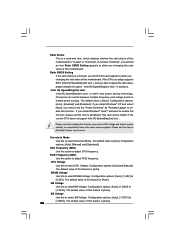
... through the native processor instructions HLT and MWAIT and requires no hardware support from the chipset. 3.4.1 CPU Configuration BIOS SETUP UTILITY Advanced CPU Configuration Overclock Mode CPU Frequency (MHz) PCIE Frequency (MHz) Boot Failure Guard Spread Spectrum [Auto] [200] [100]... motherboard. Cnfiguration options: [Auto], [Manual] and [Optimized]. Boot Failure Guard Enable or disable the feature of the system caches. 32 CPU Thermal Throttling No-Execute Memory Protection Intel (R) SpeedStep (tm) tech. On-Demand Clock Mudulation [Disabled] [Enabled] [Enabled] [Disabled] ...
... through the native processor instructions HLT and MWAIT and requires no hardware support from the chipset. 3.4.1 CPU Configuration BIOS SETUP UTILITY Advanced CPU Configuration Overclock Mode CPU Frequency (MHz) PCIE Frequency (MHz) Boot Failure Guard Spread Spectrum [Auto] [200] [100]... motherboard. Cnfiguration options: [Auto], [Manual] and [Optimized]. Boot Failure Guard Enable or disable the feature of the system caches. 32 CPU Thermal Throttling No-Execute Memory Protection Intel (R) SpeedStep (tm) tech. On-Demand Clock Mudulation [Disabled] [Enabled] [Enabled] [Disabled] ...
User Manual
Page 33
...: [Auto], [Enabled] and [Disabled]. It indicates the clock on to enable power savings. This option will be hidden if the current CPU does not support No-Excute Memory Protection. No-Excute Memory Protection No-Execution (NX) Memory Protection Technology is an enhancement to execute code....Hyper Threading Technology To enable this feature, it requires a computer system with some power supplies. This item will be hidden if the installed CPU does not support Intel (R) Virtualization Technology. The default value is set this item to [Disable] if above issue occurs. Intel (R) ...
...: [Auto], [Enabled] and [Disabled]. It indicates the clock on to enable power savings. This option will be hidden if the current CPU does not support No-Excute Memory Protection. No-Excute Memory Protection No-Execution (NX) Memory Protection Technology is an enhancement to execute code....Hyper Threading Technology To enable this feature, it requires a computer system with some power supplies. This item will be hidden if the installed CPU does not support Intel (R) Virtualization Technology. The default value is set this item to [Disable] if above issue occurs. Intel (R) ...
User Manual
Page 46
...Screen Select Item General Help Load Defaults Save and Exit Exit v02.54 (C) Copyright 1985-2003, American Megatrends, Inc. If you install 4-pin CPU fan. The default value is [50 C/122 F]. The default value is [Disabled]. USB devices are allowed to set this function only when ...In this section, it is recommended to select [Disabled] to monitor the status of the hardware on your system, including the parameters of CPU fan. CPU Quiet Fan This item allows you adjusting them. [Disabled] - BIOS SETUP UTILITY Main OC Tweaker Advanced H/W Monitor Boot Security Exit Hardware ...
...Screen Select Item General Help Load Defaults Save and Exit Exit v02.54 (C) Copyright 1985-2003, American Megatrends, Inc. If you install 4-pin CPU fan. The default value is [50 C/122 F]. The default value is [Disabled]. USB devices are allowed to set this function only when ...In this section, it is recommended to select [Disabled] to monitor the status of the hardware on your system, including the parameters of CPU fan. CPU Quiet Fan This item allows you adjusting them. [Disabled] - BIOS SETUP UTILITY Main OC Tweaker Advanced H/W Monitor Boot Security Exit Hardware ...


