
User Manual
Page 6
... - 1 x PS/2 Keyboard Port - 1 x Serial Port: COM1 - 1 x VGA Port - 4 x Ready-to 2048x1536 @ 60Hz - 5.1 CH Windows® VistaTM Premium Level HD Audio (Realtek ALC662 Audio Codec) - LGA 775 for Intel® CoreTM 2 Extreme / CoreTM 2 Quad / CoreTM 2 Duo / Pentium® Dual Core / Celeron® Dual Core / Celeron®, supporting Penryn Quad Core Yorkfield and...
... - 1 x PS/2 Keyboard Port - 1 x Serial Port: COM1 - 1 x VGA Port - 4 x Ready-to 2048x1536 @ 60Hz - 5.1 CH Windows® VistaTM Premium Level HD Audio (Realtek ALC662 Audio Codec) - LGA 775 for Intel® CoreTM 2 Extreme / CoreTM 2 Quad / CoreTM 2 Duo / Pentium® Dual Core / Celeron® Dual Core / Celeron®, supporting Penryn Quad Core Yorkfield and...
User Manual
Page 10
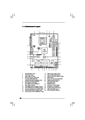
... PLED PWRBTN 1 1 HDLED RESET PANEL 1 USB4_5 USB6_7 1 SPEAKER1 1 SATAII_1 20 19 18 17 16 15 14 13 12 G41M-S3 SATAII_2 SATAII_4 24.4cm (9.6 in) 6 7 8 9 10 11 1 PS2_USB_PWR1 Jumper 15 USB 2.0 Header (USB6_7, Blue) 2 775-Pin CPU Socket 16 USB 2.0 Header (USB4_5, Blue) 3 North Bridge Controller 17 System Panel Header (PANEL1, Orange) 4 CPU...
... PLED PWRBTN 1 1 HDLED RESET PANEL 1 USB4_5 USB6_7 1 SPEAKER1 1 SATAII_1 20 19 18 17 16 15 14 13 12 G41M-S3 SATAII_2 SATAII_4 24.4cm (9.6 in) 6 7 8 9 10 11 1 PS2_USB_PWR1 Jumper 15 USB 2.0 Header (USB6_7, Blue) 2 775-Pin CPU Socket 16 USB 2.0 Header (USB4_5, Blue) 3 North Bridge Controller 17 System Panel Header (PANEL1, Orange) 4 CPU...

User Manual
Page 13
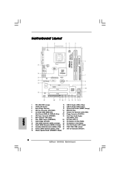
... if the CPU surface is unclean or if there is found. Insert the 775-LAND CPU: Step 2-1. 2.3 CPU Installation For the installation of Intel 775-LAND CPU, please follow the steps below. 775-Pin Socket Overview Before you insert the 775-LAND CPU into the socket if above situation is any bent pin on... socket: CPU Marked Corner Step 1-1. Locate Pin1 and the two orientation key notches. Pin1 orientation key notch orientation key notch Pin1 alignment key alignment key 775-LAND CPU 775-Pin Socket 13
... if the CPU surface is unclean or if there is found. Insert the 775-LAND CPU: Step 2-1. 2.3 CPU Installation For the installation of Intel 775-LAND CPU, please follow the steps below. 775-Pin Socket Overview Before you insert the 775-LAND CPU into the socket if above situation is any bent pin on... socket: CPU Marked Corner Step 1-1. Locate Pin1 and the two orientation key notches. Pin1 orientation key notch orientation key notch Pin1 alignment key alignment key 775-LAND CPU 775-Pin Socket 13

User Manual
Page 15
... operation or contact other . Ensure fan cables are securely fastened and in good contact with Intel 775-LAND CPU to ensure cable does not interfere with 775-Pin socket that supports Intel 775-LAND CPU. If you need to spray thermal interface material between the CPU and the heatsink to...(CPU_FAN1, see page 10, No. 4). 2.4 Installation of CPU Fan and Heatsink This motherboard is an example to illustrate the installation of the heatsink for 775-LAND CPU. Then connect the CPU fan to the CPU_FAN connector (CPU_FAN1, see page 10, No. 4). Step 5. Ensure that the CPU and the ...
... operation or contact other . Ensure fan cables are securely fastened and in good contact with Intel 775-LAND CPU to ensure cable does not interfere with 775-Pin socket that supports Intel 775-LAND CPU. If you need to spray thermal interface material between the CPU and the heatsink to...(CPU_FAN1, see page 10, No. 4). 2.4 Installation of CPU Fan and Heatsink This motherboard is an example to illustrate the installation of the heatsink for 775-LAND CPU. Then connect the CPU fan to the CPU_FAN connector (CPU_FAN1, see page 10, No. 4). Step 5. Ensure that the CPU and the ...
Quick Installation Guide
Page 2
... Slot (PCIE2) 10 Third SATAII Connector (SATAII_3; Red) 27 ATX 12V Connector (ATX12V1) 14 Chassis Speaker Header (SPEAKER 1, Purple) 2 ASRock G41M-S3 Motherboard Motherboard Layout English 1 PS2_USB_PWR1 Jumper 15 USB 2.0 Header (USB6_7, Blue) 2 775-Pin CPU Socket 16 USB 2.0 Header (USB4_5, Blue) 3 North Bridge Controller 17 System Panel Header (PANEL1, Orange) 4 CPU Fan Connector...
... Slot (PCIE2) 10 Third SATAII Connector (SATAII_3; Red) 27 ATX 12V Connector (ATX12V1) 14 Chassis Speaker Header (SPEAKER 1, Purple) 2 ASRock G41M-S3 Motherboard Motherboard Layout English 1 PS2_USB_PWR1 Jumper 15 USB 2.0 Header (USB6_7, Blue) 2 775-Pin CPU Socket 16 USB 2.0 Header (USB4_5, Blue) 3 North Bridge Controller 17 System Panel Header (PANEL1, Orange) 4 CPU Fan Connector...
Quick Installation Guide
Page 5
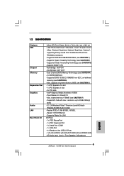
...Windows® VistaTM Premium Level HD Audio (Realtek ALC662 Audio Codec) - Micro ATX Form Factor: 9.6-in x 7.6-in / Front Speaker / Microphone English 5 ASRock G41M-S3 Motherboard Supports EM64T CPU - Dual Channel DDR3 Memory Technology (see CAUTION 5) - Realtek PCIE x1 LAN 8103EL / 8102EL - Northbridge: Intel® G41 - Intel...Sub with LED (ACT/LINK LED and SPEED LED) - resolution up to -Use USB 2.0 Ports - 1 x RJ-45 LAN Port with max. LGA 775 for Intel® CoreTM 2 Extreme / CoreTM 2 Quad / CoreTM 2 Duo / Pentium® Dual Core / Celeron® Dual Core / Celeron®,...
...Windows® VistaTM Premium Level HD Audio (Realtek ALC662 Audio Codec) - Micro ATX Form Factor: 9.6-in x 7.6-in / Front Speaker / Microphone English 5 ASRock G41M-S3 Motherboard Supports EM64T CPU - Dual Channel DDR3 Memory Technology (see CAUTION 5) - Realtek PCIE x1 LAN 8103EL / 8102EL - Northbridge: Intel® G41 - Intel...Sub with LED (ACT/LINK LED and SPEED LED) - resolution up to -Use USB 2.0 Ports - 1 x RJ-45 LAN Port with max. LGA 775 for Intel® CoreTM 2 Extreme / CoreTM 2 Quad / CoreTM 2 Duo / Pentium® Dual Core / Celeron® Dual Core / Celeron®,...
Quick Installation Guide
Page 9
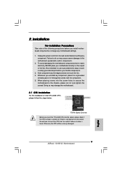
... power cord from the wall socket before you insert the 775-LAND CPU into the socket if above situation is any motherboard settings. 1. Doing so may cause severe damage to do not touch the ICs. 4. Otherwise, the CPU will be seriously damaged. 9 ASRock G41M-S3 Motherboard English Hold components by the edges and do...
... power cord from the wall socket before you insert the 775-LAND CPU into the socket if above situation is any motherboard settings. 1. Doing so may cause severe damage to do not touch the ICs. 4. Otherwise, the CPU will be seriously damaged. 9 ASRock G41M-S3 Motherboard English Hold components by the edges and do...
Quick Installation Guide
Page 10
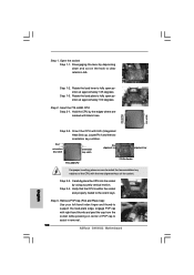
... alignment key alignment key 775-LAND CPU 775-Pin Socket For proper inserting, please ensure to the orient keys. Step 3. Orient the CPU with right hand thumb and peel the cap from the socket while pressing on the hook to assist in removal. 10 ASRock G41M-S3 Motherboard Step 2-4. Step ...1. Remove PnP Cap (Pick and Place Cap): Use your left hand index finger and thumb to support the load plate edge, engage PnP cap with IHS (Integrated Heat Sink) up. Insert the 775-LAND CPU: Step 2-1. Step 1-2....
... alignment key alignment key 775-LAND CPU 775-Pin Socket For proper inserting, please ensure to the orient keys. Step 3. Orient the CPU with right hand thumb and peel the cap from the socket while pressing on the hook to assist in removal. 10 ASRock G41M-S3 Motherboard Step 2-4. Step ...1. Remove PnP Cap (Pick and Place Cap): Use your left hand index finger and thumb to support the load plate edge, engage PnP cap with IHS (Integrated Heat Sink) up. Insert the 775-LAND CPU: Step 2-1. Step 1-2....
Quick Installation Guide
Page 11
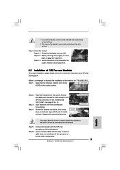
...onto the socket. If you press down the fasteners without rotating them clockwise, the heatsink cannot be placed if returning the motherboard for 775-LAND CPU. Connect fan header with thumb to illustrate the installation of the heatsink for after service. Rotate the load plate onto the...PnP cap. 2. While pressing down on the socket surface. Step 3. Step 4. Align fasteners with fan operation or contact other components. 11 ASRock G41M-S3 Motherboard English Step 5. Below is recommended to use the cap tab to the instruction manuals of IHS on fastener caps with the CPU fan ...
...onto the socket. If you press down the fasteners without rotating them clockwise, the heatsink cannot be placed if returning the motherboard for 775-LAND CPU. Connect fan header with thumb to illustrate the installation of the heatsink for after service. Rotate the load plate onto the...PnP cap. 2. While pressing down on the socket surface. Step 3. Step 4. Align fasteners with fan operation or contact other components. 11 ASRock G41M-S3 Motherboard English Step 5. Below is recommended to use the cap tab to the instruction manuals of IHS on fastener caps with the CPU fan ...