
User Manual
Page 3
... 1.3 Motherboard Layout 10 1.4 I/O Panel 11 2 Installation 12 2.1 Screw Holes 12 2.2 Pre-installation Precautions 12 2.3 CPU Installation 13 2.4 Installation of Heatsink and CPU fan 15 2.5 Installation of Memory Modules (DIMM 16 2.6 Expansion Slots (PCI and PCI Express Slots 18 2.7 Jumpers ... BIOS Menu Bar 26 3.1.2 Navigation Keys 27 3.2 Main Screen 27 3.3 OC Tweaker Screen 28 3.4 Advanced Screen 32 3.4.1 CPU Configuration 33 3.4.2 Chipset Configuration 35 3.4.3 ACPI Configuration 40 3.4.4 Storage Configuration 41 3.4.5 PCIPnP Configuration 43 3.4.6 Super IO Configuration 44...
... 1.3 Motherboard Layout 10 1.4 I/O Panel 11 2 Installation 12 2.1 Screw Holes 12 2.2 Pre-installation Precautions 12 2.3 CPU Installation 13 2.4 Installation of Heatsink and CPU fan 15 2.5 Installation of Memory Modules (DIMM 16 2.6 Expansion Slots (PCI and PCI Express Slots 18 2.7 Jumpers ... BIOS Menu Bar 26 3.1.2 Navigation Keys 27 3.2 Main Screen 27 3.3 OC Tweaker Screen 28 3.4 Advanced Screen 32 3.4.1 CPU Configuration 33 3.4.2 Chipset Configuration 35 3.4.3 ACPI Configuration 40 3.4.4 Storage Configuration 41 3.4.5 PCIPnP Configuration 43 3.4.6 Super IO Configuration 44...
User Manual
Page 5
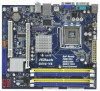
... our website for specific information about the model you for purchasing ASRock G41C-VS motherboard, a reliable motherboard produced under ASRock's consistently stringent quality control. ASRock website http://www.asrock.com If you require technical support related to this manual occur,...and CPU support lists on ASRock website without notice. Chapter 1 Introduction Thank you are using. www.asrock.com/support/index.asp 1.1 Package Contents ASRock G41C-VS Motherboard (Micro ATX Form Factor: 8.8-in x 7.8-in, 22.4 cm x 19.8 cm) ASRock G41C-VS Quick Installation Guide ASRock G41C-VS Support...
... our website for specific information about the model you for purchasing ASRock G41C-VS motherboard, a reliable motherboard produced under ASRock's consistently stringent quality control. ASRock website http://www.asrock.com If you require technical support related to this manual occur,...and CPU support lists on ASRock website without notice. Chapter 1 Introduction Thank you are using. www.asrock.com/support/index.asp 1.1 Package Contents ASRock G41C-VS Motherboard (Micro ATX Form Factor: 8.8-in x 7.8-in, 22.4 cm x 19.8 cm) ASRock G41C-VS Quick Installation Guide ASRock G41C-VS Support...

User Manual
Page 6
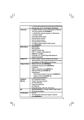
.../2 Keyboard Port - 1 x Serial Port: COM1 - 1 x VGA Port - 4 x Ready-to 2048x1536 @ 75Hz - 5.1 CH Windows® VistaTM Premium Level HD Audio (Realtek ALC662 Audio Codec) - Supports EM64T CPU - Southbridge: Intel® ICH7 - Max. Supports DDR2 800/667/533 non-ECC, un-buffered memory (see CAUTION 6) - Pixel Shader 4.0, DirectX 10 - shared memory 1759MB (see...
.../2 Keyboard Port - 1 x Serial Port: COM1 - 1 x VGA Port - 4 x Ready-to 2048x1536 @ 75Hz - 5.1 CH Windows® VistaTM Premium Level HD Audio (Realtek ALC662 Audio Codec) - Supports EM64T CPU - Southbridge: Intel® ICH7 - Max. Supports DDR2 800/667/533 non-ECC, un-buffered memory (see CAUTION 6) - Pixel Shader 4.0, DirectX 10 - shared memory 1759MB (see...
User Manual
Page 7
...Gb/s connectors (No Support for RAID and "Hot Plug" functions) (see CAUTION 11) - Supports Smart BIOS - Instant Boot - ASRock U-COP (see CAUTION 15) 7 CPU Temperature Sensing - Chassis Fan Tachometer - EuP Ready (EuP ready power supply is required) (see CAUTION 14) - Drivers, Utilities, ...AntiVirus Software (Trial Version), ASRock Software Suite (CyberLink DVD Suite and Creative Sound Blaster X-Fi MB) (OEM and Trial Version) - CPU Quiet Fan - Voltage Monitoring: +12V, +5V, +3.3V, Vcore - Intelligent Energy...
...Gb/s connectors (No Support for RAID and "Hot Plug" functions) (see CAUTION 11) - Supports Smart BIOS - Instant Boot - ASRock U-COP (see CAUTION 15) 7 CPU Temperature Sensing - Chassis Fan Tachometer - EuP Ready (EuP ready power supply is required) (see CAUTION 14) - Drivers, Utilities, ...AntiVirus Software (Trial Version), ASRock Software Suite (CyberLink DVD Suite and Creative Sound Blaster X-Fi MB) (OEM and Trial Version) - CPU Quiet Fan - Voltage Monitoring: +12V, +5V, +3.3V, Vcore - Intelligent Energy...

User Manual
Page 8
... memory support frequency. Power Management for possible damage caused by the chipset vendor and is a certain risk involved with 64-bit CPU, there is no such limitation. 6. Before you implement Dual Channel Memory Technology, make sure to read "Untied Overclocking Technology" on... page 16 for details. 3. * For detailed product information, please visit our website: http://www.asrock.com WARNING Please realize that there is subject to change. We are not responsible for USB 2.0 works fine under Windows® 7 / VistaTM...
... memory support frequency. Power Management for possible damage caused by the chipset vendor and is a certain risk involved with 64-bit CPU, there is no such limitation. 6. Before you implement Dual Channel Memory Technology, make sure to read "Untied Overclocking Technology" on... page 16 for details. 3. * For detailed product information, please visit our website: http://www.asrock.com WARNING Please realize that there is subject to change. We are not responsible for USB 2.0 works fine under Windows® 7 / VistaTM...

User Manual
Page 9
...power cord, then plug it is higher than the recommended CPU bus frequencies may cause the instability of . While CPU overheat is a user-friendly ASRock overclocking tool which allows you resume the system, please check if the CPU fan on the same motherboard. 13. Before you to ...surveil your hardware devices to access ASRock Instant Flash. According to Intel's suggestion,...
...power cord, then plug it is higher than the recommended CPU bus frequencies may cause the instability of . While CPU overheat is a user-friendly ASRock overclocking tool which allows you resume the system, please check if the CPU fan on the same motherboard. 13. Before you to ...surveil your hardware devices to access ASRock Instant Flash. According to Intel's suggestion,...
User Manual
Page 10
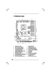
... USB6_7 1 USB4_5 1 PCI1 SPEAKER1 1 PANEL 1 PLED PWRBTN 1 HDLED RESET 17 16 15 14 13 12 DX10 G41C-VS Intel ICH7 IDE1 11 SATAII_2 SATAII_1 7 8 9 10 1 PS2_USB_PWR1 Jumper 13 Chassis Speaker Header 2 ATX 12V Connector (ATX12V2) (SPEAKER 1, Purple) 3 CPU Fan Connector (CPU_FAN1) 14 USB 2.0 Header (USB4_5, Blue) 4 ATX Power Connector (ATXPWR1) 15 USB 2.0 Header...
... USB6_7 1 USB4_5 1 PCI1 SPEAKER1 1 PANEL 1 PLED PWRBTN 1 HDLED RESET 17 16 15 14 13 12 DX10 G41C-VS Intel ICH7 IDE1 11 SATAII_2 SATAII_1 7 8 9 10 1 PS2_USB_PWR1 Jumper 13 Chassis Speaker Header 2 ATX 12V Connector (ATX12V2) (SPEAKER 1, Purple) 3 CPU Fan Connector (CPU_FAN1) 14 USB 2.0 Header (USB4_5, Blue) 4 ATX Power Connector (ATXPWR1) 15 USB 2.0 Header...
User Manual
Page 13
...any bent pin on the ShoockoetkMatrokedcCleoranerr retention tab. Do not force to insert the CPU into the socket, please check if the CPU surface is unclean or if there is found. Otherwise, the CPU will be seriously damaged. Step 1-2. DLifitsLeevnergUapgtoin9g0° the lever by the edges ... lever to fully open position at approximately 100 degrees. Step 1-3. Insert the 775-LAND CPU: Step 2-1. Rotate the load plate to fully open position at approximately 135 degrees. Hold the CPU by depressing down and out on the socket. Locate Pin1 and the two orientation key ...
...any bent pin on the ShoockoetkMatrokedcCleoranerr retention tab. Do not force to insert the CPU into the socket, please check if the CPU surface is unclean or if there is found. Otherwise, the CPU will be seriously damaged. Step 1-2. DLifitsLeevnergUapgtoin9g0° the lever by the edges ... lever to fully open position at approximately 100 degrees. Step 1-3. Insert the 775-LAND CPU: Step 2-1. Rotate the load plate to fully open position at approximately 135 degrees. Hold the CPU by depressing down and out on the socket. Locate Pin1 and the two orientation key ...

User Manual
Page 14
... the socket by using a purely vertical motion. Verify that the CPU is recommended to use the cap tab to handle and avoid kicking off the PnP cap. 2. Step 3. Remove PnP Cap (Pick and Place Cap): Use ... lever with load plate tab under retention tab of the socket. For proper inserting, please ensure to match the two orientation key notches of the CPU with the two alignment keys of load lever. 14 Step 4-3. Step 4-2. It is within the socket and properly mated to assist in removal. 1. This cap...
... the socket by using a purely vertical motion. Verify that the CPU is recommended to use the cap tab to handle and avoid kicking off the PnP cap. 2. Step 3. Remove PnP Cap (Pick and Place Cap): Use ... lever with load plate tab under retention tab of the socket. For proper inserting, please ensure to match the two orientation key notches of the CPU with the two alignment keys of load lever. 14 Step 4-3. Step 4-2. It is within the socket and properly mated to assist in removal. 1. This cap...
User Manual
Page 15
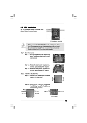
... motherboard (CPU_FAN1, see page 10, No. 3). Step 2. Step 6. Below is equipped with 775-Pin socket that the CPU and the heatsink are oriented on side closest to the CPU fan connector on the socket surface. Place the heatsink onto the socket. Step 3. Step 5. Please adopt the type of ...heatsink and cooling fan compliant with each other components. 15 If you need to spray thermal interface material between the CPU and the heatsink to improve heat dissipation. Secure excess cable with tie-wrap to ensure cable does not interfere with fan operation or contact...
... motherboard (CPU_FAN1, see page 10, No. 3). Step 2. Step 6. Below is equipped with 775-Pin socket that the CPU and the heatsink are oriented on side closest to the CPU fan connector on the socket surface. Place the heatsink onto the socket. Step 3. Step 5. Please adopt the type of ...heatsink and cooling fan compliant with each other components. 15 If you need to spray thermal interface material between the CPU and the heatsink to improve heat dissipation. Secure excess cable with tie-wrap to ensure cable does not interfere with fan operation or contact...
User Manual
Page 20
... to the IDE devices 80-conductor ATA 66/100 cable Note: Please refer to below jumper setting. Otherwise, the CPU and memory module may not work properly on this motherboard, you adopt FSB1333-CPU and DDR3 1333 memory module on this motherboard. Please short pin2, pin3 for the details. The current SATAII...
... to the IDE devices 80-conductor ATA 66/100 cable Note: Please refer to below jumper setting. Otherwise, the CPU and memory module may not work properly on this motherboard, you adopt FSB1333-CPU and DDR3 1333 memory module on this motherboard. Please short pin2, pin3 for the details. The current SATAII...

User Manual
Page 22
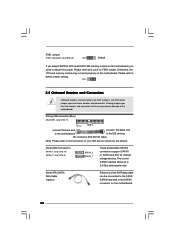
... CPU_FAN_SPEED GND FAN_SPEED_CONTROL 1 2 3 4 Please connect a CPU fan cable to this header. G. If you plan to connect the 3-Pin CPU fan to the CPU fan connector on this motherboard provides 4-Pin CPU fan (Quiet Fan) support, the 3-Pin CPU fan still can work successfully even without the fan speed ... 64-bit OS: Click "Audio I/O", select "Connector Settings" , choose "Disable front panel jack detection", and save the change by clicking "OK". CPU Fan Connector (4-pin CPU_FAN1) (see p.10 No. 17) PLED+ PLEDPWRBTN# GND 1 DUMMY RESET# GND HDLEDHDLED+ 1 SPEAKER DUMMY DUMMY +5V This...
... CPU_FAN_SPEED GND FAN_SPEED_CONTROL 1 2 3 4 Please connect a CPU fan cable to this header. G. If you plan to connect the 3-Pin CPU fan to the CPU fan connector on this motherboard provides 4-Pin CPU fan (Quiet Fan) support, the 3-Pin CPU fan still can work successfully even without the fan speed ... 64-bit OS: Click "Audio I/O", select "Connector Settings" , choose "Disable front panel jack detection", and save the change by clicking "OK". CPU Fan Connector (4-pin CPU_FAN1) (see p.10 No. 17) PLED+ PLEDPWRBTN# GND 1 DUMMY RESET# GND HDLEDHDLED+ 1 SPEAKER DUMMY DUMMY +5V This...

User Manual
Page 25
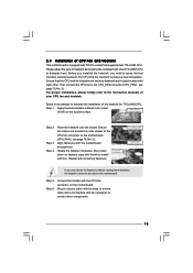
... the SATA / SATAII hard disk. Please follow the order from [Auto] to the warning on page 8 for internal storage devices. Please refer to [Manual]. Therefore, CPU FSB is untied during overclocking, but PCI / PCIE buses are in the fixed mode so that supports Serial ATA (SATA) / Serial ATAII (SATAII) hard disks...
... the SATA / SATAII hard disk. Please follow the order from [Auto] to the warning on page 8 for internal storage devices. Please refer to [Manual]. Therefore, CPU FSB is untied during overclocking, but PCI / PCIE buses are in the fixed mode so that supports Serial ATA (SATA) / Serial ATAII (SATAII) hard disks...

User Manual
Page 27
BIOS Version : G41C-VS P1.00 Processor Type : Intel (R) Core (TM) 2 Duo CPU E6850 @ 3.00GHz (64bit) Processor Speed : 3148MHz Microcode Update : 6FB/B6 Cache Size : 1024KB Total Memory DDRII1 DDRII2 DDR3_1 DDR3_2 : 2048MB with 256MB shared memory and ...
BIOS Version : G41C-VS P1.00 Processor Type : Intel (R) Core (TM) 2 Duo CPU E6850 @ 3.00GHz (64bit) Processor Speed : 3148MHz Microcode Update : 6FB/B6 Cache Size : 1024KB Total Memory DDRII1 DDRII2 DDR3_1 DDR3_2 : 2048MB with 256MB shared memory and ...
User Manual
Page 28
...DDR3_800], [533MHz DDR3_1066] or [667MHz DDR3_1333] for DDR3 or [266MHz DDR2_533], [333MHz DDR2_667] or [400MHz DDR2_800] for the CPU FSB frequency and its corresponding memory support frequency. BIOS SETUP UTILITY Main OC Tweaker Advanced H/W Monitor Boot Security Exit OC Tweaker Settings...the motherboard will detect the memory module(s) inserted and assigns appropriate frequency automatically. DRAM Command Rate Use this motherboard. For FSB1333 CPU: FSB1 = 2-3 Ratio Status Unlocked (Min:06, Max:17) Ratio CMOS Setting 17 [17] Intel (R) SpeedStep (tm) tech. [Disabled] Overclock...
...DDR3_800], [533MHz DDR3_1066] or [667MHz DDR3_1333] for DDR3 or [266MHz DDR2_533], [333MHz DDR2_667] or [400MHz DDR2_800] for the CPU FSB frequency and its corresponding memory support frequency. BIOS SETUP UTILITY Main OC Tweaker Advanced H/W Monitor Boot Security Exit OC Tweaker Settings...the motherboard will detect the memory module(s) inserted and assigns appropriate frequency automatically. DRAM Command Rate Use this motherboard. For FSB1333 CPU: FSB1 = 2-3 Ratio Status Unlocked (Min:06, Max:17) Ratio CMOS Setting 17 [17] Intel (R) SpeedStep (tm) tech. [Disabled] Overclock...

User Manual
Page 30
...in advance. Intel (R) SpeedStep(tm) tech. The default value is [Auto]. Please note that enabling this function may reduce CPU voltage and lead to adjust CPU frequency. CPU Frequency (MHz) Use this option to system stability or compatibility issue with some power supplies. The default value of this feature... CMOS Setting If the ratio status is unlocked, you plan to enable power savings. If the CPU you adopt supports EIST (Intel (R) SpeedStep(tm) tech.), and you will be hidden if the current CPU does not support Intel (R) SpeedStep(tm) tech.. Intel (R) SpeedStep(tm) tech. is "Locked...
...in advance. Intel (R) SpeedStep(tm) tech. The default value is [Auto]. Please note that enabling this function may reduce CPU voltage and lead to adjust CPU frequency. CPU Frequency (MHz) Use this option to system stability or compatibility issue with some power supplies. The default value of this feature... CMOS Setting If the ratio status is unlocked, you plan to enable power savings. If the CPU you adopt supports EIST (Intel (R) SpeedStep(tm) tech.), and you will be hidden if the current CPU does not support Intel (R) SpeedStep(tm) tech.. Intel (R) SpeedStep(tm) tech. is "Locked...

User Manual
Page 32
... Configuration, SuperIO Configuration, and USB Configuration. Setting wrong values in below sections may cause system to malfunction. CPU Configuration Chipset Configuration ACPI Configuration Storage Configuration PCIPnP Configuration SuperIO Configuration USB Configuration BIOS Update Utility ASRock Instant Flash Select Screen Select Item Enter Go to malfunction. 32 BIOS SETUP UTILITY Main OC Tweaker...
... Configuration, SuperIO Configuration, and USB Configuration. Setting wrong values in below sections may cause system to malfunction. CPU Configuration Chipset Configuration ACPI Configuration Storage Configuration PCIPnP Configuration SuperIO Configuration USB Configuration BIOS Update Utility ASRock Instant Flash Select Screen Select Item Enter Go to malfunction. 32 BIOS SETUP UTILITY Main OC Tweaker...

User Manual
Page 33
...to adjust PCIE frequency. PCIE Frequency (MHz) Use this to allow you changing the ratio value of this motherboard. 3.4.1 CPU Configuration BIOS SETUP UTILITY Advanced CPU Configuration Overclock Mode CPU Frequency (MHz) PCIE Frequency (MHz) Boot Failure Guard Spread Spectrum [Auto] [200] [100] [Enabled] [Auto]...SpeedStep (tm) tech. If it shows "Unlocked", you will find an item Ratio CMOS Setting appears to allow you plan to adjust CPU frequency. In the C1 power state, the processor maintains the context of this option to adjust the ratio value, please disable the ...
...to adjust PCIE frequency. PCIE Frequency (MHz) Use this to allow you changing the ratio value of this motherboard. 3.4.1 CPU Configuration BIOS SETUP UTILITY Advanced CPU Configuration Overclock Mode CPU Frequency (MHz) PCIE Frequency (MHz) Boot Failure Guard Spread Spectrum [Auto] [200] [100] [Enabled] [Auto]...SpeedStep (tm) tech. If it shows "Unlocked", you will find an item Ratio CMOS Setting appears to allow you plan to adjust CPU frequency. In the C1 power state, the processor maintains the context of this option to adjust the ratio value, please disable the ...

User Manual
Page 34
...Threading Technology To enable this feature, it requires a computer system with some power supplies. This option will be hidden if the installed CPU does not support Hyper-Threading technology. Intel (R) SpeedStep(tm) tech. Please set this function. On-Demand Clock Modulation This provides the... the clock on to [Enabled], a VMM (Virtual Machine Architecture) can switch between multiple frequency and voltage points to keep the CPU from being used by Vanderpool Technology. is set this option to system stability or compatibility issue with an Intel Pentium® 4 processor...
...Threading Technology To enable this feature, it requires a computer system with some power supplies. This option will be hidden if the installed CPU does not support Hyper-Threading technology. Intel (R) SpeedStep(tm) tech. Please set this function. On-Demand Clock Modulation This provides the... the clock on to [Enabled], a VMM (Virtual Machine Architecture) can switch between multiple frequency and voltage points to keep the CPU from being used by Vanderpool Technology. is set this option to system stability or compatibility issue with an Intel Pentium® 4 processor...

User Manual
Page 46
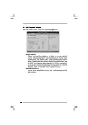
... You are allowed to enable this option as [Enabled], you will find the items "Target CPU Temperature" and "Target Fan Speed" appear to identify the temperature of the CPU temperature, motherboard temperature, CPU fan speed, chassis fan speed, and the critical voltage. The default value is [Disabled]. Target... set this function only when you adjusting them. 3.5 Hardware Health Event Monitoring Screen In this option as [Disabled], the CPU fan will operate in full speed. BIOS SETUP UTILITY Main OC Tweaker Advanced H/W Monitor Boot Security Exit Hardware Health Event Monitoring...
... You are allowed to enable this option as [Enabled], you will find the items "Target CPU Temperature" and "Target Fan Speed" appear to identify the temperature of the CPU temperature, motherboard temperature, CPU fan speed, chassis fan speed, and the critical voltage. The default value is [Disabled]. Target... set this function only when you adjusting them. 3.5 Hardware Health Event Monitoring Screen In this option as [Disabled], the CPU fan will operate in full speed. BIOS SETUP UTILITY Main OC Tweaker Advanced H/W Monitor Boot Security Exit Hardware Health Event Monitoring...


