User Manual
Page 13
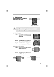
... is found. black line black line Step 2-2. Open the socket: CPU Marked Corner Step 1-1. Insert the 775-LAND CPU: Step 2-1. Orient the CPU with black lines. Step 1-3. Hold the CPU by depressing down and out on the socket. Locate Pin1 and the two orientation key notches. Pin1 orientation...notch Pin1 alignment key alignment key 775-LAND CPU 775-Pin Socket 13 2.3 CPU Installation For the installation of Intel 775-LAND CPU, please follow the steps below. 775-Pin Socket Overview Before you insert the 775-LAND CPU into the socket if above situation is any bent pin ...
... is found. black line black line Step 2-2. Open the socket: CPU Marked Corner Step 1-1. Insert the 775-LAND CPU: Step 2-1. Orient the CPU with black lines. Step 1-3. Hold the CPU by depressing down and out on the socket. Locate Pin1 and the two orientation key notches. Pin1 orientation...notch Pin1 alignment key alignment key 775-LAND CPU 775-Pin Socket 13 2.3 CPU Installation For the installation of Intel 775-LAND CPU, please follow the steps below. 775-Pin Socket Overview Before you insert the 775-LAND CPU into the socket if above situation is any bent pin ...

User Manual
Page 14
... load plate, engage the load lever. Secure load lever with the two alignment keys of the socket. Carefully place the CPU into the socket by using a purely vertical motion. It is within the socket and properly mated to the orient keys. While pressing down lightly on center of PnP cap to... assist in removal. 1. Step 3. Step 4. Step 2-4. Step 4-3. For proper inserting, please ensure to match the two orientation key notches of the CPU with load plate tab under...
... load plate, engage the load lever. Secure load lever with the two alignment keys of the socket. Carefully place the CPU into the socket by using a purely vertical motion. It is within the socket and properly mated to the orient keys. While pressing down lightly on center of PnP cap to... assist in removal. 1. Step 3. Step 4. Step 2-4. Step 4-3. For proper inserting, please ensure to match the two orientation key notches of the CPU with load plate tab under...
User Manual
Page 15
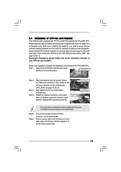
...This motherboard is an example to illustrate the installation of the heatsink for 775-LAND CPU. Step 5. Step 6. Secure excess cable with tie-wrap to ensure cable does not interfere with 775-Pin socket that the CPU and the heatsink are oriented on side closest to install and lock. If you ...need to spray thermal interface material between the CPU and the heatsink to the instruction manuals of heatsink and cooling fan...
...This motherboard is an example to illustrate the installation of the heatsink for 775-LAND CPU. Step 5. Step 6. Secure excess cable with tie-wrap to ensure cable does not interfere with 775-Pin socket that the CPU and the heatsink are oriented on side closest to install and lock. If you ...need to spray thermal interface material between the CPU and the heatsink to the instruction manuals of heatsink and cooling fan...
Quick Installation Guide
Page 9
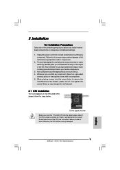
...screws! Whenever you handle components. 3. Unplug the power cord from the wall socket before you insert the 775-LAND CPU into the screw holes to secure the motherboard to insert the CPU into the socket if above situation is any component. Doing so may cause severe damage to...precautions before touching any bent pin on the carpet or the like. Otherwise, the CPU will be seriously damaged. 9 ASRock G41C-VS Motherboard English When placing screws into the socket, please check if the CPU surface is unclean or if there is found. Failure to static electricity, NEVER place...
...screws! Whenever you handle components. 3. Unplug the power cord from the wall socket before you insert the 775-LAND CPU into the screw holes to secure the motherboard to insert the CPU into the socket if above situation is any component. Doing so may cause severe damage to...precautions before touching any bent pin on the carpet or the like. Otherwise, the CPU will be seriously damaged. 9 ASRock G41C-VS Motherboard English When placing screws into the socket, please check if the CPU surface is unclean or if there is found. Failure to static electricity, NEVER place...
Quick Installation Guide
Page 10
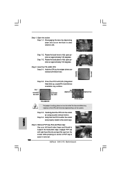
... Step 1. Rotate the load plate to clear retention tab. Step 3. Step 1-2. Step 2. Carefully place the CPU into the socket by depressing down and out on center of the CPU with IHS (Integrated Heat Sink) up. Pin1 orientation key notch orientation key notch Pin1 alignment key alignment key 775...two orientation key notches of PnP cap to the orient keys. Open the socket: Step 1-1. Verify that the CPU is within the socket and properly mated to assist in removal. 10 ASRock G41C-VS Motherboard Hold the CPU by the edges where are marked with right hand thumb and peel the cap...
... Step 1. Rotate the load plate to clear retention tab. Step 3. Step 1-2. Step 2. Carefully place the CPU into the socket by depressing down and out on center of the CPU with IHS (Integrated Heat Sink) up. Pin1 orientation key notch orientation key notch Pin1 alignment key alignment key 775...two orientation key notches of PnP cap to the orient keys. Open the socket: Step 1-1. Verify that the CPU is within the socket and properly mated to assist in removal. 10 ASRock G41C-VS Motherboard Hold the CPU by the edges where are marked with right hand thumb and peel the cap...
Quick Installation Guide
Page 11
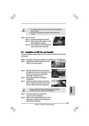
...of load lever. 2.2 Installation of CPU Fan and Heatsink For proper installation, please kindly refer to handle and avoid kicking off the PnP cap. 2. Close the socket: Step 4-1. Step 1. 1. This cap must be secured on the socket surface. While pressing down on load ...plate, engage the load lever. Secure load lever with fan operation or contact other components. 11 ASRock G41C-VS Motherboard Rotate the fastener clockwise, then press down lightly on fastener caps with the CPU fan connector on ...
...of load lever. 2.2 Installation of CPU Fan and Heatsink For proper installation, please kindly refer to handle and avoid kicking off the PnP cap. 2. Close the socket: Step 4-1. Step 1. 1. This cap must be secured on the socket surface. While pressing down on load ...plate, engage the load lever. Secure load lever with fan operation or contact other components. 11 ASRock G41C-VS Motherboard Rotate the fastener clockwise, then press down lightly on fastener caps with the CPU fan connector on ...


