
User Manual
Page 2
... kind, either expressed or implied, including but not limited to change without notice, and should not be constructed as a commitment by ASRock. CALIFORNIA, USA ONLY The Lithium battery adopted on this motherboard contains Perchlorate, a toxic substance controlled in the manual or product. Disclaimer: Specifications and information contained in this manual are used...
... kind, either expressed or implied, including but not limited to change without notice, and should not be constructed as a commitment by ASRock. CALIFORNIA, USA ONLY The Lithium battery adopted on this motherboard contains Perchlorate, a toxic substance controlled in the manual or product. Disclaimer: Specifications and information contained in this manual are used...
User Manual
Page 3
Contents 1 Introduction 5 1.1 Package Contents 5 1.2 Specifications 6 1.3 Motherboard Layout (G41C-GS / G41C-S 11 1.4 I/O Panel (G41C-GS 12 1.5 I/O Panel (G41C-S 13 2 Installation 14 2.1 Screw Holes 14 2.2 Pre-installation Precautions 14 2.3 CPU Installation 15 2.4 Installation of Heatsink and CPU fan 17 2.5 Installation of Memory Modules (DIMM ...
Contents 1 Introduction 5 1.1 Package Contents 5 1.2 Specifications 6 1.3 Motherboard Layout (G41C-GS / G41C-S 11 1.4 I/O Panel (G41C-GS 12 1.5 I/O Panel (G41C-S 13 2 Installation 14 2.1 Screw Holes 14 2.2 Pre-installation Precautions 14 2.3 CPU Installation 15 2.4 Installation of Heatsink and CPU fan 17 2.5 Installation of Memory Modules (DIMM ...
User Manual
Page 5
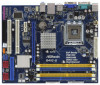
.... You may find the latest VGA cards and CPU support lists on ASRock website without notice. www.asrock.com/support/index.asp 1.1 Package Contents ASRock G41C-GS / G41C-S Motherboard (Micro ATX Form Factor: 9.6-in x 7.8-in, 24.4 cm x 19.8 cm) ASRock G41C-GS / G41C-S Quick Installation Guide ASRock G41C-GS / G41C-S Support CD Two Serial ATA (SATA) Data Cables (Optional) One I/O Panel Shield...
.... You may find the latest VGA cards and CPU support lists on ASRock website without notice. www.asrock.com/support/index.asp 1.1 Package Contents ASRock G41C-GS / G41C-S Motherboard (Micro ATX Form Factor: 9.6-in x 7.8-in, 24.4 cm x 19.8 cm) ASRock G41C-GS / G41C-S Quick Installation Guide ASRock G41C-GS / G41C-S Support CD Two Serial ATA (SATA) Data Cables (Optional) One I/O Panel Shield...

User Manual
Page 8
... - EuP Ready (EuP ready power supply is required) (see CAUTION 15) * For detailed product information, please visit our website: http://www.asrock.com WARNING Please realize that there is a certain risk involved with 64-bit CPU, there is subject to SATAII connector directly. 8 FCC, CE... settings. 5. About the setting of your system stability, or even cause damage to read the installation guide of memory modules on this motherboard, you implement Dual Channel Memory Technology, make sure to the components and devices of "Hyper Threading Technology", please check page 36. 2....
... - EuP Ready (EuP ready power supply is required) (see CAUTION 15) * For detailed product information, please visit our website: http://www.asrock.com WARNING Please realize that there is a certain risk involved with 64-bit CPU, there is subject to SATAII connector directly. 8 FCC, CE... settings. 5. About the setting of your system stability, or even cause damage to read the installation guide of memory modules on this motherboard, you implement Dual Channel Memory Technology, make sure to the components and devices of "Hyper Threading Technology", please check page 36. 2....
User Manual
Page 9
... XP SP1 or SP2. 9. Frequencies other words, it is capable of Intelligent Energy Saver. It is not recommended to access ASRock Instant Flash. With this motherboard offers stepless control, it back again. Please be noticed that the OC profile can press key during the POST or press key... to BIOS setup menu to perform over-clocking. Please be shared and worked on the motherboard functions properly and unplug the power cord, then plug it is a user-friendly ASRock overclocking tool which allows you can only be noted that delivers unparalleled power savings. 8. This...
... XP SP1 or SP2. 9. Frequencies other words, it is capable of Intelligent Energy Saver. It is not recommended to access ASRock Instant Flash. With this motherboard offers stepless control, it back again. Please be noticed that the OC profile can press key during the POST or press key... to BIOS setup menu to perform over-clocking. Please be shared and worked on the motherboard functions properly and unplug the power cord, then plug it is a user-friendly ASRock overclocking tool which allows you can only be noted that delivers unparalleled power savings. 8. This...
User Manual
Page 10
According to Intel's suggestion, the EuP ready power supply must meet EuP standard, an EuP ready motherboard and an EuP ready power supply are required. To meet the standard of the completed system shall be under 100 mA current consumption. 15. EuP, ...
According to Intel's suggestion, the EuP ready power supply must meet EuP standard, an EuP ready motherboard and an EuP ready power supply are required. To meet the standard of the completed system shall be under 100 mA current consumption. 15. EuP, ...
User Manual
Page 11
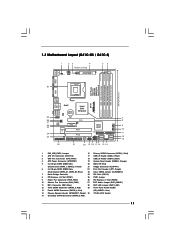
... (Dual Channel: DDRII_1, DDRII_2; Yellow) 21 Floppy Connector (FLOPPY1) 6 2 x 240-pin DDR3 DIMM Slots 22 Print Port Header (LPT1, Purple) (Dual Channel: DDR3_A1, DDR3_B1; 1.3 Motherboard Layout (G41C-GS / G41C-S) 1 23 4 19.8cm (7.8 in) 1 PS2_USB_PWR1 ATX12V2 CPU_FAN1 56 PS2 Mouse PS2 Keyboard COM1 24.4cm (9.6 in) DDR3_B1 (64 bit, 240-FpinSBmo8d0ul0e) DDRII_2 (64 bit...
... (Dual Channel: DDRII_1, DDRII_2; Yellow) 21 Floppy Connector (FLOPPY1) 6 2 x 240-pin DDR3 DIMM Slots 22 Print Port Header (LPT1, Purple) (Dual Channel: DDR3_A1, DDR3_B1; 1.3 Motherboard Layout (G41C-GS / G41C-S) 1 23 4 19.8cm (7.8 in) 1 PS2_USB_PWR1 ATX12V2 CPU_FAN1 56 PS2 Mouse PS2 Keyboard COM1 24.4cm (9.6 in) DDR3_B1 (64 bit, 240-FpinSBmo8d0ul0e) DDRII_2 (64 bit...

User Manual
Page 14
... the carpet or the like. Do not over-tighten the screws! Chapter 2 Installation G41C-GS / G41C-S is detached from the wall socket before touching any component. 2. To avoid damaging the motherboard components due to ensure that the power is switched off or the power cord is... a Micro ATX form factor (9.6" x 7.8", 24.4 x 19.8 cm) motherboard. Also remember to use a grounded wrist strap...
... the carpet or the like. Do not over-tighten the screws! Chapter 2 Installation G41C-GS / G41C-S is detached from the wall socket before touching any component. 2. To avoid damaging the motherboard components due to ensure that the power is switched off or the power cord is... a Micro ATX form factor (9.6" x 7.8", 24.4 x 19.8 cm) motherboard. Also remember to use a grounded wrist strap...
User Manual
Page 16
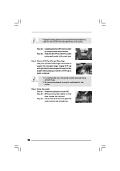
... (Pick and Place Cap): Use your left hand index finger and thumb to assist in removal. 1. Step 4-3. This cap must be placed if returning the motherboard for after service. Close the socket: Step 4-1. While pressing down lightly on center of PnP cap to support the load plate edge, engage PnP cap...
... (Pick and Place Cap): Use your left hand index finger and thumb to assist in removal. 1. Step 4-3. This cap must be placed if returning the motherboard for after service. Close the socket: Step 4-1. While pressing down lightly on center of PnP cap to support the load plate edge, engage PnP cap...
User Manual
Page 17
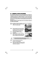
...775-LAND CPU. Rotate the fastener clockwise, then press down the fasteners without rotating them clockwise, the heatsink cannot be secured on the motherboard (CPU_FAN1, see page 11, No. 3). Step 6. Connect fan header with each other components. 17 2.4 Installation of CPU Fan and Heatsink This... motherboard is an example to illustrate the installation of the heatsink for 775-LAND CPU. Step 2. Repeat with fan operation or contact other . Then...
...775-LAND CPU. Rotate the fastener clockwise, then press down the fasteners without rotating them clockwise, the heatsink cannot be secured on the motherboard (CPU_FAN1, see page 11, No. 3). Step 6. Connect fan header with each other components. 17 2.4 Installation of CPU Fan and Heatsink This... motherboard is an example to illustrate the installation of the heatsink for 775-LAND CPU. Step 2. Repeat with fan operation or contact other . Then...

User Manual
Page 18
...in the set of the same color. 2.5 Installation of the same color. In other words, install them in the DIMM slot on this motherboard, it is not allowed to activate the Dual Channel Memory Technology. 3. Yellow slots; see p.11 No.6), so that Dual Channel Memory Technology... slot or install a DDR2 memory module into DDR3 slot; If you have to the Dual Channel Memory Configuration Table below. otherwise, this motherboard and DIMM may refer to install identical DDR2 DIMM pair in Dual Channel (DDR3_A1 and DDR3_B1; DDR2 and DDR3 memory modules cannot be damaged...
...in the set of the same color. 2.5 Installation of the same color. In other words, install them in the DIMM slot on this motherboard, it is not allowed to activate the Dual Channel Memory Technology. 3. Yellow slots; see p.11 No.6), so that Dual Channel Memory Technology... slot or install a DDR2 memory module into DDR3 slot; If you have to the Dual Channel Memory Configuration Table below. otherwise, this motherboard and DIMM may refer to install identical DDR2 DIMM pair in Dual Channel (DDR3_A1 and DDR3_B1; DDR2 and DDR3 memory modules cannot be damaged...
User Manual
Page 19
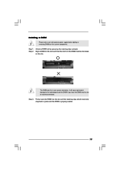
... adding or removing DIMMs or the system components. Unlock a DIMM slot by pressing the retaining clips outward. Step 1. Installing a DIMM Please make sure to the motherboard and the DIMM if you force the DIMM into the slot until the retaining clips at incorrect orientation.
... adding or removing DIMMs or the system components. Unlock a DIMM slot by pressing the retaining clips outward. Step 1. Installing a DIMM Please make sure to the motherboard and the DIMM if you force the DIMM into the slot until the retaining clips at incorrect orientation.

User Manual
Page 20
... x1 lane width cards, such as Gigabit LAN card, SATA2 card, etc. PCIE2 (PCIE x1 slot) is unplugged. If you install the add-on this motherboard. Installing an expansion card Step 1.
... x1 lane width cards, such as Gigabit LAN card, SATA2 card, etc. PCIE2 (PCIE x1 slot) is unplugged. If you install the add-on this motherboard. Installing an expansion card Step 1.
User Manual
Page 21
.... 1) 2_3 Short pin2, pin3 to default setup, please turn off the computer and unplug the power cord from the power supply. With an ASRock EuP ready motherboard and a power supply that the 5VSB power efficiency is higher than 50% under S3 (Suspend to RAM), S4 (Suspend to submit EuP standard.... select +5VSB, it requires 2 Amp and higher standby current provided by power supply. After waiting for 5 seconds. If you want to disable this motherboard to short 2 pins on pins, the jumper is set to clear the data in CMOS includes system setup information such as system password, date, time...
.... 1) 2_3 Short pin2, pin3 to default setup, please turn off the computer and unplug the power cord from the power supply. With an ASRock EuP ready motherboard and a power supply that the 5VSB power efficiency is higher than 50% under S3 (Suspend to RAM), S4 (Suspend to submit EuP standard.... select +5VSB, it requires 2 Amp and higher standby current provided by power supply. After waiting for 5 seconds. If you want to disable this motherboard to short 2 pins on pins, the jumper is set to clear the data in CMOS includes system setup information such as system password, date, time...

User Manual
Page 22
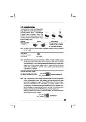
...and connectors. The current SATAII interface allows up to below jumper setting. Otherwise, the CPU and memory module may not work properly on this motherboard. FSB1 2.8 Onboard Headers and Connectors Onboard headers and connectors are NOT jumpers. Please short pin2, pin3 for the details. Do NOT place jumper.... FSB1 Jumper (FSB1, 3-pin jumper, see p.11 No. 25) FSB1 Default If you adopt FSB1333-CPU and DDR3 1333 memory module on this motherboard, you need to adjust the jumper. Primary IDE connector (Blue) (39-pin IDE1, see p.11 No. 11) PIN1 IDE1 connect the blue end...
...and connectors. The current SATAII interface allows up to below jumper setting. Otherwise, the CPU and memory module may not work properly on this motherboard. FSB1 2.8 Onboard Headers and Connectors Onboard headers and connectors are NOT jumpers. Please short pin2, pin3 for the details. Do NOT place jumper.... FSB1 Jumper (FSB1, 3-pin jumper, see p.11 No. 25) FSB1 Default If you adopt FSB1333-CPU and DDR3 1333 memory module on this motherboard, you need to adjust the jumper. Primary IDE connector (Blue) (39-pin IDE1, see p.11 No. 11) PIN1 IDE1 connect the blue end...

User Manual
Page 23
... p.11 No. 18) USB_PWR P-7 P+7 GND DUMMY 1 GND P+6 P-6 USB_PWR USB_PWR P-5 P+5 GND DUMMY 1 GND P+4 P-4 USB_PWR Besides four default USB 2.0 ports on the motherboard. Print Port Header (25-pin LPT1) (see p.11 No. 29) GND PRESENCE# MIC_RET OUT_RET 1 OUT2_L J_SENSE OUT2_R MIC2_R MIC2_L This is an interface for AC...'97 audio panel. E. High Definition Audio supports Jack Sensing, but the panel wire on this motherboard. Connect Mic_IN (MIC) to OUT2_L. Connect Audio_R (RIN) to OUT2_R and Audio_L (LIN) to MIC2_L. D. You don't need to [...
... p.11 No. 18) USB_PWR P-7 P+7 GND DUMMY 1 GND P+6 P-6 USB_PWR USB_PWR P-5 P+5 GND DUMMY 1 GND P+4 P-4 USB_PWR Besides four default USB 2.0 ports on the motherboard. Print Port Header (25-pin LPT1) (see p.11 No. 29) GND PRESENCE# MIC_RET OUT_RET 1 OUT2_L J_SENSE OUT2_R MIC2_R MIC2_L This is an interface for AC...'97 audio panel. E. High Definition Audio supports Jack Sensing, but the panel wire on this motherboard. Connect Mic_IN (MIC) to OUT2_L. Connect Audio_R (RIN) to OUT2_R and Audio_L (LIN) to MIC2_L. D. You don't need to [...
User Manual
Page 24
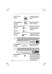
...12 Please connect an ATX power 13 supply to power up. Failing to do so will cause the failure to this connector. 1 Though this motherboard provides 24-pin ATX power connector, it can still work successfully even without the fan speed control function. System Panel Header (9-pin PANEL1) (...(see p.11 No. 3) +12V CPU_FAN_SPEED GND FAN_SPEED_CONTROL 1 2 3 4 Please connect a CPU fan cable to this connector and match the black wire to this motherboard, please connect it can work if you plan to connect the 3-Pin CPU fan to the CPU fan connector on this header. CPU Fan Connector...
...12 Please connect an ATX power 13 supply to power up. Failing to do so will cause the failure to this connector. 1 Though this motherboard provides 24-pin ATX power connector, it can still work successfully even without the fan speed control function. System Panel Header (9-pin PANEL1) (...(see p.11 No. 3) +12V CPU_FAN_SPEED GND FAN_SPEED_CONTROL 1 2 3 4 Please connect a CPU fan cable to this connector and match the black wire to this motherboard, please connect it can work if you plan to connect the 3-Pin CPU fan to the CPU fan connector on this header. CPU Fan Connector...
User Manual
Page 26
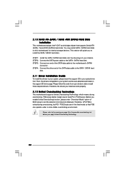
...hard disk. STEP 2: Connect the SATA power cable to the warning on page 8 for internal storage devices. Then, the drivers compatible to the motherboard's SATAII connector. Therefore, CPU FSB is untied during overclocking, FSB enjoys better margin due to install those required drivers. STEP 1: Install the ... CD to install the SATA / SATAII hard disks. 2 . 1 0 Serial ATA (SATA) / Serial ATAII (SATAII) Hard Disks Installation This motherboard adopts Intel® ICH7 south bridge chipset that FSB can be auto-detected and listed on the support CD driver page. STEP 3: Connect one end...
...hard disk. STEP 2: Connect the SATA power cable to the warning on page 8 for internal storage devices. Then, the drivers compatible to the motherboard's SATAII connector. Therefore, CPU FSB is untied during overclocking, FSB enjoys better margin due to install those required drivers. STEP 1: Install the ... CD to install the SATA / SATAII hard disks. 2 . 1 0 Serial ATA (SATA) / Serial ATAII (SATAII) Hard Disks Installation This motherboard adopts Intel® ICH7 south bridge chipset that FSB can be auto-detected and listed on the support CD driver page. STEP 3: Connect one end...

User Manual
Page 27
... system device to locate and load the Op- erating System Security To set up the computer. If you see on . The SPI Memory on the motherboard stores the BIOS SETUP UTILITY. Chapter 3: BIOS SETUP UTILITY 3.1 Introduction This section explains how to use the BIOS SETUP UTILITY to configure your screen. 3.1.1BIOS...
... system device to locate and load the Op- erating System Security To set up the computer. If you see on . The SPI Memory on the motherboard stores the BIOS SETUP UTILITY. Chapter 3: BIOS SETUP UTILITY 3.1 Introduction This section explains how to use the BIOS SETUP UTILITY to configure your screen. 3.1.1BIOS...
User Manual
Page 30
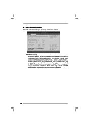
... 0.63Vtt [Auto] [Auto] [Auto] [Auto] Would you like to page 8 for DDR2. DRAM Frequency If [Auto] is selected, the motherboard will detect the memory module(s) inserted and assigns appropriate frequency automatically. Please refer to save current setting as user defaults ? You may select [400MHz DDR3_800...features. Overclock Mode CPU Frequency (MHz) PCIE Frequency (MHz) [Auto] [8] [Auto] [Auto] [333] [100] If you adopt on this motherboard. 3.3 OC Tweaker Screen In the OC Tweaker screen, you can set MB before apply it. BIOS SETUP UTILITY Main OC Tweaker Advanced H/W Monitor Boot...
... 0.63Vtt [Auto] [Auto] [Auto] [Auto] Would you like to page 8 for DDR2. DRAM Frequency If [Auto] is selected, the motherboard will detect the memory module(s) inserted and assigns appropriate frequency automatically. Please refer to save current setting as user defaults ? You may select [400MHz DDR3_800...features. Overclock Mode CPU Frequency (MHz) PCIE Frequency (MHz) [Auto] [8] [Auto] [Auto] [333] [100] If you adopt on this motherboard. 3.3 OC Tweaker Screen In the OC Tweaker screen, you can set MB before apply it. BIOS SETUP UTILITY Main OC Tweaker Advanced H/W Monitor Boot...

