
User Manual
Page 1
All rights reserved. 1 G41C-GS / G41C-S User Manual Version 1.0 Published December 2009 Copyright©2009 ASRock INC.
All rights reserved. 1 G41C-GS / G41C-S User Manual Version 1.0 Published December 2009 Copyright©2009 ASRock INC.

User Manual
Page 2
... and corporate names appearing in this device must accept any defect or error in advance. With respect to the contents of this manual, ASRock does not provide warranty of any kind, either expressed or implied, including but not limited to the following two conditions: (1) ...explanation and to the owners' benefit, without intent to change without written consent of documentation by ASRock. CALIFORNIA, USA ONLY The Lithium battery adopted on this manual. ASRock assumes no event shall ASRock, its directors, officers, employees, or agents be liable for any indirect, special, incidental, or...
... and corporate names appearing in this device must accept any defect or error in advance. With respect to the contents of this manual, ASRock does not provide warranty of any kind, either expressed or implied, including but not limited to the following two conditions: (1) ...explanation and to the owners' benefit, without intent to change without written consent of documentation by ASRock. CALIFORNIA, USA ONLY The Lithium battery adopted on this manual. ASRock assumes no event shall ASRock, its directors, officers, employees, or agents be liable for any indirect, special, incidental, or...
User Manual
Page 5
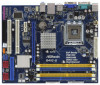
....asp 1.1 Package Contents ASRock G41C-GS / G41C-S Motherboard (Micro ATX Form Factor: 9.6-in x 7.8-in, 24.4 cm x 19.8 cm) ASRock G41C-GS / G41C-S Quick Installation Guide ASRock G41C-GS / G41C-S Support CD Two Serial ATA (SATA) Data Cables (Optional) One I/O Panel Shield 5 In this manual, chapter 1 and 2 contain introduction of this motherboard, please visit our website for purchasing ASRock G41C-GS / G41C-S motherboard, a reliable...
....asp 1.1 Package Contents ASRock G41C-GS / G41C-S Motherboard (Micro ATX Form Factor: 9.6-in x 7.8-in, 24.4 cm x 19.8 cm) ASRock G41C-GS / G41C-S Quick Installation Guide ASRock G41C-GS / G41C-S Support CD Two Serial ATA (SATA) Data Cables (Optional) One I/O Panel Shield 5 In this manual, chapter 1 and 2 contain introduction of this motherboard, please visit our website for purchasing ASRock G41C-GS / G41C-S motherboard, a reliable...
User Manual
Page 17
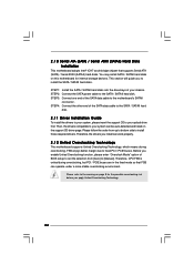
... the fasteners without rotating them clockwise, the heatsink cannot be secured on the socket surface. Step 6. Secure excess cable with tie-wrap to the instruction manuals of IHS on the motherboard. Below is equipped with fan operation or contact other . Step 4. 2.4 Installation of CPU Fan and Heatsink This motherboard is an...
... the fasteners without rotating them clockwise, the heatsink cannot be secured on the socket surface. Step 6. Secure excess cable with tie-wrap to the instruction manuals of IHS on the motherboard. Below is equipped with fan operation or contact other . Step 4. 2.4 Installation of CPU Fan and Heatsink This motherboard is an...

User Manual
Page 23
...) to OUT2_L. MIC_RET and OUT_RET are two USB 2.0 headers on the I/O panel, there are for AC'97 audio panel. Please follow the instruction in our manual and chassis manual to connect them for HD audio panel only. You don't need to install your system. 2. C.
...) to OUT2_L. MIC_RET and OUT_RET are two USB 2.0 headers on the I/O panel, there are for AC'97 audio panel. Please follow the instruction in our manual and chassis manual to connect them for HD audio panel only. You don't need to install your system. 2. C.
User Manual
Page 26
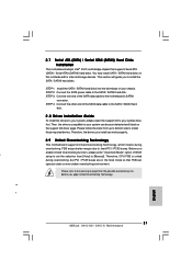
... and listed on this motherboard for the possible overclocking risk before you to the SATA / SATAII hard disk. Please follow the order from [Auto] to [Manual]. Before you install can operate under a more stable overclocking environment. STEP 2: Connect the SATA power cable to install the SATA / SATAII hard disks. Therefore, the...
... and listed on this motherboard for the possible overclocking risk before you to the SATA / SATAII hard disk. Please follow the order from [Auto] to [Manual]. Before you install can operate under a more stable overclocking environment. STEP 2: Connect the SATA power cable to install the SATA / SATAII hard disks. Therefore, the...

User Manual
Page 32
... Overclock Mode. VTT Voltage Use this to enable this function. Please note that enabling this option to [Disable] if above issue occurs. Configuration options: [Auto], [Manual] and [Optimized]. Intel (R) SpeedStep(tm) tech. Configuration options: [Auto], [Enabled] and [Disabled]. The default value of this item to adjust CPU frequency. Ratio CMOS Setting...
... Overclock Mode. VTT Voltage Use this to enable this function. Please note that enabling this option to [Disable] if above issue occurs. Configuration options: [Auto], [Manual] and [Optimized]. Intel (R) SpeedStep(tm) tech. Configuration options: [Auto], [Enabled] and [Disabled]. The default value of this item to adjust CPU frequency. Ratio CMOS Setting...

User Manual
Page 35
... adjust CPU frequency. Spread Spectrum This item should always be hidden if the installed CPU does not support Intel (R) Virtualization Technology. 35 Configuration options: [Auto], [Manual] and [Optimized]. On-Demand Clock Modulation [Auto] [333] [100] [Enabled] [Auto] [8] [Disabled] [Enabled] [Enabled] [Disabled] [Auto] [Auto] Select the over clock mode. +F1 F9 F10...
... adjust CPU frequency. Spread Spectrum This item should always be hidden if the installed CPU does not support Intel (R) Virtualization Technology. 35 Configuration options: [Auto], [Manual] and [Optimized]. On-Demand Clock Modulation [Auto] [333] [100] [Enabled] [Auto] [8] [Disabled] [Enabled] [Enabled] [Disabled] [Auto] [Auto] Select the over clock mode. +F1 F9 F10...
Quick Installation Guide
Page 5
... the motherboard can be found in the user manual presented in , 24.4 cm x 19.8 cm) ASRock G41C-GS / G41C-S Quick Installation Guide ASRock G41C-GS / G41C-S Support CD Two Serial ATA (SATA) Data Cables (Optional) One I/O Panel Shield English 5 ASRock G41C-GS / G41C-S Motherboard www.asrock.com/support/index.asp 1.1 Package Contents ASRock G41C-GS / G41C-S Motherboard (Micro ATX Form Factor: 9.6-in x 7.8-in the...
... the motherboard can be found in the user manual presented in , 24.4 cm x 19.8 cm) ASRock G41C-GS / G41C-S Quick Installation Guide ASRock G41C-GS / G41C-S Support CD Two Serial ATA (SATA) Data Cables (Optional) One I/O Panel Shield English 5 ASRock G41C-GS / G41C-S Motherboard www.asrock.com/support/index.asp 1.1 Package Contents ASRock G41C-GS / G41C-S Motherboard (Micro ATX Form Factor: 9.6-in x 7.8-in the...
Quick Installation Guide
Page 8
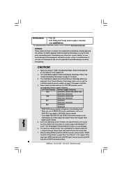
...We are not responsible for details. 3. CAUTION! 1. This motherboard supports Dual Channel Memory Technology. Due to SATAII connector directly. 8 ASRock G41C-GS / G41C-S Motherboard English Before installing SATAII hard disk to change. Before you use a FSB533-CPU on this motherboard, it will operate in...of "User Manual" in the BIOS, applying Untied Overclocking Technology, or using the thirdparty overclocking tools. EuP Ready (EuP ready power supply is required) (see CAUTION 15) * For detailed product information, please visit our website: http://www.asrock.com WARNING...
...We are not responsible for details. 3. CAUTION! 1. This motherboard supports Dual Channel Memory Technology. Due to SATAII connector directly. 8 ASRock G41C-GS / G41C-S Motherboard English Before installing SATAII hard disk to change. Before you use a FSB533-CPU on this motherboard, it will operate in...of "User Manual" in the BIOS, applying Untied Overclocking Technology, or using the thirdparty overclocking tools. EuP Ready (EuP ready power supply is required) (see CAUTION 15) * For detailed product information, please visit our website: http://www.asrock.com WARNING...

Quick Installation Guide
Page 13
...fasteners. Step 4-2. Step 4-3. Repeat with the CPU fan connector on the motherboard. Step 5. Secure load lever with thumb to the instruction manuals of your CPU fan and heatsink. English Step 2. Rotate the fastener clockwise, then press down on the socket surface. While pressing down ... to use the cap tab to the CPU fan connector on the motherboard. Align fasteners with fan operation or contact other components. 13 ASRock G41C-GS / G41C-S Motherboard If you press down lightly on side closest to handle and avoid kicking off the PnP cap. 2. Step 6. Step 4. ...
...fasteners. Step 4-2. Step 4-3. Repeat with the CPU fan connector on the motherboard. Step 5. Secure load lever with thumb to the instruction manuals of your CPU fan and heatsink. English Step 2. Rotate the fastener clockwise, then press down on the socket surface. While pressing down ... to use the cap tab to the CPU fan connector on the motherboard. Align fasteners with fan operation or contact other components. 13 ASRock G41C-GS / G41C-S Motherboard If you press down lightly on side closest to handle and avoid kicking off the PnP cap. 2. Step 6. Step 4. ...
Quick Installation Guide
Page 19
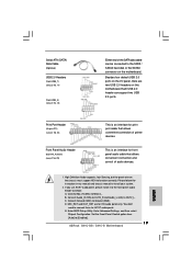
... for front panel audio cable that allows convenient connection of printer devices. Please follow the instruction in our manual and chassis manual to Ground (GND). B. Each USB 2.0 header can be connected to [Enabled]. 19 ASRock G41C-GS / G41C-S Motherboard English D. MIC_RET and OUT_RET are two USB 2.0 headers on the motherboard. Print Port Header (25-pin...
... for front panel audio cable that allows convenient connection of printer devices. Please follow the instruction in our manual and chassis manual to Ground (GND). B. Each USB 2.0 header can be connected to [Enabled]. 19 ASRock G41C-GS / G41C-S Motherboard English D. MIC_RET and OUT_RET are two USB 2.0 headers on the motherboard. Print Port Header (25-pin...
Quick Installation Guide
Page 21
... on this motherboard for the possible overclocking risk before you to [Manual]. STEP 3: Connect one end of the SATA data cable to the SATA / SATAII hard disk. 2.8 Driver Installation Guide To install the drivers to your chassis. English 21 ASRock G41C-GS / G41C-S Motherboard STEP 4: Connect the other end of the SATA data cable...
... on this motherboard for the possible overclocking risk before you to [Manual]. STEP 3: Connect one end of the SATA data cable to the SATA / SATAII hard disk. 2.8 Driver Installation Guide To install the drivers to your chassis. English 21 ASRock G41C-GS / G41C-S Motherboard STEP 4: Connect the other end of the SATA data cable...
Quick Installation Guide
Page 22
... the detailed information about BIOS Setup, please refer to display the menus. 22 ASRock G41C-GS / G41C-S Motherboard English BIOS Information The Flash Memory on the file "ASSETUP.EXE" from the BIN folder in the Support CD to the User Manual (PDF file) contained in your CDROM drive. otherwise, POST continues with the motherboard...
... the detailed information about BIOS Setup, please refer to display the menus. 22 ASRock G41C-GS / G41C-S Motherboard English BIOS Information The Flash Memory on the file "ASSETUP.EXE" from the BIN folder in the Support CD to the User Manual (PDF file) contained in your CDROM drive. otherwise, POST continues with the motherboard...
