User Manual
Page 3
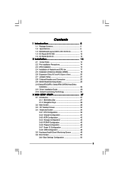
Contents 1 Introduction 5 1.1 Package Contents 5 1.2 Specifications 6 1.3 Motherboard Layout (G41C-GS / G41C-S 11 1.4 I/O Panel (G41C-GS 12 1.5 I/O Panel (G41C-S 13 2 Installation 14 2.1 Screw Holes 14 2.2 Pre-installation Precautions 14 2.3 CPU Installation 15 2.4 Installation of Heatsink and CPU fan 17 2.5 Installation of Memory Modules (DIMM 18 2.6 Expansion Slots (PCI and PCI Express Slots 20 2.7 Jumpers Setup 21 2.8 Onboard Headers and Connectors 22...
Contents 1 Introduction 5 1.1 Package Contents 5 1.2 Specifications 6 1.3 Motherboard Layout (G41C-GS / G41C-S 11 1.4 I/O Panel (G41C-GS 12 1.5 I/O Panel (G41C-S 13 2 Installation 14 2.1 Screw Holes 14 2.2 Pre-installation Precautions 14 2.3 CPU Installation 15 2.4 Installation of Heatsink and CPU fan 17 2.5 Installation of Memory Modules (DIMM 18 2.6 Expansion Slots (PCI and PCI Express Slots 20 2.7 Jumpers Setup 21 2.8 Onboard Headers and Connectors 22...

User Manual
Page 6
... processors - Dual Channel DDR3/DDR2 Memory Technology (see CAUTION 2) - capacity of system memory: 8GB (see CAUTION 5) - 2 x DDR2 DIMM slots - Max. G41C-GS: Realtek PCIE x1 Gigabit LAN RTL8111DL, speed 10/100/1000 Mb/s - Supports Wake-On-LAN I /O - Supports Untied Overclocking Technology (see CAUTION 3) - 2...; G41 - Southbridge: Intel® ICH7 - Pixel Shader 4.0, DirectX 10 - capacity of system memory: 8GB (see CAUTION 5) - 1 x PCI Express x16 slot - 1 x PCI Express x1 slot - 2 x PCI slots - Supports Hyper-Threading Technology (see CAUTION 4) - Max. Max.
... processors - Dual Channel DDR3/DDR2 Memory Technology (see CAUTION 2) - capacity of system memory: 8GB (see CAUTION 5) - 2 x DDR2 DIMM slots - Max. G41C-GS: Realtek PCIE x1 Gigabit LAN RTL8111DL, speed 10/100/1000 Mb/s - Supports Wake-On-LAN I /O - Supports Untied Overclocking Technology (see CAUTION 3) - 2...; G41 - Southbridge: Intel® ICH7 - Pixel Shader 4.0, DirectX 10 - capacity of system memory: 8GB (see CAUTION 5) - 1 x PCI Express x16 slot - 1 x PCI Express x1 slot - 2 x PCI slots - Supports Hyper-Threading Technology (see CAUTION 4) - Max. Max.
User Manual
Page 11
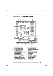
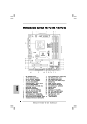
... Slot (PCIE1) 25 FSB1 Jumper 9 Power Fan Connector (PWR_FAN1) 26 PCI Express x1 Slot (PCIE2) 10 Chassis Fan Connector (CHA_FAN1) 27 EUP Audio Jumper (EUP_AUDIO1) 11 IDE1 Connector (IDE1, Blue) 28 EUP LAN Jumper (EUP_LAN1) 12 Third SATAII Connector (SATAII_3; 1.3 Motherboard Layout (G41C-GS / G41C-S) 1 23 4 19.8cm (7.8 in) 1 PS2_USB_PWR1 ATX12V2 CPU_FAN1 56 PS2...
... Slot (PCIE1) 25 FSB1 Jumper 9 Power Fan Connector (PWR_FAN1) 26 PCI Express x1 Slot (PCIE2) 10 Chassis Fan Connector (CHA_FAN1) 27 EUP Audio Jumper (EUP_AUDIO1) 11 IDE1 Connector (IDE1, Blue) 28 EUP LAN Jumper (EUP_LAN1) 12 Third SATAII Connector (SATAII_3; 1.3 Motherboard Layout (G41C-GS / G41C-S) 1 23 4 19.8cm (7.8 in) 1 PS2_USB_PWR1 ATX12V2 CPU_FAN1 56 PS2...
User Manual
Page 20
... cards with the slot and press firmly until the card is unplugged. Align the card connector with x16 lane width graphics cards. PCI slots: PCI slots are 2 PCI slots and 2 PCI Express slots on the slot. PCIE slots: PCIE1 (PCIE x16 slot) is used for the card before you start the installation. ... x1 slot) is used for later use . Fasten the card to PCIE1 (PCIE x16 slot), the onboard VGA will be disabled. 2.6 Expansion Slots (PCI and PCI Express Slots) There are used to install expansion cards that you intend to [Auto], then the onboard VGA will be enabled, and the primary screen...
... cards with the slot and press firmly until the card is unplugged. Align the card connector with x16 lane width graphics cards. PCI slots: PCI slots are 2 PCI slots and 2 PCI Express slots on the slot. PCIE slots: PCIE1 (PCIE x16 slot) is used for the card before you start the installation. ... x1 slot) is used for later use . Fasten the card to PCIE1 (PCIE x16 slot), the onboard VGA will be disabled. 2.6 Expansion Slots (PCI and PCI Express Slots) There are used to install expansion cards that you intend to [Auto], then the onboard VGA will be enabled, and the primary screen...
User Manual
Page 26
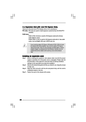
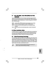
...data cable to install the SATA / SATAII hard disks. Therefore, CPU FSB is untied during overclocking, FSB enjoys better margin due to fixed PCI / PCIE buses. STEP 2: Connect the SATA power cable to your system, please insert the support CD to the SATA / SATAII hard ...overclocking risk before you install can work properly. 2 . 1 2 Untied Overclocking Technology This motherboard supports Untied Overclocking Technology, which means during overclocking, but PCI / PCIE buses are in the fixed mode so that supports Serial ATA (SATA) / Serial ATAII (SATAII) hard disks. You may install SATA /...
...data cable to install the SATA / SATAII hard disks. Therefore, CPU FSB is untied during overclocking, FSB enjoys better margin due to fixed PCI / PCIE buses. STEP 2: Connect the SATA power cable to your system, please insert the support CD to the SATA / SATAII hard ...overclocking risk before you install can work properly. 2 . 1 2 Untied Overclocking Technology This motherboard supports Untied Overclocking Technology, which means during overclocking, but PCI / PCIE buses are in the fixed mode so that supports Serial ATA (SATA) / Serial ATAII (SATAII) hard disks. You may install SATA /...
User Manual
Page 37
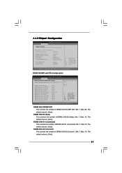
... DRAM DLL SKEW Configuration Fixed Mode Operation [Enabled] Intelligent Energy Saver Primary Graphics Adapter Shared Memory PAVP Mode DVMT Mode Select DVMT/FIXED Memory [Disabled] [PCI] [Auto] [Disabled] [DVMT Mode] [Maximum DVMT] Onboard HD Audio Front Panel OnBoard Lan [Auto] [Enabled] [Enabled] +F1 F9 F10 ESC Select Screen Select Item Change...
... DRAM DLL SKEW Configuration Fixed Mode Operation [Enabled] Intelligent Energy Saver Primary Graphics Adapter Shared Memory PAVP Mode DVMT Mode Select DVMT/FIXED Memory [Disabled] [PCI] [Auto] [Disabled] [DVMT Mode] [Maximum DVMT] Onboard HD Audio Front Panel OnBoard Lan [Auto] [Enabled] [Enabled] +F1 F9 F10 ESC Select Screen Select Item Change...
User Manual
Page 41
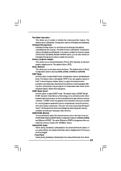
...plugged. If you can also choose our Intelligent Energy Saver utility to enable this function. Intelligent Energy Saver Intelligent Energy Saver is [PCI]. Primary Graphics Adapter This allows you set DVMT Mode Select as [DVMT Mode]. The default value is a revolutionary technology that offers...Share Memory This allows you adopt the memory module with other system components. PAVP Mode Use this item if you to select [Onboard], [PCI] or [PCI Express] as needed for the onboard HD Audio Front Panel. 41 Configuration options: [Disabled] and [Lite]. DVMT (Dynamic Video Memory ...
...plugged. If you can also choose our Intelligent Energy Saver utility to enable this function. Intelligent Energy Saver Intelligent Energy Saver is [PCI]. Primary Graphics Adapter This allows you set DVMT Mode Select as [DVMT Mode]. The default value is a revolutionary technology that offers...Share Memory This allows you adopt the memory module with other system components. PAVP Mode Use this item if you to select [Onboard], [PCI] or [PCI Express] as needed for the onboard HD Audio Front Panel. 41 Configuration options: [Disabled] and [Lite]. DVMT (Dynamic Video Memory ...
User Manual
Page 42
.../Power resumes and the system starts to boot up when the power recovers. Suspend to RAM Use this item to enable or disable PCI devices to enable or disable the "OnBoard Lan" feature. 3.4.3 ACPI Configuration BIOS SETUP UTILITY Advanced ACPI Configuration Suspend To RAM Restore ...on AC/Power Loss Ring-In Power On PCI Devices Power On PS / 2 Keyboard Power On RTC Alarm Power On ACPI HPET Table [Disabled] [Power Off] [Disabled] [Disabled] [Disabled] [Disabled...
.../Power resumes and the system starts to boot up when the power recovers. Suspend to RAM Use this item to enable or disable PCI devices to enable or disable the "OnBoard Lan" feature. 3.4.3 ACPI Configuration BIOS SETUP UTILITY Advanced ACPI Configuration Suspend To RAM Restore ...on AC/Power Loss Ring-In Power On PCI Devices Power On PS / 2 Keyboard Power On RTC Alarm Power On ACPI HPET Table [Disabled] [Power Off] [Disabled] [Disabled] [Disabled] [Disabled...
User Manual
Page 45
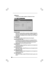
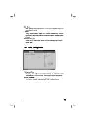
...Change Option General Help Load Defaults Save and Exit Exit v02.54 (C) Copyright 1985-2005, American Megatrends, Inc. PCI Latency Timer The default value is recommended to maximize the IDE hard disk data transfer rate. 3.4.5 PCIPnP Configuration BIOS SETUP UTILITY ...Advanced Advanced PCI / PnP Settings PCI Latency Timer PCI IDE BusMaster [32] [Enabled] Value in units of PCI clocks for compatible IDE devices. Configuration options: [Disabled], [Auto], [Enabled]. 32-Bit Data ...
...Change Option General Help Load Defaults Save and Exit Exit v02.54 (C) Copyright 1985-2005, American Megatrends, Inc. PCI Latency Timer The default value is recommended to maximize the IDE hard disk data transfer rate. 3.4.5 PCIPnP Configuration BIOS SETUP UTILITY ...Advanced Advanced PCI / PnP Settings PCI Latency Timer PCI IDE BusMaster [32] [Enabled] Value in units of PCI clocks for compatible IDE devices. Configuration options: [Disabled], [Auto], [Enabled]. 32-Bit Data ...
Quick Installation Guide
Page 2
... ASRock G41C-GS / G41C-S Motherboard Red) 29 Front Panel Audio Header 13 Fourth SATAII Connector (SATAII_4; Blue) 23 Clear CMOS Jumper (CLRCMOS1) 7 North Bridge Controller 24 PCI Slots (PCI1-2) 8 PCI Express x16 Slot (PCIE1) 25 FSB1 Jumper 9 Power Fan Connector (PWR_FAN1) 26 PCI ...HD_AUDIO1, Lime) 14 Chassis Speaker Header (SPEAKER 1, Purple) 30 775-Pin CPU Socket 15 Secondary SATAII Connector (SATAII_2; Motherboard Layout (G41C-GS / G41C-S) English 1 PS2_USB_PWR1 Jumper 16 Primary SATAII Connector (SATAII_1; Yellow) 21 Floppy Connector (FLOPPY1) 6 2 x 240-pin DDR3 DIMM...
... ASRock G41C-GS / G41C-S Motherboard Red) 29 Front Panel Audio Header 13 Fourth SATAII Connector (SATAII_4; Blue) 23 Clear CMOS Jumper (CLRCMOS1) 7 North Bridge Controller 24 PCI Slots (PCI1-2) 8 PCI Express x16 Slot (PCIE1) 25 FSB1 Jumper 9 Power Fan Connector (PWR_FAN1) 26 PCI ...HD_AUDIO1, Lime) 14 Chassis Speaker Header (SPEAKER 1, Purple) 30 775-Pin CPU Socket 15 Secondary SATAII Connector (SATAII_2; Motherboard Layout (G41C-GS / G41C-S) English 1 PS2_USB_PWR1 Jumper 16 Primary SATAII Connector (SATAII_1; Yellow) 21 Floppy Connector (FLOPPY1) 6 2 x 240-pin DDR3 DIMM...
Quick Installation Guide
Page 6
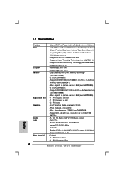
...: Intel® ICH7 - Supports DDR3 1333(OC)/1066/800 non-ECC, un-buffered memory (see CAUTION 5) - 1 x PCI Express x16 slot - 1 x PCI Express x1 slot - 2 x PCI slots - Max. Supports EM64T CPU - Supports Wake-On-LAN I /O - LGA 775 for Intel® CoreTM 2 Extreme ...1.2 Specifications Platform CPU Chipset Memory Expansion Slot Graphics Audio LAN Rear Panel I /O Panel - 1 x PS/2 Mouse Port - 1 x PS/2 Keyboard Port 6 ASRock G41C-GS / G41C-S Motherboard English Supports D-Sub with max. Micro ATX Form Factor: 9.6-in x 7.8-in, 24.4 cm x 19.8 cm - capacity of system memory: 8GB (see ...
...: Intel® ICH7 - Supports DDR3 1333(OC)/1066/800 non-ECC, un-buffered memory (see CAUTION 5) - 1 x PCI Express x16 slot - 1 x PCI Express x1 slot - 2 x PCI slots - Max. Supports EM64T CPU - Supports Wake-On-LAN I /O - LGA 775 for Intel® CoreTM 2 Extreme ...1.2 Specifications Platform CPU Chipset Memory Expansion Slot Graphics Audio LAN Rear Panel I /O Panel - 1 x PS/2 Mouse Port - 1 x PS/2 Keyboard Port 6 ASRock G41C-GS / G41C-S Motherboard English Supports D-Sub with max. Micro ATX Form Factor: 9.6-in x 7.8-in, 24.4 cm x 19.8 cm - capacity of system memory: 8GB (see ...
Quick Installation Guide
Page 16
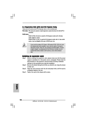
..., and the primary screen will be onboard VGA. Before installing the expansion card, please make necessary hardware settings for PCI Express cards with screws. 16 ASRock G41C-GS / G41C-S Motherboard English If you install the add-on PCI Express VGA card to PCIE1 (PCIE x16 slot) and adjust the BIOS options "Primary Graphics Adapter" to [Onboard...
..., and the primary screen will be onboard VGA. Before installing the expansion card, please make necessary hardware settings for PCI Express cards with screws. 16 ASRock G41C-GS / G41C-S Motherboard English If you install the add-on PCI Express VGA card to PCIE1 (PCIE x16 slot) and adjust the BIOS options "Primary Graphics Adapter" to [Onboard...
Quick Installation Guide
Page 21
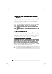
... to bottom side to install the SATA / SATAII hard disks. STEP 4: Connect the other end of the SATA data cable to fixed PCI / PCIE buses. Therefore, CPU FSB is untied during overclocking, FSB enjoys better margin due to the motherboard's SATAII connector. This section... during overclocking, but PCI / PCIE buses are in the fixed mode so that supports Serial ATA (SATA) / Serial ATAII (SATAII) hard disks. Please follow the order from [Auto] to the SATA / SATAII hard disk. Before you apply Untied Overclocking Technology. English 21 ASRock G41C-GS / G41C-S Motherboard You may ...
... to bottom side to install the SATA / SATAII hard disks. STEP 4: Connect the other end of the SATA data cable to fixed PCI / PCIE buses. Therefore, CPU FSB is untied during overclocking, FSB enjoys better margin due to the motherboard's SATAII connector. This section... during overclocking, but PCI / PCIE buses are in the fixed mode so that supports Serial ATA (SATA) / Serial ATAII (SATAII) hard disks. Please follow the order from [Auto] to the SATA / SATAII hard disk. Before you apply Untied Overclocking Technology. English 21 ASRock G41C-GS / G41C-S Motherboard You may ...
