User Manual
Page 3
Contents 1 Introduction 5 1.1 Package Contents 5 1.2 Specifications 6 1.3 Motherboard Layout (G41C-GS / G41C-S 11 1.4 I/O Panel (G41C-GS 12 1.5 I/O Panel (G41C-S 13 2 Installation 14 2.1 Screw Holes 14 2.2 Pre-installation Precautions 14 2.3 CPU Installation 15 2.4 Installation of Heatsink and CPU fan 17 2.5 Installation of Memory Modules (DIMM ...
Contents 1 Introduction 5 1.1 Package Contents 5 1.2 Specifications 6 1.3 Motherboard Layout (G41C-GS / G41C-S 11 1.4 I/O Panel (G41C-GS 12 1.5 I/O Panel (G41C-S 13 2 Installation 14 2.1 Screw Holes 14 2.2 Pre-installation Precautions 14 2.3 CPU Installation 15 2.4 Installation of Heatsink and CPU fan 17 2.5 Installation of Memory Modules (DIMM ...
User Manual
Page 5
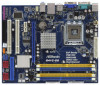
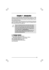
... manual, chapter 1 and 2 contain introduction of the Support CD. www.asrock.com/support/index.asp 1.1 Package Contents ASRock G41C-GS / G41C-S Motherboard (Micro ATX Form Factor: 9.6-in x 7.8-in, 24.4 cm x 19.8 cm) ASRock G41C-GS / G41C-S Quick Installation Guide ASRock G41C-GS / G41C-S Support CD Two Serial ATA (SATA) Data Cables (Optional) One I/O Panel Shield 5 Chapter 1 Introduction Thank you for specific information about the...
... manual, chapter 1 and 2 contain introduction of the Support CD. www.asrock.com/support/index.asp 1.1 Package Contents ASRock G41C-GS / G41C-S Motherboard (Micro ATX Form Factor: 9.6-in x 7.8-in, 24.4 cm x 19.8 cm) ASRock G41C-GS / G41C-S Quick Installation Guide ASRock G41C-GS / G41C-S Support CD Two Serial ATA (SATA) Data Cables (Optional) One I/O Panel Shield 5 Chapter 1 Introduction Thank you for specific information about the...

User Manual
Page 6
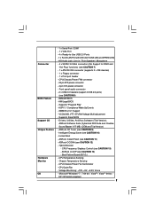
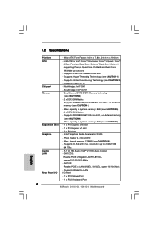
...DDR2 Memory Technology (see CAUTION 4) - Pixel Shader 4.0, DirectX 10 - shared memory 1759MB (see CAUTION 5) - 2 x DDR2 DIMM slots - G41C-GS: Realtek PCIE x1 Gigabit LAN RTL8111DL, speed 10/100/1000 Mb/s - Southbridge: Intel® ICH7 - capacity of system memory: 8GB (see ...processors - Supports Hyper-Threading Technology (see CAUTION 4) - Supports D-Sub with max. 1.2 Specifications Platform CPU Chipset Memory Expansion Slot Graphics Audio LAN Rear Panel I /O Panel - 1 x PS/2 Mouse Port - 1 x PS/2 Keyboard Port 6 Supports FSB1333/1066/800/533 MHz - Northbridge: Intel® G41 - ...
...DDR2 Memory Technology (see CAUTION 4) - Pixel Shader 4.0, DirectX 10 - shared memory 1759MB (see CAUTION 5) - 2 x DDR2 DIMM slots - G41C-GS: Realtek PCIE x1 Gigabit LAN RTL8111DL, speed 10/100/1000 Mb/s - Southbridge: Intel® ICH7 - capacity of system memory: 8GB (see ...processors - Supports Hyper-Threading Technology (see CAUTION 4) - Supports D-Sub with max. 1.2 Specifications Platform CPU Chipset Memory Expansion Slot Graphics Audio LAN Rear Panel I /O Panel - 1 x PS/2 Mouse Port - 1 x PS/2 Keyboard Port 6 Supports FSB1333/1066/800/533 MHz - Northbridge: Intel® G41 - ...
User Manual
Page 7
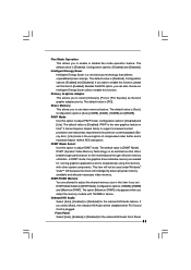
...- 1 x Floppy connector - 1 x Print port header - CPU Temperature Sensing - CPU/Chassis/Power Fan Tachometer - Voltage Monitoring: +12V, +5V, +3.3V, Vcore - ASRock OC Tuner (see CAUTION 8) - 8Mb AMI BIOS - CPU Quiet Fan - Microsoft® Windows® 7 / 7 64-bit / VistaTM / VistaTM 64-bit / XP... / XP 64-bit compliant 7 Front panel audio connector - 2 x USB 2.0 headers (support 4 USB 2.0 ports) (see CAUTION 9) - Intelligent Energy Saver (see CAUTION 12) - Hybrid Booster: -...
...- 1 x Floppy connector - 1 x Print port header - CPU Temperature Sensing - CPU/Chassis/Power Fan Tachometer - Voltage Monitoring: +12V, +5V, +3.3V, Vcore - ASRock OC Tuner (see CAUTION 8) - 8Mb AMI BIOS - CPU Quiet Fan - Microsoft® Windows® 7 / 7 64-bit / VistaTM / VistaTM 64-bit / XP... / XP 64-bit compliant 7 Front panel audio connector - 2 x USB 2.0 headers (support 4 USB 2.0 ports) (see CAUTION 9) - Intelligent Energy Saver (see CAUTION 12) - Hybrid Booster: -...
User Manual
Page 11
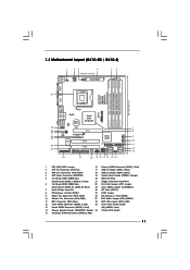
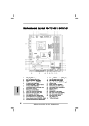
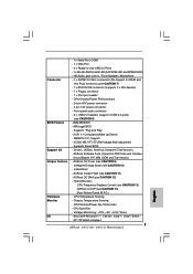
...17 USB 2.0 Header (USB6_7, Blue) 3 CPU Fan Connector (CPU_FAN1) 18 USB 2.0 Header (USB4_5, Blue) 4 ATX Power Connector (ATXPWR1) 19 System Panel Header (PANEL1, Orange) 5 2 x 240-pin DDR2 DIMM Slots 20 BIOS SPI Chip (Dual Channel: DDRII_1, DDRII_2; Blue) 23 Clear CMOS Jumper (CLRCMOS1...EUP Audio Jumper (EUP_AUDIO1) 11 IDE1 Connector (IDE1, Blue) 28 EUP LAN Jumper (EUP_LAN1) 12 Third SATAII Connector (SATAII_3; 1.3 Motherboard Layout (G41C-GS / G41C-S) 1 23 4 19.8cm (7.8 in) 1 PS2_USB_PWR1 ATX12V2 CPU_FAN1 56 PS2 Mouse PS2 Keyboard COM1 24.4cm (9.6 in) DDR3_B1 (64 bit, ...
...17 USB 2.0 Header (USB6_7, Blue) 3 CPU Fan Connector (CPU_FAN1) 18 USB 2.0 Header (USB4_5, Blue) 4 ATX Power Connector (ATXPWR1) 19 System Panel Header (PANEL1, Orange) 5 2 x 240-pin DDR2 DIMM Slots 20 BIOS SPI Chip (Dual Channel: DDRII_1, DDRII_2; Blue) 23 Clear CMOS Jumper (CLRCMOS1...EUP Audio Jumper (EUP_AUDIO1) 11 IDE1 Connector (IDE1, Blue) 28 EUP LAN Jumper (EUP_LAN1) 12 Third SATAII Connector (SATAII_3; 1.3 Motherboard Layout (G41C-GS / G41C-S) 1 23 4 19.8cm (7.8 in) 1 PS2_USB_PWR1 ATX12V2 CPU_FAN1 56 PS2 Mouse PS2 Keyboard COM1 24.4cm (9.6 in) DDR3_B1 (64 bit, ...

User Manual
Page 12
... click "Advanced Options" on the left side on your computer, you need to connect a front panel audio cable to save your change . Click "Power" to the front panel audio header. If you are allowed to save your change . 1.4 I/O Panel (G41C-GS) 1 2 3 4 5 10 9 8 7 6 1 PS/2 Mouse Port (Green) * 2 RJ-45 Port 3 Line In (Light Blue) 4 Line Out...
... click "Advanced Options" on the left side on your computer, you need to connect a front panel audio cable to save your change . Click "Power" to the front panel audio header. If you are allowed to save your change . 1.4 I/O Panel (G41C-GS) 1 2 3 4 5 10 9 8 7 6 1 PS/2 Mouse Port (Green) * 2 RJ-45 Port 3 Line In (Light Blue) 4 Line Out...

User Manual
Page 13
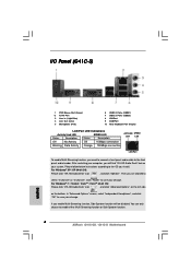
... cable to enable either Multi-Streaming function or Side Speaker function. 13 You can only choose to the front panel audio header. 1.4 I/O Panel (G41C-S) 1 2 3 4 5 10 9 8 7 6 1 PS/2 Mouse Port (Green) * 2 RJ-45 Port 3 Line In (Light Blue) 4 Line Out (Lime) 5 Microphone (Pink) 6 USB 2.0 Ports (USB01) 7 USB 2.0 Ports (USB23) 8 VGA Port 9 ...
... cable to enable either Multi-Streaming function or Side Speaker function. 13 You can only choose to the front panel audio header. 1.4 I/O Panel (G41C-S) 1 2 3 4 5 10 9 8 7 6 1 PS/2 Mouse Port (Green) * 2 RJ-45 Port 3 Line In (Light Blue) 4 Line Out (Lime) 5 Microphone (Pink) 6 USB 2.0 Ports (USB01) 7 USB 2.0 Ports (USB23) 8 VGA Port 9 ...
User Manual
Page 23
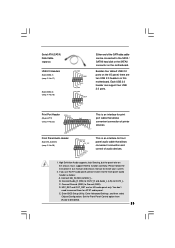
...this motherboard. Connect Mic_IN (MIC) to install your system. 2. Connect Ground (GND) to OUT2_L. High Definition Audio supports Jack Sensing, but the panel wire on the motherboard. Serial ATA (SATA) Data Cable (Optional) Either end of the SATA data cable can support two USB 2.0 ports. ...can be connected to the SATA / SATAII hard disk or the SATAII connector on the chassis must support HDA to connect them for front panel audio cable that allows convenient connection of printer devices. Connect Audio_R (RIN) to OUT2_R and Audio_L (LIN) to Ground (GND). C....
...this motherboard. Connect Mic_IN (MIC) to install your system. 2. Connect Ground (GND) to OUT2_L. High Definition Audio supports Jack Sensing, but the panel wire on the motherboard. Serial ATA (SATA) Data Cable (Optional) Either end of the SATA data cable can support two USB 2.0 ports. ...can be connected to the SATA / SATAII hard disk or the SATAII connector on the chassis must support HDA to connect them for front panel audio cable that allows convenient connection of printer devices. Connect Audio_R (RIN) to OUT2_R and Audio_L (LIN) to Ground (GND). C....
User Manual
Page 24
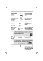
System Panel Header (9-pin PANEL1) (see p.11 No. 19) Chassis Speaker Header (4-pin SPEAKER 1) (see p.11 No. 9) GND +12V PWR_FAN_SPEED Please connect the fan cables to the ... +12V CHA_FAN_SPEED (3-pin PWR_FAN1) (see p.11 No. 14) PLED+ PLEDPWRBTN# GND 1 DUMMY RESET# GND HDLEDHDLED+ 1 SPEAKER DUMMY DUMMY +5V This header accommodates several system front panel functions. Though this header. Pin 1-3 Connected 3-Pin Fan Installation ATX Power Connector 24 (24-pin ATXPWR1) (see p.11 No. 4) 12 Please connect an ATX power...
System Panel Header (9-pin PANEL1) (see p.11 No. 19) Chassis Speaker Header (4-pin SPEAKER 1) (see p.11 No. 9) GND +12V PWR_FAN_SPEED Please connect the fan cables to the ... +12V CHA_FAN_SPEED (3-pin PWR_FAN1) (see p.11 No. 14) PLED+ PLEDPWRBTN# GND 1 DUMMY RESET# GND HDLEDHDLED+ 1 SPEAKER DUMMY DUMMY +5V This header accommodates several system front panel functions. Though this header. Pin 1-3 Connected 3-Pin Fan Installation ATX Power Connector 24 (24-pin ATXPWR1) (see p.11 No. 4) 12 Please connect an ATX power...
User Manual
Page 37
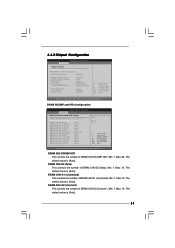
... Primary Graphics Adapter Shared Memory PAVP Mode DVMT Mode Select DVMT/FIXED Memory [Disabled] [PCI] [Auto] [Disabled] [DVMT Mode] [Maximum DVMT] Onboard HD Audio Front Panel OnBoard Lan [Auto] [Enabled] [Enabled] +F1 F9 F10 ESC Select Screen Select Item Change Option General Help Load Defaults Save and Exit Exit v02.54...
... Primary Graphics Adapter Shared Memory PAVP Mode DVMT Mode Select DVMT/FIXED Memory [Disabled] [PCI] [Auto] [Disabled] [DVMT Mode] [Maximum DVMT] Onboard HD Audio Front Panel OnBoard Lan [Auto] [Enabled] [Enabled] +F1 F9 F10 ESC Select Screen Select Item Change Option General Help Load Defaults Save and Exit Exit v02.54...
User Manual
Page 41
...: [128MB], [256MB] and [Maximum DVMT]. Onboard HD Audio Select [Auto], [Enabled] or [Disabled] for the onboard HD Audio Front Panel. 41 If you adopt the memory module with other system components. Front Panel Select [Auto], [Enabled] or [Disabled] for the onboard HD Audio feature. The default value is [Enabled]. Primary Graphics Adapter...
...: [128MB], [256MB] and [Maximum DVMT]. Onboard HD Audio Select [Auto], [Enabled] or [Disabled] for the onboard HD Audio Front Panel. 41 If you adopt the memory module with other system components. Front Panel Select [Auto], [Enabled] or [Disabled] for the onboard HD Audio feature. The default value is [Enabled]. Primary Graphics Adapter...
Quick Installation Guide
Page 2
... (ATX12V2) 17 USB 2.0 Header (USB6_7, Blue) 3 CPU Fan Connector (CPU_FAN1) 18 USB 2.0 Header (USB4_5, Blue) 4 ATX Power Connector (ATXPWR1) 19 System Panel Header (PANEL1, Orange) 5 2 x 240-pin DDR2 DIMM Slots 20 BIOS SPI Chip (Dual Channel: DDRII_1, DDRII_2; Blue) 23 Clear CMOS Jumper (CLRCMOS1) 7 ...Floppy Connector (FLOPPY1) 6 2 x 240-pin DDR3 DIMM Slots 22 Print Port Header (LPT1, Purple) (Dual Channel: DDR3_A1, DDR3_B1; Red) 2 ASRock G41C-GS / G41C-S Motherboard Motherboard Layout (G41C-GS / G41C-S) English 1 PS2_USB_PWR1 Jumper 16 Primary SATAII Connector (SATAII_1;
... (ATX12V2) 17 USB 2.0 Header (USB6_7, Blue) 3 CPU Fan Connector (CPU_FAN1) 18 USB 2.0 Header (USB4_5, Blue) 4 ATX Power Connector (ATXPWR1) 19 System Panel Header (PANEL1, Orange) 5 2 x 240-pin DDR2 DIMM Slots 20 BIOS SPI Chip (Dual Channel: DDRII_1, DDRII_2; Blue) 23 Clear CMOS Jumper (CLRCMOS1) 7 ...Floppy Connector (FLOPPY1) 6 2 x 240-pin DDR3 DIMM Slots 22 Print Port Header (LPT1, Purple) (Dual Channel: DDR3_A1, DDR3_B1; Red) 2 ASRock G41C-GS / G41C-S Motherboard Motherboard Layout (G41C-GS / G41C-S) English 1 PS2_USB_PWR1 Jumper 16 Primary SATAII Connector (SATAII_1;

Quick Installation Guide
Page 3
... on your change . After restarting your computer, you enable Multi-Streaming function, Side Speaker function will find "VIA HD Audio Deck" tool on the bottom. I/O Panel (G41C-GS) 1 PS/2 Mouse Port (Green) * 2 RJ-45 Port 3 Line In (Light Blue) 4 Line Out (Lime) 5 Microphone (Pink) 6 USB 2.0 ...LED LED LAN Port To enable Multi-Streaming function, you need to connect a front panel audio cable to enable either Multi-Streaming function or Side Speaker function. 3 ASRock G41C-GS / G41C-S Motherboard English Please follow below instructions according to save your change . Click "Power...
... on your change . After restarting your computer, you enable Multi-Streaming function, Side Speaker function will find "VIA HD Audio Deck" tool on the bottom. I/O Panel (G41C-GS) 1 PS/2 Mouse Port (Green) * 2 RJ-45 Port 3 Line In (Light Blue) 4 Line Out (Lime) 5 Microphone (Pink) 6 USB 2.0 ...LED LED LAN Port To enable Multi-Streaming function, you need to connect a front panel audio cable to enable either Multi-Streaming function or Side Speaker function. 3 ASRock G41C-GS / G41C-S Motherboard English Please follow below instructions according to save your change . Click "Power...
Quick Installation Guide
Page 4
... Click "Power" to save your computer, you will be disabled. Then you need to connect a front panel audio cable to the front panel audio header. For Windows® XP / XP 64-bit OS: Please click "VIA HD Audio Deck"... icon , and click "Speaker". I/O Panel (G41C-S) 1 PS/2 Mouse Port (Green) * 2 RJ-45 Port 3 Line In (Light Blue) 4 Line Out (Lime) 5 Microphone (Pink) 6... can only choose to enable either Multi-Streaming function or Side Speaker function. 4 ASRock G41C-GS / G41C-S Motherboard English
... Click "Power" to save your computer, you will be disabled. Then you need to connect a front panel audio cable to the front panel audio header. For Windows® XP / XP 64-bit OS: Please click "VIA HD Audio Deck"... icon , and click "Speaker". I/O Panel (G41C-S) 1 PS/2 Mouse Port (Green) * 2 RJ-45 Port 3 Line In (Light Blue) 4 Line Out (Lime) 5 Microphone (Pink) 6... can only choose to enable either Multi-Streaming function or Side Speaker function. 4 ASRock G41C-GS / G41C-S Motherboard English
Quick Installation Guide
Page 5
... occur, the updated version will be found in the user manual presented in , 24.4 cm x 19.8 cm) ASRock G41C-GS / G41C-S Quick Installation Guide ASRock G41C-GS / G41C-S Support CD Two Serial ATA (SATA) Data Cables (Optional) One I/O Panel Shield English 5 ASRock G41C-GS / G41C-S Motherboard Because the motherboard specifications and the BIOS software might be updated, the content of this manual will...
... occur, the updated version will be found in the user manual presented in , 24.4 cm x 19.8 cm) ASRock G41C-GS / G41C-S Quick Installation Guide ASRock G41C-GS / G41C-S Support CD Two Serial ATA (SATA) Data Cables (Optional) One I/O Panel Shield English 5 ASRock G41C-GS / G41C-S Motherboard Because the motherboard specifications and the BIOS software might be updated, the content of this manual will...
Quick Installation Guide
Page 6
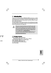
... x1 LAN 8103EL / 8102EL, speed 10/100 Mb/s - Supports FSB1333/1066/800/533 MHz - Northbridge: Intel® G41 - Max. Pixel Shader 4.0, DirectX 10 - G41C-GS: Realtek PCIE x1 Gigabit LAN RTL8111DL, speed 10/100/1000 Mb/s - Supports EM64T CPU - capacity of system memory: 8GB (see CAUTION 3) - 2 x DDR3 DIMM ...4) - Micro ATX Form Factor: 9.6-in x 7.8-in, 24.4 cm x 19.8 cm - Max. 1.2 Specifications Platform CPU Chipset Memory Expansion Slot Graphics Audio LAN Rear Panel I /O Panel - 1 x PS/2 Mouse Port - 1 x PS/2 Keyboard Port 6 ASRock G41C-GS / G41C-S Motherboard English
... x1 LAN 8103EL / 8102EL, speed 10/100 Mb/s - Supports FSB1333/1066/800/533 MHz - Northbridge: Intel® G41 - Max. Pixel Shader 4.0, DirectX 10 - G41C-GS: Realtek PCIE x1 Gigabit LAN RTL8111DL, speed 10/100/1000 Mb/s - Supports EM64T CPU - capacity of system memory: 8GB (see CAUTION 3) - 2 x DDR3 DIMM ...4) - Micro ATX Form Factor: 9.6-in x 7.8-in, 24.4 cm x 19.8 cm - Max. 1.2 Specifications Platform CPU Chipset Memory Expansion Slot Graphics Audio LAN Rear Panel I /O Panel - 1 x PS/2 Mouse Port - 1 x PS/2 Keyboard Port 6 ASRock G41C-GS / G41C-S Motherboard English
Quick Installation Guide
Page 7
...174; Windows® 7 / 7 64-bit / VistaTM / VistaTM 64-bit / XP / XP 64-bit compliant 7 ASRock G41C-GS / G41C-S Motherboard ACPI 1.1 Compliance Wake Up Events - ASRock Instant Flash (see CAUTION 9) - CPU/Chassis/Power Fan Tachometer - Chassis Temperature Sensing English - CPU Quiet Fan - CPU ...- 4 pin 12V power connector - Front panel audio connector - 2 x USB 2.0 headers (support 4 USB 2.0 ports) (see CAUTION 10) - Supports Smart BIOS Support CD - Drivers, Utilities, AntiVirus Software (Trial Version), ASRock Software Suite (CyberLink DVD Suite and Creative Sound...
...174; Windows® 7 / 7 64-bit / VistaTM / VistaTM 64-bit / XP / XP 64-bit compliant 7 ASRock G41C-GS / G41C-S Motherboard ACPI 1.1 Compliance Wake Up Events - ASRock Instant Flash (see CAUTION 9) - CPU/Chassis/Power Fan Tachometer - Chassis Temperature Sensing English - CPU Quiet Fan - CPU ...- 4 pin 12V power connector - Front panel audio connector - 2 x USB 2.0 headers (support 4 USB 2.0 ports) (see CAUTION 10) - Supports Smart BIOS Support CD - Drivers, Utilities, AntiVirus Software (Trial Version), ASRock Software Suite (CyberLink DVD Suite and Creative Sound...
Quick Installation Guide
Page 19
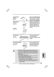
... on this motherboard. Connect Audio_R (RIN) to OUT2_R and Audio_L (LIN) to [Enabled]. 19 ASRock G41C-GS / G41C-S Motherboard English Set the Front Panel Control option from [Auto] to OUT2_L. Print Port Header (25-pin LPT1) (see p.2 No. 22) Front Panel Audio Header (9-pin HD_AUDIO1) (see p.2 No. 18) Either end of the SATA data cable can...
... on this motherboard. Connect Audio_R (RIN) to OUT2_R and Audio_L (LIN) to [Enabled]. 19 ASRock G41C-GS / G41C-S Motherboard English Set the Front Panel Control option from [Auto] to OUT2_L. Print Port Header (25-pin LPT1) (see p.2 No. 22) Front Panel Audio Header (9-pin HD_AUDIO1) (see p.2 No. 18) Either end of the SATA data cable can...

Quick Installation Guide
Page 20
System Panel Header (9-pin PANEL1) (see p.2 No. 3) 1 2 3 4 Please connect a CPU fan cable to this connector and match the black ...Please connect an ATX power 13 supply to Pin 1-3. CPU Fan Connector (4-pin CPU_FAN1) (see p.2 No. 19) This header accommodates several system front panel functions. Pin 1-3 Connected 3-Pin Fan Installation ATX Power Connector 24 (24-pin ATXPWR1) (see p.2 No. 2) ATX 12V plug to this connector so... CHA_FAN1) (see p.2 No. 10) (3-pin PWR_FAN1) (see p.2 No. 14) Please connect the chassis speaker to power up. 20 ASRock G41C-GS / G41C-S Motherboard English
System Panel Header (9-pin PANEL1) (see p.2 No. 3) 1 2 3 4 Please connect a CPU fan cable to this connector and match the black ...Please connect an ATX power 13 supply to Pin 1-3. CPU Fan Connector (4-pin CPU_FAN1) (see p.2 No. 19) This header accommodates several system front panel functions. Pin 1-3 Connected 3-Pin Fan Installation ATX Power Connector 24 (24-pin ATXPWR1) (see p.2 No. 2) ATX 12V plug to this connector so... CHA_FAN1) (see p.2 No. 10) (3-pin PWR_FAN1) (see p.2 No. 14) Please connect the chassis speaker to power up. 20 ASRock G41C-GS / G41C-S Motherboard English

