RAID Installation Guide
Page 1
... RAID 3 2.2 RAID Configuration Precautions 6 2.3 Installing Windows® 8 / 8 64-bit / 7 / 7 64-bit With RAID Functions 7 2.4 Setting the BIOS RAID Items 8 2.5 Configuring a RAID array 8 2.5.1 Configuring a RAID array Using UEFI Setup Utility....... 8 2.5.2 Configuring a RAID array Using Intel RAID BIOS....... 13 3. Guide to SATA Hard Disks Installation 2 1.1 Serial ATA (SATA) Hard Disks Installation 2 2. Installing Windows®...
... RAID 3 2.2 RAID Configuration Precautions 6 2.3 Installing Windows® 8 / 8 64-bit / 7 / 7 64-bit With RAID Functions 7 2.4 Setting the BIOS RAID Items 8 2.5 Configuring a RAID array 8 2.5.1 Configuring a RAID array Using UEFI Setup Utility....... 8 2.5.2 Configuring a RAID array Using Intel RAID BIOS....... 13 3. Guide to SATA Hard Disks Installation 2 1.1 Serial ATA (SATA) Hard Disks Installation 2 2. Installing Windows®...
RAID Installation Guide
Page 8
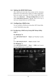
...please set "Fast Boot" to [Ultra Fast]. Press key to save your change before you exit BIOS setup. 2.5 Configuring a RAID array You can configure a RAID array using either UEFI Setup Utility or Intel® RAID BIOS setup utility. 2.5.1 Configuring a RAID array Using UEFI Setup Utility STEP 1: For Windows® 8: ...Go to UEFI SETUP UTILITY Boot to set the necessary RAID items in the BIOS before setting your system, and press key to disable "CSM". For Windows® 7: Go to UEFI SETUP UTILITY Boot CSM to set the option SATA...
...please set "Fast Boot" to [Ultra Fast]. Press key to save your change before you exit BIOS setup. 2.5 Configuring a RAID array You can configure a RAID array using either UEFI Setup Utility or Intel® RAID BIOS setup utility. 2.5.1 Configuring a RAID array Using UEFI Setup Utility STEP 1: For Windows® 8: ...Go to UEFI SETUP UTILITY Boot to set the necessary RAID items in the BIOS before setting your system, and press key to disable "CSM". For Windows® 7: Go to UEFI SETUP UTILITY Boot CSM to set the option SATA...
RAID Installation Guide
Page 13
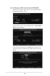
Press . Then, the Intel RAID Utility - Volume0 13 2.5.2 Configuring a RAID array Using Intel RAID BIOS Reboot your RAID volume then press . Wait until you see the RAID software prompting you to press . Create RAID Volume window appears. In the Create Volume Menu, under Name item, please key-in a unique name with 1-16 letters for your computer.
Press . Then, the Intel RAID Utility - Volume0 13 2.5.2 Configuring a RAID array Using Intel RAID BIOS Reboot your RAID volume then press . Wait until you see the RAID software prompting you to press . Create RAID Volume window appears. In the Create Volume Menu, under Name item, please key-in a unique name with 1-16 letters for your computer.

RAID Installation Guide
Page 16
Please note that you want to create an extra RAID partition, please use the RAID utility under BIOS RAID environment. If you set up. Press to delete a RAID volume, please select the option Delete RAID Volume, press , and then follow the instructions on the screen. 16 If you install OS. After the completion, you will see the detailed information about the RAID that you are only allowed to create one RAID partition at a time under Windows environment to configure RAID functions after you want to complete the setup of RAID.
Please note that you want to create an extra RAID partition, please use the RAID utility under BIOS RAID environment. If you set up. Press to delete a RAID volume, please select the option Delete RAID Volume, press , and then follow the instructions on the screen. 16 If you install OS. After the completion, you will see the detailed information about the RAID that you are only allowed to create one RAID partition at a time under Windows environment to configure RAID functions after you want to complete the setup of RAID.
RAID Installation Guide
Page 17
3. Installing Windows® on a HDD under 2TB in RAID mode After the UEFI and RAID BIOS setup you may start installing Windows® 8 / 8 64-bit / 7 / 7 64-bit OS as usual. 17
3. Installing Windows® on a HDD under 2TB in RAID mode After the UEFI and RAID BIOS setup you may start installing Windows® 8 / 8 64-bit / 7 / 7 64-bit OS as usual. 17
RAID Installation Guide
Page 18
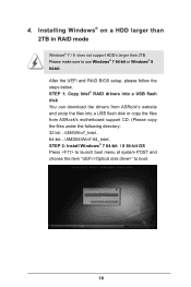
After the UEFI and RAID BIOS setup, please follow the steps below. Please make sure to boot. 18 STEP 1: Copy Intel® RAID drivers into a USB flash disk You can download the drivers from ASRock's website and unzip the files into a USB flash disk or copy the files from ASRock's motherboard support CD. (Please...
After the UEFI and RAID BIOS setup, please follow the steps below. Please make sure to boot. 18 STEP 1: Copy Intel® RAID drivers into a USB flash disk You can download the drivers from ASRock's website and unzip the files into a USB flash disk or copy the files from ASRock's motherboard support CD. (Please...

Intel Rapid Storage Guide
Page 12
...(F6 install method) In order to install an operating system onto a RAID volume, the RAID option must be enabled in the system BIOS. 1. Press Enter to enter the BIOS Setup program after the Power-On-Self-Test (POST) memory test begins. 2. When finished press Enter. 12 Click F2 or Delete ...of hard drives by using the up or down arrow keys to save the BIOS settings and exit the BIOS Setup program. Enable RAID in System BIOS Use the instructions included with your motherboard to enable RAID in the system BIOS, a RAID volume must be created, and the F6 installation method must ...
...(F6 install method) In order to install an operating system onto a RAID volume, the RAID option must be enabled in the system BIOS. 1. Press Enter to enter the BIOS Setup program after the Power-On-Self-Test (POST) memory test begins. 2. When finished press Enter. 12 Click F2 or Delete ...of hard drives by using the up or down arrow keys to save the BIOS settings and exit the BIOS Setup program. Enable RAID in System BIOS Use the instructions included with your motherboard to enable RAID in the system BIOS, a RAID volume must be created, and the F6 installation method must ...
User Manual
Page 8
... Card • 1 x Front USB 3.0 Panel with robust design conforming to ASRock's commitment to change without further notice. Fatal1ty Z87 Professional Series Chapter 1 Introduction Thank you are using. Chapter 3 contains the operation guide of the BIOS setup. Because the motherboard specifications and the BIOS software might be updated, the content of the motherboard and step-by-step...
... Card • 1 x Front USB 3.0 Panel with robust design conforming to ASRock's commitment to change without further notice. Fatal1ty Z87 Professional Series Chapter 1 Introduction Thank you are using. Chapter 3 contains the operation guide of the BIOS setup. Because the motherboard specifications and the BIOS software might be updated, the content of the motherboard and step-by-step...
User Manual
Page 12
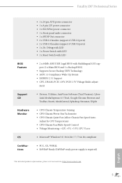
Fatal1ty Z87 Professional Series BIOS Feature Support CD Hardware Monitor OS Certifications • 1 x 24 pin ATX power connector • 1 x 8 pin 12V power connector • 1 x SLI/XFire power connector • 1 x ... • FCC, CE, WHQL • ErP/EuP Ready (ErP/EuP ready power supply is required) * For detailed product information, please visit our website: http://www.asrock.com 5 English ment • Drivers, Utilities, AntiVirus Software (Trial Version), CyberLink MediaEspresso 6.5 Trial, Google Chrome Browser and Toolbar, Start8, MeshCentral, Splashtop Streamer, XSplit •...
Fatal1ty Z87 Professional Series BIOS Feature Support CD Hardware Monitor OS Certifications • 1 x 24 pin ATX power connector • 1 x 8 pin 12V power connector • 1 x SLI/XFire power connector • 1 x ... • FCC, CE, WHQL • ErP/EuP Ready (ErP/EuP ready power supply is required) * For detailed product information, please visit our website: http://www.asrock.com 5 English ment • Drivers, Utilities, AntiVirus Software (Trial Version), CyberLink MediaEspresso 6.5 Trial, Google Chrome Browser and Toolbar, Start8, MeshCentral, Splashtop Streamer, XSplit •...

User Manual
Page 13
... your system's stability, or even cause damage to utilize the memory that there is a certain risk involved with overclocking, including adjusting the setting in the BIOS, applying Untied Overclocking Technology, or using thirdparty overclocking tools. Please realize that Windows® cannot use. 6 English We are not responsible for system usage under.... Overclocking may be done at your system. It should be less than 4GB for the reservation for possible damage caused by overclocking. You can use ASRock XFast RAM to the components and devices of your own risk and expense.
... your system's stability, or even cause damage to utilize the memory that there is a certain risk involved with overclocking, including adjusting the setting in the BIOS, applying Untied Overclocking Technology, or using thirdparty overclocking tools. Please realize that Windows® cannot use. 6 English We are not responsible for system usage under.... Overclocking may be done at your system. It should be less than 4GB for the reservation for possible damage caused by overclocking. You can use ASRock XFast RAM to the components and devices of your own risk and expense.

User Manual
Page 14
Fatal1ty Z87 Professional Series 1.3 Unique Features ASRock F-Stream F-Stream is a BIOS flash utility embedded in a few clicks without preparing an additional floppy diskette or other complicated flash utility. Please be noted that the USB flash drive or hard drive must use FAT32/16/12 file system. ASRock APP Charger allows ...), hibernation mode (S4) or power off (S5). Lower Latency in games. Just save the new BIOS file to your USB storage and launch this tool by installing the ASRock APP Charger makes your PC enters into Standby mode (S1), Suspend to the list. Traffic Shaping: ...
Fatal1ty Z87 Professional Series 1.3 Unique Features ASRock F-Stream F-Stream is a BIOS flash utility embedded in a few clicks without preparing an additional floppy diskette or other complicated flash utility. Please be noted that the USB flash drive or hard drive must use FAT32/16/12 file system. ASRock APP Charger allows ...), hibernation mode (S4) or power off (S5). Lower Latency in games. Just save the new BIOS file to your USB storage and launch this tool by installing the ASRock APP Charger makes your PC enters into Standby mode (S1), Suspend to the list. Traffic Shaping: ...
User Manual
Page 15
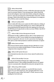
... RAID Installer can start installing the OS in the root directory of your USB disk. ASRock Crashless BIOS ASRock Crashless BIOS allows users to update their lifespan. ASRock Internet Flash ASRock Internet Flash downloads and updates the latest UEFI firmware version from our servers for you to copy...placed in RAID mode. 8 English Only USB 2.0 ports support this feature. ASRock XFast RAM ASRock XFast RAM is that BIOS files need to be used under Windows® 32-bit operating systems. ASRock XFast RAM shortens the loading time of previously visited websites, making web surfing ...
... RAID Installer can start installing the OS in the root directory of your USB disk. ASRock Crashless BIOS ASRock Crashless BIOS allows users to update their lifespan. ASRock Internet Flash ASRock Internet Flash downloads and updates the latest UEFI firmware version from our servers for you to copy...placed in RAID mode. 8 English Only USB 2.0 ports support this feature. ASRock XFast RAM ASRock XFast RAM is that BIOS files need to be used under Windows® 32-bit operating systems. ASRock XFast RAM shortens the loading time of previously visited websites, making web surfing ...

User Manual
Page 16
... switch off the Power and Keyboard LEDs when the system enters into lethal weapons. By enabling Good Night LED in the BIOS, the Power/HDD LEDs will be switched off , monitor and take control of system configuration tools, cool sound effects and...when turning on . The lightning boot up experience. ASRock Good Night LED ASRock Good Night LED technology offers you restart. No more amusment. The unprecedented UEFI provides a more attractive interface and more waiting! Fatal1ty Z87 Professional Series ASRock Interactive UEFI ASRock Interactive UEFI is a blend of it takes less ...
... switch off the Power and Keyboard LEDs when the system enters into lethal weapons. By enabling Good Night LED in the BIOS, the Power/HDD LEDs will be switched off , monitor and take control of system configuration tools, cool sound effects and...when turning on . The lightning boot up experience. ASRock Good Night LED ASRock Good Night LED technology offers you restart. No more amusment. The unprecedented UEFI provides a more attractive interface and more waiting! Fatal1ty Z87 Professional Series ASRock Interactive UEFI ASRock Interactive UEFI is a blend of it takes less ...

User Manual
Page 18
1.4 Motherboard Layout Fatal1ty Z87 Professional Series USB 2.0 T: USB0 B: USB1 PS2 Keyboard Clr CMOS PWR_FAN1 ATX12V1 DP_1 HDMI1 HDMI_IN1 CPU_FAN1 CPU_FAN2 DDR3_A1 (64 bit, 240-pin module...PCIE2 SATA3_0_1 Sound CORE3D Super I/O PCI1 Z87 PROFESSIONAL PCIE3 RoHS PCI2 HD_AUDIO1 IR1 SPDIF1_OUT1 1 1 1 SLI/XFIRE_PWR1 PCIE4 COM1 1 USB3_6_7 1 USB6_7 1 USB4_5 1 SATA3_2_3 Intel Z87 SATA3_4_5 Dr. Debug CLRCMOS1 1 1 BIOS_SEL1 PLED1 1 SPEAKER1 1 PLED PWRBTN CHA_FAN1 1 HDLED RESET PANEL1 BIOS_B_LED 64Mb BIOS 64Mb BIOS BIOS_B BIOS_A BIOS_A_LED Reset Power English 11
1.4 Motherboard Layout Fatal1ty Z87 Professional Series USB 2.0 T: USB0 B: USB1 PS2 Keyboard Clr CMOS PWR_FAN1 ATX12V1 DP_1 HDMI1 HDMI_IN1 CPU_FAN1 CPU_FAN2 DDR3_A1 (64 bit, 240-pin module...PCIE2 SATA3_0_1 Sound CORE3D Super I/O PCI1 Z87 PROFESSIONAL PCIE3 RoHS PCI2 HD_AUDIO1 IR1 SPDIF1_OUT1 1 1 1 SLI/XFIRE_PWR1 PCIE4 COM1 1 USB3_6_7 1 USB6_7 1 USB4_5 1 SATA3_2_3 Intel Z87 SATA3_4_5 Dr. Debug CLRCMOS1 1 1 BIOS_SEL1 PLED1 1 SPEAKER1 1 PLED PWRBTN CHA_FAN1 1 HDLED RESET PANEL1 BIOS_B_LED 64Mb BIOS 64Mb BIOS BIOS_B BIOS_A BIOS_A_LED Reset Power English 11

User Manual
Page 19
...) 15 Reset Switch (RSTBTN1) 16 Chassis Speaker Header (SPEAKER1) 17 System Panel Header (PANEL1) 18 Power LED Header (PLED1) 19 Chassis Fan Connector (CHA_FAN1) 20 BIOS Selection Jumper (BIOS_SEL1) 21 Clear CMOS Jumper (CLRCMOS1) 22 USB 2.0 Header (USB4_5) 23 USB 2.0 Header (USB6_7) 24 USB 3.0 Header (USB3_6_7) 25 COM Port Header (COM1...
...) 15 Reset Switch (RSTBTN1) 16 Chassis Speaker Header (SPEAKER1) 17 System Panel Header (PANEL1) 18 Power LED Header (PLED1) 19 Chassis Fan Connector (CHA_FAN1) 20 BIOS Selection Jumper (BIOS_SEL1) 21 Clear CMOS Jumper (CLRCMOS1) 22 USB 2.0 Header (USB4_5) 23 USB 2.0 Header (USB6_7) 24 USB 3.0 Header (USB3_6_7) 25 COM Port Header (COM1...

User Manual
Page 30
... you just finish updating the BIOS, you must boot up the system first, and then shut it down before you do not clear the CMOS right after you to clear the data in CMOS. When the jumper cap is placed on the pins, the jumper is removed. Fatal1ty Z87 Professional Series 2.5 Jumpers Setup The... be cleared only if the CMOS battery is "Short". Clear CMOS Jumper (CLRCMOS1) (see p.11, No. 21) Default Clear CMOS CLRCMOS1 allows you update the BIOS. To clear and reset the system parameters to short pin2 and pin3 on the pins, the jumper is "Open". The Clear CMOS Switch has the...
... you just finish updating the BIOS, you must boot up the system first, and then shut it down before you do not clear the CMOS right after you to clear the data in CMOS. When the jumper cap is placed on the pins, the jumper is removed. Fatal1ty Z87 Professional Series 2.5 Jumpers Setup The... be cleared only if the CMOS battery is "Short". Clear CMOS Jumper (CLRCMOS1) (see p.11, No. 21) Default Clear CMOS CLRCMOS1 allows you update the BIOS. To clear and reset the system parameters to short pin2 and pin3 on the pins, the jumper is "Open". The Clear CMOS Switch has the...

User Manual
Page 31
... that, short pin1 and pin2 again, then use a jumper cap to short pin2 and pin3, then the backup BIOS will take over on the main BIOS. Users may refer to the BIOS LED (BIOS_A_LED or BIOS_B_LED) to ensure normal system operation. For the sake of your system. English 24 However, ...if the main BIOS is corrupted or damaged, please use "Secure Backup UEFI" in BIOS setup utility to copy the BIOS file to the main BIOS to identify which enhances protection for the safety and stability of system safety, users ...
... that, short pin1 and pin2 again, then use a jumper cap to short pin2 and pin3, then the backup BIOS will take over on the main BIOS. Users may refer to the BIOS LED (BIOS_A_LED or BIOS_B_LED) to ensure normal system operation. For the sake of your system. English 24 However, ...if the main BIOS is corrupted or damaged, please use "Secure Backup UEFI" in BIOS setup utility to copy the BIOS file to the main BIOS to identify which enhances protection for the safety and stability of system safety, users ...
User Manual
Page 45
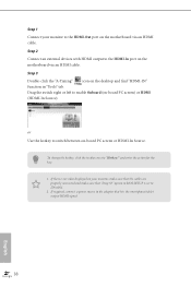
... enable Onboard (on the motherboard via an HDMI cable. To change the hotkey, click the textbox next to the adapter that "Deep S5" option in BIOS SETUP is no video displayed on the desktop and find "HDMI-IN" function in "Tools" tab. Step 2 Connect an external devices with HDMI output to...
... enable Onboard (on the motherboard via an HDMI cable. To change the hotkey, click the textbox next to the adapter that "Deep S5" option in BIOS SETUP is no video displayed on the desktop and find "HDMI-IN" function in "Tools" tab. Step 2 Connect an external devices with HDMI output to...

User Manual
Page 59
...Create. The system will discover the new device and install AHCI drivers automatically. 3.3.2 Setup Guide Configuring Rapid Start Step 1 Run ASRock Rapid Start utility from Start -> All Programs -> ASRock Utility. Step 2 If you have more than one hard drives in your system, you must select one, then choose the... according to AHCI. If there are SSD's installed into your system, it is recommended to save changes and exit. 5. Press F2 to enter BIOS, then go to Advanced ‐> Storage Configuration and change SATA Mode to your hidden partition and click on the SSD. 52 English Exit the...
...Create. The system will discover the new device and install AHCI drivers automatically. 3.3.2 Setup Guide Configuring Rapid Start Step 1 Run ASRock Rapid Start utility from Start -> All Programs -> ASRock Utility. Step 2 If you have more than one hard drives in your system, you must select one, then choose the... according to AHCI. If there are SSD's installed into your system, it is recommended to save changes and exit. 5. Press F2 to enter BIOS, then go to Advanced ‐> Storage Configuration and change SATA Mode to your hidden partition and click on the SSD. 52 English Exit the...

User Manual
Page 91
... run the UEFI SETUP UTILITY by pressing the reset button on the computer, otherwise, the Power-On-Self-Test (POST) will it make BIOS setup less difficult but also a lot more amusing. If you wish to configure your screen. 4.1.1 UEFI Menu Bar The top of system ... Because the UEFI software is a blend of the screen has a menu bar with its test routines. Chapter 4 UEFI SETUP UTILITY 4.1 Introduction ASRock Interactive UEFI is constantly being updated, the following UEFI setup screens and descriptions are for reference purpose only, and they may also restart by turning...
... run the UEFI SETUP UTILITY by pressing the reset button on the computer, otherwise, the Power-On-Self-Test (POST) will it make BIOS setup less difficult but also a lot more amusing. If you wish to configure your screen. 4.1.1 UEFI Menu Bar The top of system ... Because the UEFI software is a blend of the screen has a menu bar with its test routines. Chapter 4 UEFI SETUP UTILITY 4.1 Introduction ASRock Interactive UEFI is constantly being updated, the following UEFI setup screens and descriptions are for reference purpose only, and they may also restart by turning...


