
Intel Smart Response Installation Guide
Page 1
For the new version RST driver, please check our website for the latest information: http://www.asrock.com * Before you use RST function, you want to use Enhanced or Maximized Mode. 6. Once open RST GUI from either Start Menu or by step ... installing the OS to [RAID Mode]. For all required drivers, including RST storage driver version 10.5 or later. 2. Intel Smart Response Technology Installation Guide This motherboard supports Intel Smart Response Technology. UI setup instruction: 1. It is not necessary to use the full SSD as the Cache device, which HDD you wish...
For the new version RST driver, please check our website for the latest information: http://www.asrock.com * Before you use RST function, you want to use Enhanced or Maximized Mode. 6. Once open RST GUI from either Start Menu or by step ... installing the OS to [RAID Mode]. For all required drivers, including RST storage driver version 10.5 or later. 2. Intel Smart Response Technology Installation Guide This motherboard supports Intel Smart Response Technology. UI setup instruction: 1. It is not necessary to use the full SSD as the Cache device, which HDD you wish...
RAID Installation Guide
Page 2
You may install SATA hard disks on SATA ports. 2 Guide to the Intel southbridge chipset that your motherboard adopts. This section will guide you how to create RAID on this guide carefully according to SATA Hard Disks Installation 1.1 Serial ATA (SATA) Hard Disks Installation Intel chipset supports Serial ATA (SATA) hard disks with RAID functions, including RAID 0, RAID 1, RAID 5, RAID 10 and Intel Rapid Storage. Please read the RAID configurations in this motherboard for internal storage devices. 1.
You may install SATA hard disks on SATA ports. 2 Guide to the Intel southbridge chipset that your motherboard adopts. This section will guide you how to create RAID on this guide carefully according to SATA Hard Disks Installation 1.1 Serial ATA (SATA) Hard Disks Installation Intel chipset supports Serial ATA (SATA) hard disks with RAID functions, including RAID 0, RAID 1, RAID 5, RAID 10 and Intel Rapid Storage. Please read the RAID configurations in this motherboard for internal storage devices. 1.
RAID Installation Guide
Page 3
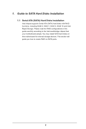
Guide to RAID Configurations 2.1 Introduction of RAID This motherboard adopts Intel southbridge chipset that optimizes two identical hard disk drives to read and write data in parallel, interleaved stacks. It will improve data access ...
Guide to RAID Configurations 2.1 Introduction of RAID This motherboard adopts Intel southbridge chipset that optimizes two identical hard disk drives to read and write data in parallel, interleaved stacks. It will improve data access ...
RAID Installation Guide
Page 18
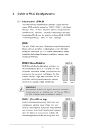
...; 8 64-bit. 4. STEP 1: Copy Intel® RAID drivers into a USB flash disk You can download the drivers from ASRock's website and unzip the files into a USB flash disk or copy the files from ASRock's motherboard support CD. (Please copy the files under the following directory: 32 bit: ..\i386\Win7_Intel.. 64-bit: ..\AMD64\Win7...
...; 8 64-bit. 4. STEP 1: Copy Intel® RAID drivers into a USB flash disk You can download the drivers from ASRock's website and unzip the files into a USB flash disk or copy the files from ASRock's motherboard support CD. (Please copy the files under the following directory: 32 bit: ..\i386\Win7_Intel.. 64-bit: ..\AMD64\Win7...
RAID Installation Guide
Page 20
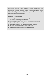
... may take a long time; >30 mins.) C. After installing Windows® 7 64-bit / 8 64-bit, install the hotfix kb2505454. (This may take about 5 minutes to install motherboard drivers and utilities. 20
... may take a long time; >30 mins.) C. After installing Windows® 7 64-bit / 8 64-bit, install the hotfix kb2505454. (This may take about 5 minutes to install motherboard drivers and utilities. 20

Intel Rapid Storage Guide
Page 12
... the Intel Rapid Storage Technology option ROM status screen appears during operating system setup. Enable RAID in System BIOS Use the instructions included with your motherboard to enter the BIOS Setup program after the Power-On-Self-Test (POST) memory test begins. 2. Click F2 or Delete to enable RAID in the...
... the Intel Rapid Storage Technology option ROM status screen appears during operating system setup. Enable RAID in System BIOS Use the instructions included with your motherboard to enter the BIOS Setup program after the Power-On-Self-Test (POST) memory test begins. 2. Click F2 or Delete to enable RAID in the...

User Manual
Page 2
Operation is subject to the following two conditions: (1) this device may not cause harmful interference, and (2) this motherboard contains Perchlorate, a toxic substance controlled in Perchlorate Best Management Practices (BMP) regulations passed by the purchaser for a particular purpose....this device must accept any means, except duplication of such damages arising from any defect or error in any form or by ASRock. Disclaimer: Specifications and information contained in this documentation are furnished for informational use only and subject to the implied warranties or ...
Operation is subject to the following two conditions: (1) this device may not cause harmful interference, and (2) this motherboard contains Perchlorate, a toxic substance controlled in Perchlorate Best Management Practices (BMP) regulations passed by the purchaser for a particular purpose....this device must accept any means, except duplication of such damages arising from any defect or error in any form or by ASRock. Disclaimer: Specifications and information contained in this documentation are furnished for informational use only and subject to the implied warranties or ...

User Manual
Page 5
Contents Chapter 1 Introduction 1 1.1 Package Contents 1 1.2 Specifications 2 1.3 Unique Features 7 1.4 Motherboard Layout 11 1.5 I/O Panel 13 Chapter 2 Installation 15 2.1 Installing the CPU 16 2.2 Installing the CPU Fan and Heatsink 19 2.3 Installing Memory Modules (DIMM) 20 2.4 Expansion Slots (...
Contents Chapter 1 Introduction 1 1.1 Package Contents 1 1.2 Specifications 2 1.3 Unique Features 7 1.4 Motherboard Layout 11 1.5 I/O Panel 13 Chapter 2 Installation 15 2.1 Installing the CPU 16 2.2 Installing the CPU Fan and Heatsink 19 2.3 Installing Memory Modules (DIMM) 20 2.4 Expansion Slots (...
User Manual
Page 8
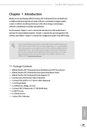
... visit our website for purchasing ASRock Fatal1ty Z87 Professional Series motherboard, a reliable motherboard produced under ASRock's consistently stringent quality control. ASRock website http://www.asrock.com. 1.1 Package Contents • ASRock Fatal1ty Z87 Professional Series Motherboard (ATX Form Factor) • ASRock Fatal1ty Z87 Professional Series Quick Installation Guide • ASRock Fatal1ty Z87 Professional Series Support CD • 8 x Serial ATA (SATA) Data Cables (Optional) • 2 x Serial ATA (SATA) 1 to 1 Power Cables (Optional) • 1 x I/O Panel...
... visit our website for purchasing ASRock Fatal1ty Z87 Professional Series motherboard, a reliable motherboard produced under ASRock's consistently stringent quality control. ASRock website http://www.asrock.com. 1.1 Package Contents • ASRock Fatal1ty Z87 Professional Series Motherboard (ATX Form Factor) • ASRock Fatal1ty Z87 Professional Series Quick Installation Guide • ASRock Fatal1ty Z87 Professional Series Support CD • 8 x Serial ATA (SATA) Data Cables (Optional) • 2 x Serial ATA (SATA) 1 to 1 Power Cables (Optional) • 1 x I/O Panel...
User Manual
Page 15
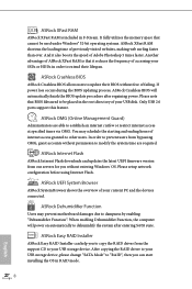
...BIOS without entering Windows® OS. If power loss occurs during the BIOS updating process, ASRock Crashless BIOS will power on automatically to other users. You may prevent motherboard damages due to your USB disk. When enabling Dehumidifier Function, the computer will automatically finish... the BIOS update procedure after entering S4/S5 state. ASRock XFast RAM ASRock XFast RAM is that it also boosts the...
...BIOS without entering Windows® OS. If power loss occurs during the BIOS updating process, ASRock Crashless BIOS will power on automatically to other users. You may prevent motherboard damages due to your USB disk. When enabling Dehumidifier Function, the computer will automatically finish... the BIOS update procedure after entering S4/S5 state. ASRock XFast RAM ASRock XFast RAM is that it also boosts the...

User Manual
Page 16
...off , monitor and take control of system configuration tools, cool sound effects and stunning visuals. The lightning boot up experience. ASRock Key Master What good is powered on the PC. Key Master enhances your mouse and keyboard with the onboard Intel LAN, ...it hard to access the UEFI setup. ASRock Home Cloud This motherboard supports remote wake with customizable macros, sniper modes, scroll speed, key repeat rates and repeat delay, turning your PC from a cold boot. Fatal1ty Z87 Professional Series ASRock Interactive UEFI ASRock Interactive UEFI is money, why waste precious...
...off , monitor and take control of system configuration tools, cool sound effects and stunning visuals. The lightning boot up experience. ASRock Key Master What good is powered on the PC. Key Master enhances your mouse and keyboard with the onboard Intel LAN, ...it hard to access the UEFI setup. ASRock Home Cloud This motherboard supports remote wake with customizable macros, sniper modes, scroll speed, key repeat rates and repeat delay, turning your PC from a cold boot. Fatal1ty Z87 Professional Series ASRock Interactive UEFI ASRock Interactive UEFI is money, why waste precious...

User Manual
Page 18
1.4 Motherboard Layout Fatal1ty Z87 Professional Series USB 2.0 T: USB0 B: USB1 PS2 Keyboard Clr CMOS PWR_FAN1 ATX12V1 DP_1 HDMI1 HDMI_IN1 CPU_FAN1 CPU_FAN2 DDR3_A1 (64 bit, 240-pin ...1 PCIE1 CHA_FAN3 CHA_FAN2 1 FATAL TY SATA3_A1_A2 SATA3_A3_A4 MINI_PCIE1 CMOS Battery PCIE2 SATA3_0_1 Sound CORE3D Super I/O PCI1 Z87 PROFESSIONAL PCIE3 RoHS PCI2 HD_AUDIO1 IR1 SPDIF1_OUT1 1 1 1 SLI/XFIRE_PWR1 PCIE4 COM1 1 USB3_6_7 1 USB6_7 1 USB4_5 1 SATA3_2_3 Intel Z87 SATA3_4_5 Dr. Debug CLRCMOS1 1 1 BIOS_SEL1 PLED1 1 SPEAKER1 1 PLED PWRBTN CHA_FAN1 1 HDLED RESET PANEL1 ...
1.4 Motherboard Layout Fatal1ty Z87 Professional Series USB 2.0 T: USB0 B: USB1 PS2 Keyboard Clr CMOS PWR_FAN1 ATX12V1 DP_1 HDMI1 HDMI_IN1 CPU_FAN1 CPU_FAN2 DDR3_A1 (64 bit, 240-pin ...1 PCIE1 CHA_FAN3 CHA_FAN2 1 FATAL TY SATA3_A1_A2 SATA3_A3_A4 MINI_PCIE1 CMOS Battery PCIE2 SATA3_0_1 Sound CORE3D Super I/O PCI1 Z87 PROFESSIONAL PCIE3 RoHS PCI2 HD_AUDIO1 IR1 SPDIF1_OUT1 1 1 1 SLI/XFIRE_PWR1 PCIE4 COM1 1 USB3_6_7 1 USB6_7 1 USB4_5 1 SATA3_2_3 Intel Z87 SATA3_4_5 Dr. Debug CLRCMOS1 1 1 BIOS_SEL1 PLED1 1 SPEAKER1 1 PLED PWRBTN CHA_FAN1 1 HDLED RESET PANEL1 ...

User Manual
Page 22
... the power cord before you and damages to motherboard components. • In order to avoid damage from static electricity to the motherboard's components, NEVER place your motherboard directly on a grounded anti-static pad or in the bag that the motherboard fits into it. Doing so may cause physical...components. • Hold components by the edges and do not overtighten the screws! Failure to do so may damage the motherboard. Chapter 2 Installation This is an ATX form factor motherboard. Also remember to the chassis, please do not touch the ICs. • Whenever you uninstall any...
... the power cord before you and damages to motherboard components. • In order to avoid damage from static electricity to the motherboard's components, NEVER place your motherboard directly on a grounded anti-static pad or in the bag that the motherboard fits into it. Doing so may cause physical...components. • Hold components by the edges and do not overtighten the screws! Failure to do so may damage the motherboard. Chapter 2 Installation This is an ATX form factor motherboard. Also remember to the chassis, please do not touch the ICs. • Whenever you uninstall any...

User Manual
Page 25
Please save and replace the cover if the processor is removed. The cover must be placed if you wish to return the motherboard for after service. 18 English
Please save and replace the cover if the processor is removed. The cover must be placed if you wish to return the motherboard for after service. 18 English
User Manual
Page 27
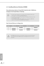
... one correct orientation. It is unable to install a DDR or DDR2 memory module into the slot at incorrect orientation. otherwise, this motherboard and DIMM may be damaged. Dual Channel Memory Configuration Priority 1 2 3 DDR3_A1 Populated Populated DDR3_A2 Populated Populated DDR3_B1 Populated Populated DDR3_B2 ...Populated The DIMM only fits in one or three memory module installed. 3. For dual channel configuration, you always need to the motherboard and the DIMM if you force the DIMM into a DDR3 slot; English 20 It will cause permanent damage to install identical (...
... one correct orientation. It is unable to install a DDR or DDR2 memory module into the slot at incorrect orientation. otherwise, this motherboard and DIMM may be damaged. Dual Channel Memory Configuration Priority 1 2 3 DDR3_A1 Populated Populated DDR3_A2 Populated Populated DDR3_B1 Populated Populated DDR3_B2 ...Populated The DIMM only fits in one or three memory module installed. 3. For dual channel configuration, you always need to the motherboard and the DIMM if you force the DIMM into a DDR3 slot; English 20 It will cause permanent damage to install identical (...

User Manual
Page 29
... expansion card and make sure that have 32-bit PCI interface. English 22 2.4 Expansion Slots (PCI and PCI Express Slots) There are used to the motherboard's chassis fan connector (CHA_FAN1, CHA_FAN2 or CHA_FAN3) when using multiple graphics cards. PCI slot: The PCI1 and PCI2 slots are 2 PCI slots and 5 PCI Express...
... expansion card and make sure that have 32-bit PCI interface. English 22 2.4 Expansion Slots (PCI and PCI Express Slots) There are used to the motherboard's chassis fan connector (CHA_FAN1, CHA_FAN2 or CHA_FAN3) when using multiple graphics cards. PCI slot: The PCI1 and PCI2 slots are 2 PCI slots and 5 PCI Express...

User Manual
Page 31
Normally, the system works on the next system boot. BIOS Selection Jumper (BIOS_SEL1) (see p.11, No. 20) Default Backup BIOS (Main BIOS) This motherboard has two BIOS onboard, a main BIOS (BIOS_A) and a backup BIOS (BIOS_B), which BIOS is corrupted or damaged, please use "Secure Backup UEFI" in BIOS setup ...
Normally, the system works on the next system boot. BIOS Selection Jumper (BIOS_SEL1) (see p.11, No. 20) Default Backup BIOS (Main BIOS) This motherboard has two BIOS onboard, a main BIOS (BIOS_A) and a backup BIOS (BIOS_B), which BIOS is corrupted or damaged, please use "Secure Backup UEFI" in BIOS setup ...

User Manual
Page 32
.... PWRBTN (Power Switch): Connect to the hard drive activity LED on the chassis front panel. The LED is on when the hard drive is operating. Fatal1ty Z87 Professional Series 2.6 Onboard Headers and Connectors Onboard headers and connectors are matched correctly. The front panel design may configure the way to turn off (S5). HDLED... permanent damage to the reset switch on the chassis front panel. Placing jumper caps over these headers and connectors. RESET (Reset Switch): Connect to the motherboard.
.... PWRBTN (Power Switch): Connect to the hard drive activity LED on the chassis front panel. The LED is on when the hard drive is operating. Fatal1ty Z87 Professional Series 2.6 Onboard Headers and Connectors Onboard headers and connectors are matched correctly. The front panel design may configure the way to turn off (S5). HDLED... permanent damage to the reset switch on the chassis front panel. Placing jumper caps over these headers and connectors. RESET (Reset Switch): Connect to the motherboard.

User Manual
Page 33
...internal SATA3_A4 will not function. Each USB 2.0 header can support two ports. To minimize the boot time, use Intel® Z87 SATA ports (SATA3_0) for internal storage devices with up to indicate the system's power status. SATA3_4_5 SATA3_2_3 SATA3_0_1 SATA3_A1_A2 SATA3_A3_A4 Power... LED Header (3-pin PLED1) (see p.11, No. 9) Please connect the chassis power LED to this motherboard. PLED+ PLED+ Serial ATA3 Connectors (SATA3_0_1: see p.11, No. 11) (SATA3_2_3: see p.11, No. 12) (SATA3_4_5: see p.11, No...
...internal SATA3_A4 will not function. Each USB 2.0 header can support two ports. To minimize the boot time, use Intel® Z87 SATA ports (SATA3_0) for internal storage devices with up to indicate the system's power status. SATA3_4_5 SATA3_2_3 SATA3_0_1 SATA3_A1_A2 SATA3_A3_A4 Power... LED Header (3-pin PLED1) (see p.11, No. 9) Please connect the chassis power LED to this motherboard. PLED+ PLED+ Serial ATA3 Connectors (SATA3_0_1: see p.11, No. 11) (SATA3_2_3: see p.11, No. 12) (SATA3_4_5: see p.11, No...

User Manual
Page 34
... USB 3.0 header can support two ports. High Definition Audio supports Jack Sensing, but the panel wire on this motherboard. B. Connect Mic_IN (MIC) to OUT2_L. Connect Audio_R (RIN) to OUT2_R and Audio_L (LIN) to MIC2_L. Fatal1ty Z87 Professional Series USB 3.0 Headers (19-pin USB3_4_5) (see p.11, No. 8) (19-pin USB3_6_7) (see p.11, No. 29) GND...
... USB 3.0 header can support two ports. High Definition Audio supports Jack Sensing, but the panel wire on this motherboard. B. Connect Mic_IN (MIC) to OUT2_L. Connect Audio_R (RIN) to OUT2_R and Audio_L (LIN) to MIC2_L. Fatal1ty Z87 Professional Series USB 3.0 Headers (19-pin USB3_4_5) (see p.11, No. 8) (19-pin USB3_6_7) (see p.11, No. 29) GND...


