

User Manual
Page 4
...sport. he next year I would be a World Champion PC gamer. Competing at Quakecon 2004, I 've been blessed with a new car. Fatal1ty Story Who knew that at age 19, I won the same title playing Unreal Tournament 2003, becoming the only three-time CPL champion of the year... I followed that competition and walked away with great hand-eye coordination and a grasp of against the top 12 players in addition to (-1) killer victory. At QuakeCon 2002, I entered the CPL (Cyberathlete Professional League) tournament in Dallas and won that success by defeating Daler in shaping eSports...
...sport. he next year I would be a World Champion PC gamer. Competing at Quakecon 2004, I 've been blessed with a new car. Fatal1ty Story Who knew that at age 19, I won the same title playing Unreal Tournament 2003, becoming the only three-time CPL champion of the year... I followed that competition and walked away with great hand-eye coordination and a grasp of against the top 12 players in addition to (-1) killer victory. At QuakeCon 2002, I entered the CPL (Cyberathlete Professional League) tournament in Dallas and won that success by defeating Daler in shaping eSports...

User Manual
Page 7
Chapter 3 Software and Utilities Operation 37 3.1 Installing Drivers 37 3.2 F-Stream 38 3.3 Killer Network Manager 44 3.3.1 Installing Killer Network Manager 44 3.3.2 Using Killer Network Manager 44 3.4 ASRock APP Shop 47 3.4.1 UI Overview 47 3.4.2 Apps 48 3.4.3 BIOS & Drivers 51 3.4.4 Setting 52 3.5 Start8 53 3.6 XSplit Broadcaster 56 3.6.1 Live Streaming Your Gameplay 56 3.6.2 Recording Your ...
Chapter 3 Software and Utilities Operation 37 3.1 Installing Drivers 37 3.2 F-Stream 38 3.3 Killer Network Manager 44 3.3.1 Installing Killer Network Manager 44 3.3.2 Using Killer Network Manager 44 3.4 ASRock APP Shop 47 3.4.1 UI Overview 47 3.4.2 Apps 48 3.4.3 BIOS & Drivers 51 3.4.4 Setting 52 3.5 Start8 53 3.6 XSplit Broadcaster 56 3.6.1 Live Streaming Your Gameplay 56 3.6.2 Recording Your ...
User Manual
Page 9
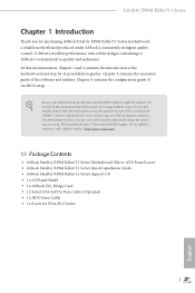
... to quality and endurance. ASRock website http://www.asrock.com. 1.1 Package Contents • ASRock Fatal1ty X99M Killer/3.1 Series Motherboard (Micro ATX Form Factor) • ASRock Fatal1ty X99M Killer/3.1 Series Quick Installation Guide • ASRock Fatal1ty X99M Killer/3.1 Series Support CD • 1 x I/O Panel Shield • 1 x ASRock SLI_Bridge Card • 2 x Serial ATA (SATA) Data Cables (Optional) • 1 x HDD Saver Cable • 1 x Screw for purchasing ASRock Fatal1ty X99M Killer/3.1 Series motherboard, a reliable...
... to quality and endurance. ASRock website http://www.asrock.com. 1.1 Package Contents • ASRock Fatal1ty X99M Killer/3.1 Series Motherboard (Micro ATX Form Factor) • ASRock Fatal1ty X99M Killer/3.1 Series Quick Installation Guide • ASRock Fatal1ty X99M Killer/3.1 Series Support CD • 1 x I/O Panel Shield • 1 x ASRock SLI_Bridge Card • 2 x Serial ATA (SATA) Data Cables (Optional) • 1 x HDD Saver Cable • 1 x Screw for purchasing ASRock Fatal1ty X99M Killer/3.1 Series motherboard, a reliable...

User Manual
Page 11
Direct Drive Technology - Fatal1ty X99M Killer/3.1 Series LAN Rear Panel I/O • Supports Surge Protection (ASRock Full Spike Protection) • Supports Purity SoundTM 2 - EMI Shielding Cover - TI® NE5532 Premium ...1 x eSATA Connector • 3 x USB 2.0 Ports (Supports ESD Protection (ASRock Full Spike Protection)) • 1 x Fatal1ty Mouse Port (USB 2.0) (Supports ESD Protection (ASRock Full Spike Protection)) • 2 x USB 3.1 Type-A Ports (10 Gb/s) (ASMedia ASM1142) (Supports ESD Protection (ASRock Full Spike Protection)) • 2 x USB 3.0 Ports (Intel® X99) ...
Direct Drive Technology - Fatal1ty X99M Killer/3.1 Series LAN Rear Panel I/O • Supports Surge Protection (ASRock Full Spike Protection) • Supports Purity SoundTM 2 - EMI Shielding Cover - TI® NE5532 Premium ...1 x eSATA Connector • 3 x USB 2.0 Ports (Supports ESD Protection (ASRock Full Spike Protection)) • 1 x Fatal1ty Mouse Port (USB 2.0) (Supports ESD Protection (ASRock Full Spike Protection)) • 2 x USB 3.1 Type-A Ports (10 Gb/s) (ASMedia ASM1142) (Supports ESD Protection (ASRock Full Spike Protection)) • 2 x USB 3.0 Ports (Intel® X99) ...

User Manual
Page 13
... not responsible for system usage under Windows® 32-bit operating systems. Windows® 64-bit operating systems do not have such limitations. English 5 Fatal1ty X99M Killer/3.1 Series Hardware Monitor OS Certiications • SMBIOS 2.3.1 Support • CPU, DRAM, PCH 1.05V, PCH 1.5V, VPPM Voltage Multi- adjustment •...; ErP/EuP Ready (ErP/EuP ready power supply is required) * For detailed product information, please visit our website: http://www.asrock.com Please realize that Windows® cannot use ASRock XFast RAM to the components and devices of your system.
... not responsible for system usage under Windows® 32-bit operating systems. Windows® 64-bit operating systems do not have such limitations. English 5 Fatal1ty X99M Killer/3.1 Series Hardware Monitor OS Certiications • SMBIOS 2.3.1 Support • CPU, DRAM, PCH 1.05V, PCH 1.5V, VPPM Voltage Multi- adjustment •...; ErP/EuP Ready (ErP/EuP ready power supply is required) * For detailed product information, please visit our website: http://www.asrock.com Please realize that Windows® cannot use ASRock XFast RAM to the components and devices of your system.

User Manual
Page 14
...Central/Bass LINE IN Center: REAR SPK Bottom: Optical SPDIF Super I/O 9 S_SATA3_0_1 Top: Center: FRONT Bottom: MIC IN 31 Killer E2200 PWR_FAN1 CMOS Battery BIOS_A_LED A 128Mb BIOS BIOS_A 128Mb BIOS BIOS_B BIOS_B_LED B BIOS_SEL1 CHA_FAN2 10 11 S_SATA3_2_3 PCIE1 SATA3_0_3 30 RoHS ... M.2 PCIe Gen3 x4 12 M2_1 CT5 Purity SoundTM 2 CT4 CT3 CT2 CT1 1 FATAL TY PCIE2 Intel SATA3_1_4 X99 13 14 SATA3_2_5 X99M KILLER/3.1 SATAE_1 HD_AUDIO1 1 PCIE_PWR1 PCIE3 TBT1 COM1 1 1 USB5_6 USB7_8 1 1 CHA_FAN1 SPEAKER1 1 CLRMOS1 1 Reset Power PANEL1 PLED PWRBTN 1...
...Central/Bass LINE IN Center: REAR SPK Bottom: Optical SPDIF Super I/O 9 S_SATA3_0_1 Top: Center: FRONT Bottom: MIC IN 31 Killer E2200 PWR_FAN1 CMOS Battery BIOS_A_LED A 128Mb BIOS BIOS_A 128Mb BIOS BIOS_B BIOS_B_LED B BIOS_SEL1 CHA_FAN2 10 11 S_SATA3_2_3 PCIE1 SATA3_0_3 30 RoHS ... M.2 PCIe Gen3 x4 12 M2_1 CT5 Purity SoundTM 2 CT4 CT3 CT2 CT1 1 FATAL TY PCIE2 Intel SATA3_1_4 X99 13 14 SATA3_2_5 X99M KILLER/3.1 SATAE_1 HD_AUDIO1 1 PCIE_PWR1 PCIE3 TBT1 COM1 1 1 USB5_6 USB7_8 1 1 CHA_FAN1 SPEAKER1 1 CLRMOS1 1 Reset Power PANEL1 PLED PWRBTN 1...
User Manual
Page 15
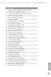
... AIC Connector (TBT1) 28 PCIe Power Connector (PCIE_PWR1) 29 Front Panel Audio Header (HD_AUDIO1) 30 BIOS Selection Switch (BIOS_SEL1) 31 Power Fan Connector (PWR_FAN1) 7 English Fatal1ty X99M Killer/3.1 Series No.
... AIC Connector (TBT1) 28 PCIe Power Connector (PCIE_PWR1) 29 Front Panel Audio Header (HD_AUDIO1) 30 BIOS Selection Switch (BIOS_SEL1) 31 Power Fan Connector (PWR_FAN1) 7 English Fatal1ty X99M Killer/3.1 Series No.

User Manual
Page 17
... on each LAN port. Audio Output Channels 2 4 6 8 Front Speaker (No. 8) V V V V Rear Speaker (No. 6) -V V V Central / Bass (No. 5) --V V Line In (No. 7) ---V To enable Multi-Streaming, you use. Fatal1ty X99M Killer/3.1 Series * here are allowed to select "Realtek HDA Primary output" to use the Rear Speaker, Central/Bass, and Front Speaker, or select "Realtek HDA Audio...
... on each LAN port. Audio Output Channels 2 4 6 8 Front Speaker (No. 8) V V V V Rear Speaker (No. 6) -V V V Central / Bass (No. 5) --V V Line In (No. 7) ---V To enable Multi-Streaming, you use. Fatal1ty X99M Killer/3.1 Series * here are allowed to select "Realtek HDA Primary output" to use the Rear Speaker, Central/Bass, and Front Speaker, or select "Realtek HDA Audio...

User Manual
Page 19
..., or if there are any bent pins in the socket. Unplug all power cables before installing the CPU. Otherwise, the CPU will be seriously damaged. 2. Fatal1ty X99M Killer/3.1 Series 2.1 Installing the CPU 1. CAUTION: Please note that X99 platform is only compatible with the LGA 2011-3 socket, which is found. Before you insert the...
..., or if there are any bent pins in the socket. Unplug all power cables before installing the CPU. Otherwise, the CPU will be seriously damaged. 2. Fatal1ty X99M Killer/3.1 Series 2.1 Installing the CPU 1. CAUTION: Please note that X99 platform is only compatible with the LGA 2011-3 socket, which is found. Before you insert the...

User Manual
Page 21
he cover must be placed if you wish to return the motherboard for ater service. 13 6 7 A B 8 Fatal1ty X99M Killer/3.1 Series A B English Please save and replace the cover if the processor is removed.
he cover must be placed if you wish to return the motherboard for ater service. 13 6 7 A B 8 Fatal1ty X99M Killer/3.1 Series A B English Please save and replace the cover if the processor is removed.

User Manual
Page 23
... two memory modules are installed in one correct orientation. he DIMM only its in the DDR4 DIMM slots, then Dual Channel Memory Technology is activated. Fatal1ty X99M Killer/3.1 Series 2.3 Installation of Memory Modules (DIMM) his motherboard provides four 288-pin DDR4 (Double Data Rate 4) DIMM slots, and supports Quad Channel Memory Technology. 1. It...
... two memory modules are installed in one correct orientation. he DIMM only its in the DDR4 DIMM slots, then Dual Channel Memory Technology is activated. Fatal1ty X99M Killer/3.1 Series 2.3 Installation of Memory Modules (DIMM) his motherboard provides four 288-pin DDR4 (Double Data Rate 4) DIMM slots, and supports Quad Channel Memory Technology. 1. It...

User Manual
Page 25
... fan connector (CHA_FAN1 or CHA_FAN2) when using multiple graphics cards. PCIE2 (PCIe 3.0 x16 slot) is used for PCI Express x4 lane width cards. English 17 Fatal1ty X99M Killer/3.1 Series 2.4 Expansion Slots (PCI Express Slots) here are 3 PCI Express slots on the motherboard.
... fan connector (CHA_FAN1 or CHA_FAN2) when using multiple graphics cards. PCIE2 (PCIe 3.0 x16 slot) is used for PCI Express x4 lane width cards. English 17 Fatal1ty X99M Killer/3.1 Series 2.4 Expansion Slots (PCI Express Slots) here are 3 PCI Express slots on the motherboard.

User Manual
Page 27
... the hard drive is operating. Placing jumper caps over these headers and connectors. he LED is on when the system is reading or writing data. Fatal1ty X99M Killer/3.1 Series 2.6 Onboard Headers and Connectors Onboard headers and connectors are matched correctly.
... the hard drive is operating. Placing jumper caps over these headers and connectors. he LED is on when the system is reading or writing data. Fatal1ty X99M Killer/3.1 Series 2.6 Onboard Headers and Connectors Onboard headers and connectors are matched correctly.

User Manual
Page 29
... the front mic, go to the front panel audio header by the steps below: A. Connect Audio_R (RIN) to OUT2_R and Audio_L (LIN) to this motherboard. Fatal1ty X99M Killer/3.1 Series USB 2.0 Headers (9-pin USB5_6) (see p.6, No. 25) (9-pin USB7_8) (see p.6, No. 24) USB_PWR PP+ GND DUMMY 1 GND P+ PUSB_PWR Besides four USB 2.0 ports on the...
... the front mic, go to the front panel audio header by the steps below: A. Connect Audio_R (RIN) to OUT2_R and Audio_L (LIN) to this motherboard. Fatal1ty X99M Killer/3.1 Series USB 2.0 Headers (9-pin USB5_6) (see p.6, No. 25) (9-pin USB7_8) (see p.6, No. 24) USB_PWR PP+ GND DUMMY 1 GND P+ PUSB_PWR Besides four USB 2.0 ports on the...

User Manual
Page 31
... connector when more than three graphics cards are installed. A TPM system also helps enhance network security, protects digital identities, and ensures platform integrity. English 23 Fatal1ty X99M Killer/3.1 Series PCIe Power Connector (4-pin PCIE_PWR1) (see p.6, No. 28) HDD Saver Connector (4-pin SATA_PWR_1) (see p.6, No. 16) hunderbolt AIC Connector (5-pin TBT1) (see p.6, No. 27...
... connector when more than three graphics cards are installed. A TPM system also helps enhance network security, protects digital identities, and ensures platform integrity. English 23 Fatal1ty X99M Killer/3.1 Series PCIe Power Connector (4-pin PCIE_PWR1) (see p.6, No. 28) HDD Saver Connector (4-pin SATA_PWR_1) (see p.6, No. 16) hunderbolt AIC Connector (5-pin TBT1) (see p.6, No. 27...

User Manual
Page 33
Please re-install the memory and CPU. A0 - Fatal1ty X99M Killer/3.1 Series 2.8 Dr. Debug Dr. Debug is installed correctly and then clear CMOS. 0d Problem related to memory, VGA card or other devices. Please see the ...
Please re-install the memory and CPU. A0 - Fatal1ty X99M Killer/3.1 Series 2.8 Dr. Debug Dr. Debug is installed correctly and then clear CMOS. 0d Problem related to memory, VGA card or other devices. Please see the ...

User Manual
Page 35
... to the PCI Express graphics cards. 27 English You should only use a NVIDIA® certiied PSU. Make sure that are properly seated on the slots. Fatal1ty X99M Killer/3.1 Series 2.9 SLITM and Quad SLITM Operation Guide his motherboard supports NVIDIA® SLITM and Quad SLITM (Scalable Link Interface) technology that the cards are NVIDIA...
... to the PCI Express graphics cards. 27 English You should only use a NVIDIA® certiied PSU. Make sure that are properly seated on the slots. Fatal1ty X99M Killer/3.1 Series 2.9 SLITM and Quad SLITM Operation Guide his motherboard supports NVIDIA® SLITM and Quad SLITM (Scalable Link Interface) technology that the cards are NVIDIA...

User Manual
Page 37
Step 1 Double-click the NVIDIA Control Panel icon in the NVIDIA® nView system tray utility. Please follow the below procedures to your system. 29 English Step 2 In the let pane, click Set SLI and PhysX coniguration. hen select Maximize 3D performance and click Apply. Fatal1ty X99M Killer/3.1 Series 2.9.2 Driver Installation and Setup Install the graphics card drivers to enable the multi-GPU. Ater that, you can enable the Multi-Graphics Processing Unit (GPU) in the Windows® system tray. Step 3 Reboot your system.
Step 1 Double-click the NVIDIA Control Panel icon in the NVIDIA® nView system tray utility. Please follow the below procedures to your system. 29 English Step 2 In the let pane, click Set SLI and PhysX coniguration. hen select Maximize 3D performance and click Apply. Fatal1ty X99M Killer/3.1 Series 2.9.2 Driver Installation and Setup Install the graphics card drivers to enable the multi-GPU. Ater that, you can enable the Multi-Graphics Processing Unit (GPU) in the Windows® system tray. Step 3 Reboot your system.

User Manual
Page 39
Fatal1ty X99M Killer/3.1 Series Step 3 Connect a VGA cable or a DVI cable to the monitor connector or the DVI connector of the graphics card that is inserted to PCIE1 slot. 31 English
Fatal1ty X99M Killer/3.1 Series Step 3 Connect a VGA cable or a DVI cable to the monitor connector or the DVI connector of the graphics card that is inserted to PCIE1 slot. 31 English

User Manual
Page 41
... length of your M.2_SSD (NGFF) module, ind the corresponding nut location to be noted that aims to replace mPCIe and mSATA. Please be used. E D C B A No. Fatal1ty X99M Killer/3.1 Series 2.11 M.2_SSD (NGFF) Module Installation Guide he Ultra M.2 Socket (M2_1) can only choose either a M.2 SATA3 6.0 Gb/s module or a M.2 PCI Express module up to Gen3...
... length of your M.2_SSD (NGFF) module, ind the corresponding nut location to be noted that aims to replace mPCIe and mSATA. Please be used. E D C B A No. Fatal1ty X99M Killer/3.1 Series 2.11 M.2_SSD (NGFF) Module Installation Guide he Ultra M.2 Socket (M2_1) can only choose either a M.2 SATA3 6.0 Gb/s module or a M.2 PCI Express module up to Gen3...