
User Manual
Page 2
...fications and information contained in this motherboard contains Perchlorate, a toxic substance controlled in Perchlorate Best Management Practices (BMP) regulations passed by the California Legislature. This device complies with Part 15 of documentation by ASRock. When you discard the Lithium battery in... following two conditions: (1) this device may cause undesired operation. Copyright Notice: No part of this manual. ASRock assumes no event shall ASRock, its directors, of this device must accept any interference received, including interference that may appear in this manual...
...fications and information contained in this motherboard contains Perchlorate, a toxic substance controlled in Perchlorate Best Management Practices (BMP) regulations passed by the California Legislature. This device complies with Part 15 of documentation by ASRock. When you discard the Lithium battery in... following two conditions: (1) this device may cause undesired operation. Copyright Notice: No part of this manual. ASRock assumes no event shall ASRock, its directors, of this device must accept any interference received, including interference that may appear in this manual...

User Manual
Page 3
Contents 1 Introduction 5 1.1 Package Contents 5 1.2 Specifications 6 1.3 Motherboard Layout 10 1.4 I/O Panel 11 2 Installation 13 2.1 Screw Holes 13 2.2 Pre-installation Precautions 13 2.3 Installation of Memory Modules (DIMM 14 2.4 Expansion Slot (PCI Express Slot 15 2.5 ...
Contents 1 Introduction 5 1.1 Package Contents 5 1.2 Specifications 6 1.3 Motherboard Layout 10 1.4 I/O Panel 11 2 Installation 13 2.1 Screw Holes 13 2.2 Pre-installation Precautions 13 2.3 Installation of Memory Modules (DIMM 14 2.4 Expansion Slot (PCI Express Slot 15 2.5 ...
User Manual
Page 5
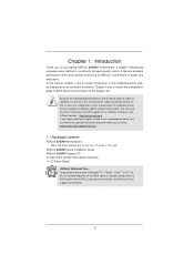
... you for specific information about the model you require technical support related to this motherboard, please visit our website for purchasing ASRock E350M1 motherboard, a reliable motherboard produced under ASRock's consistently stringent quality control. It delivers excellent performance with robust design conforming to ASRock's commitment to the "User Manual" in our support CD for details. 5 Because the...
... you for specific information about the model you require technical support related to this motherboard, please visit our website for purchasing ASRock E350M1 motherboard, a reliable motherboard produced under ASRock's consistently stringent quality control. It delivers excellent performance with robust design conforming to ASRock's commitment to the "User Manual" in our support CD for details. 5 Because the...

User Manual
Page 8
.../EuP Ready (ErP/EuP ready power supply is no longer only available at your motherboard, and also download the free AIWI Lite from ASRock official website or ASRock software support CD to your own risk and expense. It should be noted that ... using the third-party overclocking tools. OS - For audio output, this motherboard supports both stereo and mono modes. Please be done at Wii. Connecting 8 For microphone input, this motherboard supports 2-channel, 4-channel, 6-channel, and 8-channel modes. ASRock Instant Flash is no such limitation. 2. Microsoft® Windows® ...
.../EuP Ready (ErP/EuP ready power supply is no longer only available at your motherboard, and also download the free AIWI Lite from ASRock official website or ASRock software support CD to your own risk and expense. It should be noted that ... using the third-party overclocking tools. OS - For audio output, this motherboard supports both stereo and mono modes. Please be done at Wii. Connecting 8 For microphone input, this motherboard supports 2-channel, 4-channel, 6-channel, and 8-channel modes. ASRock Instant Flash is no such limitation. 2. Microsoft® Windows® ...

User Manual
Page 9
... even supports continuous charging when your PC enters into an enhanced view for more personal Internet experience. The performance may depend on the motherboard functions properly and unplug the power cord, then plug it makes your iPhone charged much quickly from your real-time newsfeed into Standby ...install the PC system. 9. If you desire a faster, less restricted way of the completed system shall be under 100 mA current consumption. ASRock motherboards are required. Simply installing the APP Charger driver, it back again. your Apple devices, such as iPhone/iPod/iPad Touch...
... even supports continuous charging when your PC enters into an enhanced view for more personal Internet experience. The performance may depend on the motherboard functions properly and unplug the power cord, then plug it makes your iPhone charged much quickly from your real-time newsfeed into Standby ...install the PC system. 9. If you desire a faster, less restricted way of the completed system shall be under 100 mA current consumption. ASRock motherboards are required. Simply installing the APP Charger driver, it back again. your Apple devices, such as iPhone/iPod/iPad Touch...
User Manual
Page 10
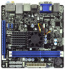
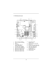
1.3 Motherboard Layout USB 2.0 T: USB0 B: USB1 12 34 17.0cm (6.7 in) E350M1 CHA_FAN1 5 DDR3 CMOS Battery PS2 Keyboard/Mouse 6 CLRCMOS1 1 17.0cm (6.7 in) SATA3 6Gb/s DDR3_A1 (64 bit, 240-FpinSBmo8d0ul0e) DDR3_A2 (64 bit, 240-FpinSBmo8d0ul0e) CPU_FAN1 DVI_CON1 ...
1.3 Motherboard Layout USB 2.0 T: USB0 B: USB1 12 34 17.0cm (6.7 in) E350M1 CHA_FAN1 5 DDR3 CMOS Battery PS2 Keyboard/Mouse 6 CLRCMOS1 1 17.0cm (6.7 in) SATA3 6Gb/s DDR3_A1 (64 bit, 240-FpinSBmo8d0ul0e) DDR3_A2 (64 bit, 240-FpinSBmo8d0ul0e) CPU_FAN1 DVI_CON1 ...

User Manual
Page 13
...;ts into the holes indicated by the edges and do so may cause physical injuries to you and damages to motherboard components. 2.1 Screw Holes Place screws into it. Make sure to use a grounded wrist strap or touch a safety grounded object before touching any component, ...ensure that the power is switched off or the power cord is a Mini-ITX form factor (6.7" x 6.7", 17.0 x 17.0 cm) motherboard. Doing so may cause severe damage to the chassis. Chapter 2: Installation This is detached from the wall socket before you handle components. 3.
...;ts into the holes indicated by the edges and do so may cause physical injuries to you and damages to motherboard components. 2.1 Screw Holes Place screws into it. Make sure to use a grounded wrist strap or touch a safety grounded object before touching any component, ...ensure that the power is switched off or the power cord is a Mini-ITX form factor (6.7" x 6.7", 17.0 x 17.0 cm) motherboard. Doing so may cause severe damage to the chassis. Chapter 2: Installation This is detached from the wall socket before you handle components. 3.
User Manual
Page 14
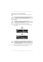
... DIMM on the slot such that the notch on the DIMM matches the break on the slot. It will cause permanent damage to the motherboard and the DIMM if you force the DIMM into the slot until the retaining clips at incorrect orientation. Step 1. It is properly seated.... 14 Unlock a DIMM slot by pressing the retaining clips outward. otherwise, this motherboard and DIMM may be damaged. 2.3 Installation of Memory Modules (DIMM) E350M1 motherboard provides two 240-pin DDR3 (Double Data Rate 3) DIMM slots. Step 3.
... DIMM on the slot such that the notch on the DIMM matches the break on the slot. It will cause permanent damage to the motherboard and the DIMM if you force the DIMM into the slot until the retaining clips at incorrect orientation. Step 1. It is properly seated.... 14 Unlock a DIMM slot by pressing the retaining clips outward. otherwise, this motherboard and DIMM may be damaged. 2.3 Installation of Memory Modules (DIMM) E350M1 motherboard provides two 240-pin DDR3 (Double Data Rate 3) DIMM slots. Step 3.

User Manual
Page 15
...Express x4 lane width graphics cards. Align the card connector with screws. Replace the system cover. 15 Blue) is completely seated on this motherboard. Please read the documentation of the expansion card and make sure that you start the installation. Step 5. Remove the system unit cover (if... your motherboard is unplugged. Fasten the card to use . Step 2. Remove the bracket facing the slot that the power supply is switched off or...
...Express x4 lane width graphics cards. Align the card connector with screws. Replace the system cover. 15 Blue) is completely seated on this motherboard. Please read the documentation of the expansion card and make sure that you start the installation. Step 5. Remove the system unit cover (if... your motherboard is unplugged. Fasten the card to use . Step 2. Remove the bracket facing the slot that the power supply is switched off or...
User Manual
Page 16
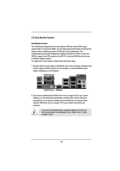
... feature, please follow the below steps: 1. If you have installed onboard VGA driver from our support CD to this motherboard. 2.5 Dual Monitor Feature Dual Monitor Feature This motherboard supports dual monitor feature. VGA/D-Sub port VGA/DVI-D port HDMI port 2. You can easily enjoy the benefi...ts of dual monitor function after your computer. D-Sub, DVI-D and HDMI monitors cannot be enabled at the same time. This motherboard also provides independent display controllers for DVI-D, D-Sub and HDMI to HDMI port on VGA card to your system and restart your system boots....
... feature, please follow the below steps: 1. If you have installed onboard VGA driver from our support CD to this motherboard. 2.5 Dual Monitor Feature Dual Monitor Feature This motherboard supports dual monitor feature. VGA/D-Sub port VGA/DVI-D port HDMI port 2. You can easily enjoy the benefi...ts of dual monitor function after your computer. D-Sub, DVI-D and HDMI monitors cannot be enabled at the same time. This motherboard also provides independent display controllers for DVI-D, D-Sub and HDMI to HDMI port on VGA card to your system and restart your system boots....

User Manual
Page 17
... words, HDCP specification is designed to eliminate the possibility of content as it is HDCP? HDCP Function HDCP function is supported on this motherboard, you can enjoy the superior display quality with the HDCP scheme such as DVD players, satellite and cable HDTV set -top box and the digital... or projector. Therefore, you need to the increase in manufacturers employing HDCP in their equipment, it is being transmitted. To use HDCP function with this motherboard.
... words, HDCP specification is designed to eliminate the possibility of content as it is HDCP? HDCP Function HDCP function is supported on this motherboard, you can enjoy the superior display quality with the HDCP scheme such as DVD players, satellite and cable HDTV set -top box and the digital... or projector. Therefore, you need to the increase in manufacturers employing HDCP in their equipment, it is being transmitted. To use HDCP function with this motherboard.

User Manual
Page 19
...interface for internal storage devices. The current SATA3 interface allows up to the SATA / SATAII / SATA3 hard disk or the SATAII / SATA3 connector on this motherboard. Placing jumper caps over these headers and connectors. Serial ATA3 Connectors (SATA3_1: see p.10, No. 12) (SATA3_2: see p.10, No. 10)...convenient connection and control of audio devices. SATA3_1 SATA3_2 SATA3_3 SATA3_4 Serial ATA (SATA) Data Cable (Optional) Either end of the motherboard! Do NOT place jumper caps over the headers and connectors will cause permanent damage of the SATA data cable can be used to...
...interface for internal storage devices. The current SATA3 interface allows up to the SATA / SATAII / SATA3 hard disk or the SATAII / SATA3 connector on this motherboard. Placing jumper caps over these headers and connectors. Serial ATA3 Connectors (SATA3_1: see p.10, No. 12) (SATA3_2: see p.10, No. 10)...convenient connection and control of audio devices. SATA3_1 SATA3_2 SATA3_3 SATA3_4 Serial ATA (SATA) Data Cable (Optional) Either end of the motherboard! Do NOT place jumper caps over the headers and connectors will cause permanent damage of the SATA data cable can be used to...

User Manual
Page 21
... and match the black wire to the ground pin. Serial port Header (9-pin COM1) (see p.10 No. 13) Please connect the chassis speaker to this motherboard provides 24-pin ATX power connector, 12 24 it can still work if you adopt a traditional 20-pin ATX power supply. When connecting your power...
... and match the black wire to the ground pin. Serial port Header (9-pin COM1) (see p.10 No. 13) Please connect the chassis speaker to this motherboard provides 24-pin ATX power connector, 12 24 it can still work if you adopt a traditional 20-pin ATX power supply. When connecting your power...

User Manual
Page 22
2.8 Serial ATA3 (SATA3) Hard Disks Installation This motherboard adopts AMD A50M chipset that supports Serial ATA3 (SATA3) hard disks. STEP 2: Connect the SATA power cable to the motherboard's SATA3 connector. STEP 1: Install the SATA3 hard disks into the drive bays of the SATA data cable to install the SATA3 hard disks. STEP 4: Connect the other end of your chassis. You may install SATA3 hard disks on this motherboard for internal storage devices. STEP 3: Connect one end of the SATA data cable to the SATA3 hard disk. This section will guide you to the SATA3 hard disk. 22
2.8 Serial ATA3 (SATA3) Hard Disks Installation This motherboard adopts AMD A50M chipset that supports Serial ATA3 (SATA3) hard disks. STEP 2: Connect the SATA power cable to the motherboard's SATA3 connector. STEP 1: Install the SATA3 hard disks into the drive bays of the SATA data cable to install the SATA3 hard disks. STEP 4: Connect the other end of your chassis. You may install SATA3 hard disks on this motherboard for internal storage devices. STEP 3: Connect one end of the SATA data cable to the SATA3 hard disk. This section will guide you to the SATA3 hard disk. 22

User Manual
Page 23
... Hot Plug Function? NOTE What is called "Hot Plug" for SATA host controllers developed thru a joint industry effort. 2.9 Hot Plug Function for SATA3 HDDs This motherboard supports Hot Plug function for SATA3 in working condition.
... Hot Plug Function? NOTE What is called "Hot Plug" for SATA host controllers developed thru a joint industry effort. 2.9 Hot Plug Function for SATA3 HDDs This motherboard supports Hot Plug function for SATA3 in working condition.

User Manual
Page 24
...sure the SATA / SATAII / SATA3 driver is available on our website: www.asrock.com 2. The latest SATA / SATAII / SATA3 driver is installed into system properly. The SATA / SATAII / SATA3 HDD, which are from our motherboard package. 5. Before you process the Hot Plug: 1. SATA power cable with...pin SATA data cable B. Make sure to power supply 1. Make sure your SATA / SATAII / SATA3 HDD can support Hot Plug function from the motherboard gift box pack. SATA data cable (Red) B. SATA power cable SATA 7-pin connector Caution The SATA 15-pin power connector (Black) connect ...
...sure the SATA / SATAII / SATA3 driver is available on our website: www.asrock.com 2. The latest SATA / SATAII / SATA3 driver is installed into system properly. The SATA / SATAII / SATA3 HDD, which are from our motherboard package. 5. Before you process the Hot Plug: 1. SATA power cable with...pin SATA data cable B. Make sure to power supply 1. Make sure your SATA / SATAII / SATA3 HDD can support Hot Plug function from the motherboard gift box pack. SATA data cable (Red) B. SATA power cable SATA 7-pin connector Caution The SATA 15-pin power connector (Black) connect ...

User Manual
Page 25
the motherboard's SATAII / SATA3 connector. Step 1 Unplug SATA data cable from SATA / SATAII / SATA3 HDD side. 25 How to Hot Plug a SATA / SATAII / SATA3 HDD: Points of ...
the motherboard's SATAII / SATA3 connector. Step 1 Unplug SATA data cable from SATA / SATAII / SATA3 HDD side. 25 How to Hot Plug a SATA / SATAII / SATA3 HDD: Points of ...

User Manual
Page 28
... with the following UEFI setup screens and descriptions are for reference purpose only, and they may also restart by pressing the reset button on the motherboard stores the UEFI SETUP UTILITY. Please press or during the Power-On-Self-Test (POST) to configure your system.
... with the following UEFI setup screens and descriptions are for reference purpose only, and they may also restart by pressing the reset button on the motherboard stores the UEFI SETUP UTILITY. Please press or during the Power-On-Self-Test (POST) to configure your system.

User Manual
Page 30
... setting. Row Precharge Time (tRP) Use this item to change Command Rate (CR) Auto/Manual setting. The default is [Auto]. The default is selected, the motherboard will detect the memory module(s) inserted and assigns appropriate frequency automatically. DRAM Timing Control DRAM Frequency If [Auto] is [Auto]. 30 The default is [Auto...
... setting. Row Precharge Time (tRP) Use this item to change Command Rate (CR) Auto/Manual setting. The default is [Auto]. The default is selected, the motherboard will detect the memory module(s) inserted and assigns appropriate frequency automatically. DRAM Timing Control DRAM Frequency If [Auto] is [Auto]. 30 The default is [Auto...

User Manual
Page 35
... on AC/Power Loss This allows you to enable or disable the "Onboard LAN" feature. If [Power Off] is [Enabled]. ACPI HPET Table Use this motherboard to submit Windows® VistaTM certification. 35 Please set the power state after an unexpected AC/power loss. Front Panel Select [Auto] or...
... on AC/Power Loss This allows you to enable or disable the "Onboard LAN" feature. If [Power Off] is [Enabled]. ACPI HPET Table Use this motherboard to submit Windows® VistaTM certification. 35 Please set the power state after an unexpected AC/power loss. Front Panel Select [Auto] or...


